final project: launching mechanism
November 5, 2020
This week’s topic was output devices, additionally, we don’t have class on Wednesday due to Veterans day. This gave me the opportunity to really spend time working on my final project. As I noted in my last entry, I was going to create my launching mechanism for the output devices week.
solenoid
I had multiple possible ways to create my treat launching mechanism. Professor Gershenfeld recommended that I used a
simple solenoid to launch my treat. I wasn’t familiar with solenoids and was curious if I would get
enough power after watching this video. However, I thought it would be worth a try to experiment with a solenoid.
A solenoid is a coil wound into a tightly packed helix. This coil creates a magnetic field when an electric current passes through it and can cause a magnetic object to shoot forward when activated. Instead of having solenoids lying around, Anthony and I just made our own solenoid. We did so by using magnet wire and coiling the wire around a small spool with an electric screwdriver. We held the magnet wire with this mechanism that would hold the original spool of magnet wire in place.
A solenoid is a coil wound into a tightly packed helix. This coil creates a magnetic field when an electric current passes through it and can cause a magnetic object to shoot forward when activated. Instead of having solenoids lying around, Anthony and I just made our own solenoid. We did so by using magnet wire and coiling the wire around a small spool with an electric screwdriver. We held the magnet wire with this mechanism that would hold the original spool of magnet wire in place.
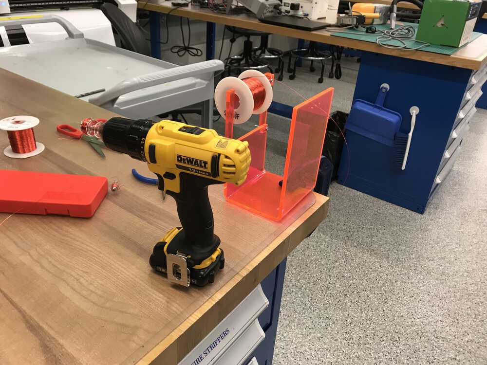
Set up used to create the solenoid
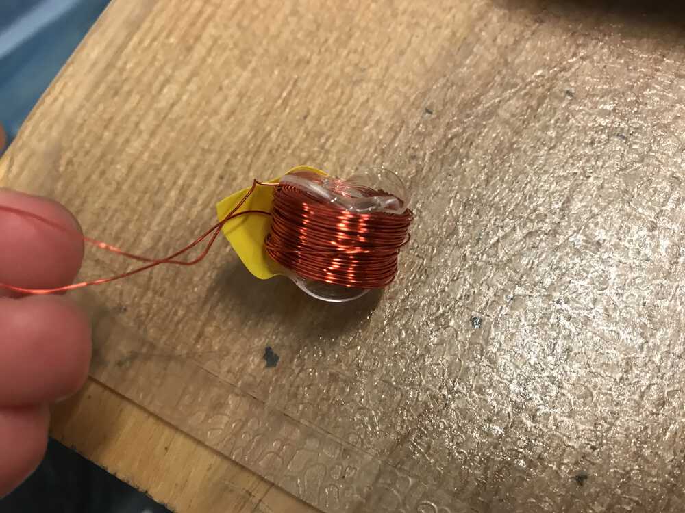
After coiling the magnet wire around the spool multiple times, I learned that I could get a stronger magnetic field by using stronger magnet wire. However, this comes at the cost of fewer coils since the stronger magnet wire is larger. This is something I plan on experimenting with if I end up going down the solenoid route. Nonetheless, with my solenoid made, I stripped the end of the two wires so that we could connect it to the digital bench.
Finished homemade solenoid
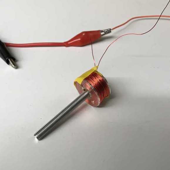
With all things set up, I set the voltage to 10 V and saw that 2.8 A of current was flowing through our solenoid. This is great because I knew things were working. I then unplugged one of the jumper cables and placed a screw through the middle of the solenoid. This should work since the screw was magnetic. Once I plugged the jumper cable back into the digital bench, the screw shot up! It was only a slight jump but it was a noticeable amount.
Screw jumping when passing current through the solenoid
The current velocity that my solenoid provided wasn’t enough for my treat launcher. I suspected that this particular solenoid that I made with this screw would launch my treat a couple of inches. To experiment with another idea, I added two small magnets on the top of the screw and tried again. This caused my screw to go flying!
Screw with magnet jumping when passing current through the solenoid
After this experiment, it became clear that I could potentially use a solenoid. I could use some sort of metal tube that would do the same thing my screw did in my experiment. Additionally, I would need to put someone on the end of the metal tube so that it would stay in between the solenoid. One pro of the solenoid approach is that it is very easy to work with and provides lots of flexibility. However, compared to the stepper motor, there is much less precision.
An aside is that I learned that the solenoid produces a lot of heat when powered on for too long. After these experiments, I learned that the hard way: the plastic spool of magnet wire of my solenoid started to melt and warped once I unplugged it to the digital bench.
An aside is that I learned that the solenoid produces a lot of heat when powered on for too long. After these experiments, I learned that the hard way: the plastic spool of magnet wire of my solenoid started to melt and warped once I unplugged it to the digital bench.
Warped plastic due to the solenoid overheating
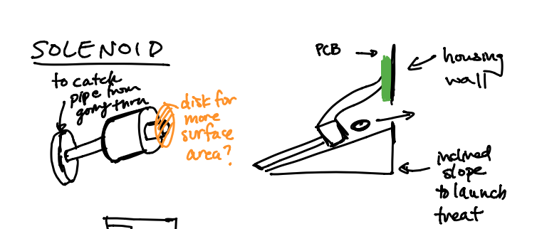
Sketches of solenoid in my device
stepper motor
The other opinion that I can use for my launching mechanism is a stepper motor. The stepper motion is a
brushless DC electric motor that provides full rotation into a number of equal steps.
This is nice because it requires no position sensor for feedback and we can be much more precise with our
motor.
The idea of integrating the stepper motor is promising and I had two possible ways of using it. The first was an idea I stumbled upon on youtube. This was interesting and I thought this was a feasible idea to launch my treats. However, I was concerned about how I would attach the piece that loads the slingshot to my belt. After speaking with Anthony, it looks like that component is fed through the belt. For a belt I would use, it would be very thin and this piece would run into the pulleys causing our belt to not move smoothly. I considered glue gunning this piece to the top of the belt, however, this wouldn’t work because there were no guarantees that this piece would stay glued on with all the force it was experiencing when loading the slingshot.
I then started to focus on my other idea with the rack and pinion. Like I discussed earlier, I had an idea to use a stepper motor to spin a gear that would pull a rack backward. This would ultimately be the loading mechanism for my slingshot. I would then add a smooth side to the gear and this would allow my slingshot to release. This is a very doable idea, but I would have to experiment with different gears and racks. Anthony suggested that I try laser cutting acrylic instead of 3D printing. He also noted that he could foresee the 3D printed gear and rack wearing out over time. Therefore I may print out an extra rack and gear if this does happen.
Taking Anthony’s advice I started to CAD a gear and rack. I was suggested to make an involute gear, which is just a gear with intricate teeth that are involutes of a circle. I used McMaster-Carr to look at different gears and rack. I planned on just cutting a small rack and gear to experiment with how my current dimensions worked and how they worked with the stepper motor. Like the first week’s assignment with the laser cutter, I remembered that I needed to take into account the kerf of the laser. Below are screenshots of my CAD of the first pass of the gear and rack.
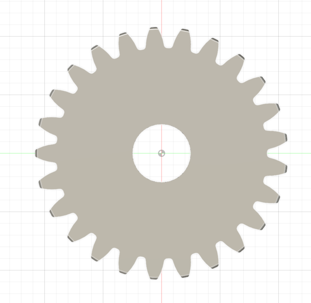
Fusion360 CAD of the gear
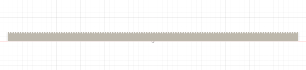
Fusion360 CAD of the rack
I was then able to laser cut these two pieces on acrylic to observe how the default teeth sizes would fit together. When cutting with the laser cutter I noticed that the rack was cut with two passes. I’m not sure if this is because of the way I exported my DXF file, but this could make the teeth on the rack much smaller than they should be. When I checked the fit between the gear and the rack, I saw that it wasn’t a good fit, as there was a wiggle room between the gear and the rack. I would like the fit to be nice, so I needed to account for the kerf of the laser. I’m planning on coming into the lab next week to re-adjust the size of the gear so it will fit better.
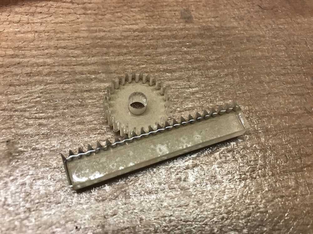
Laser cut rack and gear
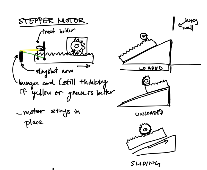
Sketches of stepper motor as slingshot
dropper ideation
For my treat dropping mechanism, I planned on using a stepper motor, so I started to think through
how I would do so. The main problem that I need to solve was storing many treats at a time and
only dropping one treat into the launcher at a time. This was a tricky problem and took lots of
thought since my treats were shaped like discs and all not exactly the same size. Like I noted
before I will use the Charlee Bear dog treat
which is about 0.5” or 12.7 mm.
The brute force approach would be to simply load the mechanism by hand each time I wanted to launch a treat. This would not be ideal because the whole purpose of this device would be to throw treats at my dog when I wasn’t around. Therefore I wasn’t planning on using this approach unless I could not think of a good way.
After some thinking, I concluded that it would be fine if multiple treats dropped to be launched occasionally, however, I didn’t want a handful of treats to be sent to the launching mechanism at a time as this could cause my launcher to jam or malfunction. I took some inspiration from the mechanics of a gumball machine and how it is designed to only drop one gumball.
This design seemed like it would make sense. I would make a disc that has a couple of indents where only one treat can fit in. I will then create a cover that will ensure only one treat gets dropped into the launcher at a time (reference the image below). I will then use the stepper motor to spin the disc ⅓ of a rotation so that exactly one treat will get dropped/loaded during a spin. To account for the different sizes of traits and to ensure that they fit nicely into the indents, I will load these treats via a tube. The tube will then be flushly over the disc. Therefore when the tube is not directly over an indent where a treat can be placed, a treat will not fall out of the tube. When the tube is over an indent, it will drop only one treat since the depth of the indent will roughly be the same depth as one of the treats I will use. Since there will be a split second where the tube aligns with the indent, there will be a high probability that only one treat drops. This will solve my problem of dropping treats into the launcher. CADing and assembling this mechanism will be a great challenge.
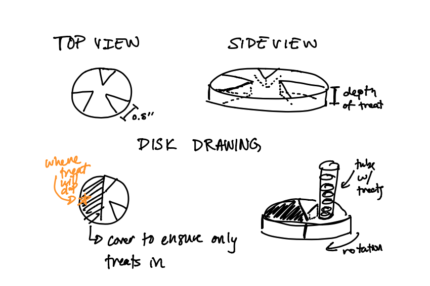
Sketches of the dropping mechanism I had in mind
One thing I also wanted to keep in mind was that this mechanism needs to be disassemblable. This is key because if the tube or disc gets jammed, I will need to be able to quickly take it apart to fix the device.
NEXT>