week 10: networking
December 2, 2020
assignment
1. design, build, and connect wired or wireless node(s)
with network or bus addresses
This week’s assignment is to communicate with a PCB wirelessly.
This directly relates to my final project and the functionality I hoped to add to my
device. Instead of using the physical button to activate all the mechanisms for my
treat launcher, I wanted to be able to do so wirelessly via my smartphone. This would
make my device much more easily used. I also dive into the different ways to connect my
final project wirelessly on my final project page.
Thankfully with some hindsight, the ESP32CAM board that I picked has built-in WiFi and Bluetooth. This allowed me to use Bluetooth without adding any additional components. My plan was to just use Bluetooth to activate my mechanisms. Therefore, I started to do some research and learned how to do so with the ESP32CAM.
One thing I quickly learned is that Bluetooth and Wi-Fi don’t co-exists very well on the ESP32 because they share the same radio system. Therefore Bluetooth connection needs to be closed as soon as the Wi-Fi connection starts to be used for data so it would be hard to integrate my camera live stream that would be over Wi-Fi. So unfortunately the Bluetooth path would only be good for getting all of the mechanisms working, but it would be much harder to integrate the camera and Bluetooth on one web application. Nonetheless, this is a great opportunity for me to learn more about Bluetooth and how to use Bluetooth with the ESP32CAM.
Working functionality I would like to emulate
I first needed to figure out how to communicate over Bluetooth from my iPhone to the ESP32CAM. I saw many others use the Serial Bluetooth Terminal on Android to send messages from their smartphone to the ESP32, however, I was using an iPhone. After having very little luck with finding an iPhone app that worked like the Serial Bluetooth Terminal app on Android, I did some more digging and found that the Arduino IDE actually has a Bluetooth Serial Monitor available for use.
I then went to Arduino and started coding. My mechanisms didn't get shipped to me yet, so I decided to just light up the LED over Bluetooth. I had to add a chunk of code I found online to enable the Bluetooth package. But once I added this, I had to add a simple if statement to check for incoming Bluetooth signals, and implemented an LED flash when it received the input “1”.
I then went to Arduino and started coding. My mechanisms didn't get shipped to me yet, so I decided to just light up the LED over Bluetooth. I had to add a chunk of code I found online to enable the Bluetooth package. But once I added this, I had to add a simple if statement to check for incoming Bluetooth signals, and implemented an LED flash when it received the input “1”.
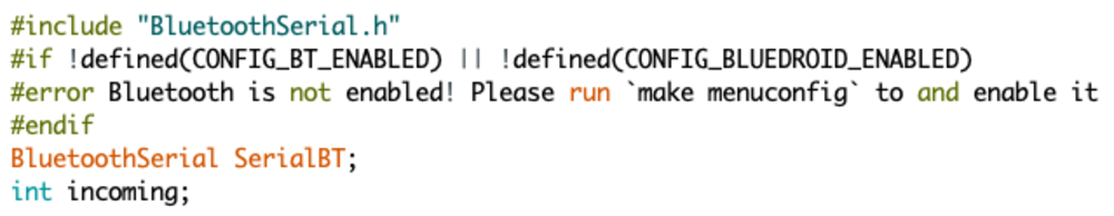
Setup code initializing Bluetooth library
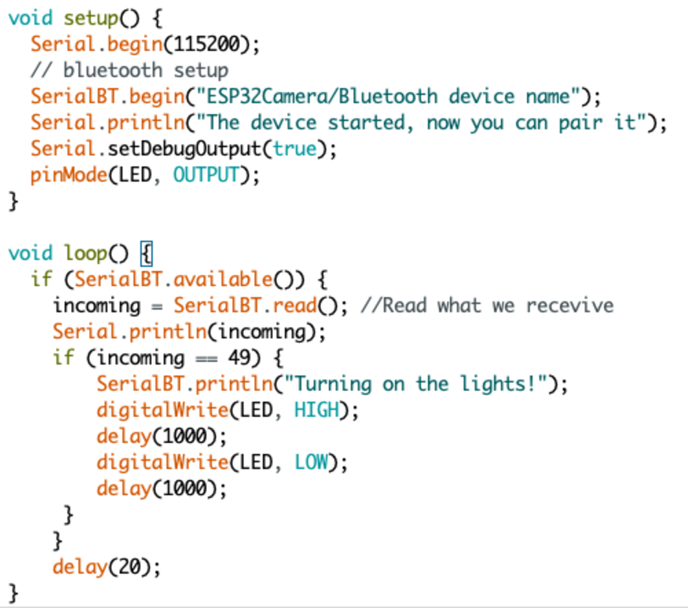
Bluetooth code to light up LED
To get the Bluetooth Serial Monitor working, I first had to upload the code above to the ESP32. I then went into my Bluetooth settings on my Macbook and found the ESP32 that was ready to be paired. Once I connected to the ESP32, it disconnected. I was confused and couldn’t, however, I did some reading online and it said that the ESP32 will not connect until it is in use. Therefore, I stopped trying to connect to the device and went back to the Arduino IDE. Under the Tools menu I went to the Port option and I selected the Bluetooth device. Mine was under the path /dev/cu.ESP32-ESP32SPP. I then opened the serial monitor like how I usually would and was able to send messages via Bluetooth!
LED lighting up over Bluetooth
The reason why I check to see if my input is 49 is because when I send 1 to the ESP32, I am actually sending over a string. When it converts to an integer, the ASCII value for “1” is 49, so that is why I am checking for 49 to blink the LED.
Although I likely won’t use Bluetooth for my final project, it was neat reading up about Bluetooth integration with the ESP32CAM.
NEXT>
Although I likely won’t use Bluetooth for my final project, it was neat reading up about Bluetooth integration with the ESP32CAM.