week 3: computer-controlled machining
September 30, 2020
assignment
1. test runout, alignment, speeds, feeds, and toolpaths for your machine
2. make (design+mill+assemble) something big
inspiration for the week
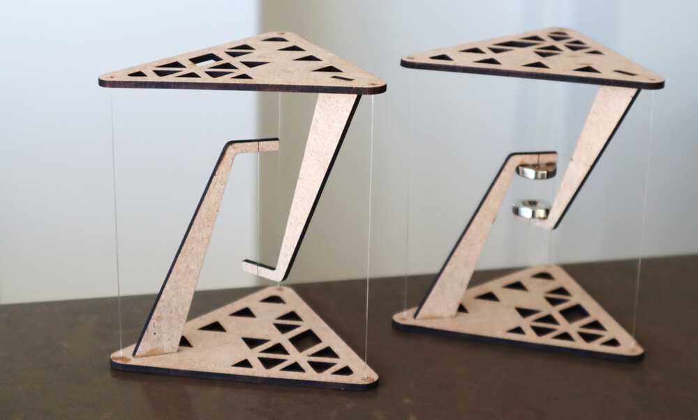
I remember stumbling across a table that looked like it was floating thanks to
“tensegrity” on the internet a couple years ago. Given my need for a night stand in my room, I
figured I’d make a tensegrity table as a night stand. Since I was curious to understand the
physics behind the table I watched this video.
Below is the table I was inspired by.
Inspirtaion for my project this week
I first talked over my idea with my section leader to see if this was a feasible
project and luckily he believed it was a viable idea. I discussed how most of the
tensegrity tables online used floss or some other weak string to hold the two pieces
together, however I knew my pieces would be larger than the pieces in the videos I watched
and the last thing I wanted was my night stand to collapse in the middle of the night.
He recommended I use paracord to hold the two pieces of the table together. Even though
the paracord wouldn’t be as aesthetic as floss, I decided it was better to be safe than sorry.
So I ordered some paracord on Amazon.
design
Before I started to CAD, I wanted to get a good idea of some parameters I could assign.
I first measured the area next to my bed to see how big I should make the base and height
of my night stand. I concluded that a nightstand with a height of 600mm and base size of
500mm would be the perfect size. Additionally as noted in class, we will be provided a 4'x8'
sheet of OSB. We also know that the thickness will be 8/12’. I made sure to include the OSB
board thickness in the parametric design because the thickness of each sheet of OSB could vary
by fractions of inches.
With this information I started to CAD my design. I planned on cutting square pieces of OSB for the base and cutting three smaller pieces to support the base. I added the supports under the base because the OSB bends pretty easily, and I didn’t want the OSB to snap or bend when held together by the paracord. The supports were rectangular cuts of the OSB board that had finger joints to connect all of the support pieces together. I also made sure that the arm that reached down crossed the center of my table so that I could feed the cord directly in the middle of the table decreasing the overall sway. Additionally, in order to ensure that the arm was sturdy enough to hold up the top half of the table, I planned on layering three cutouts of the arm and gluing them together to provide more support. Here is my CAD design:
With this information I started to CAD my design. I planned on cutting square pieces of OSB for the base and cutting three smaller pieces to support the base. I added the supports under the base because the OSB bends pretty easily, and I didn’t want the OSB to snap or bend when held together by the paracord. The supports were rectangular cuts of the OSB board that had finger joints to connect all of the support pieces together. I also made sure that the arm that reached down crossed the center of my table so that I could feed the cord directly in the middle of the table decreasing the overall sway. Additionally, in order to ensure that the arm was sturdy enough to hold up the top half of the table, I planned on layering three cutouts of the arm and gluing them together to provide more support. Here is my CAD design:
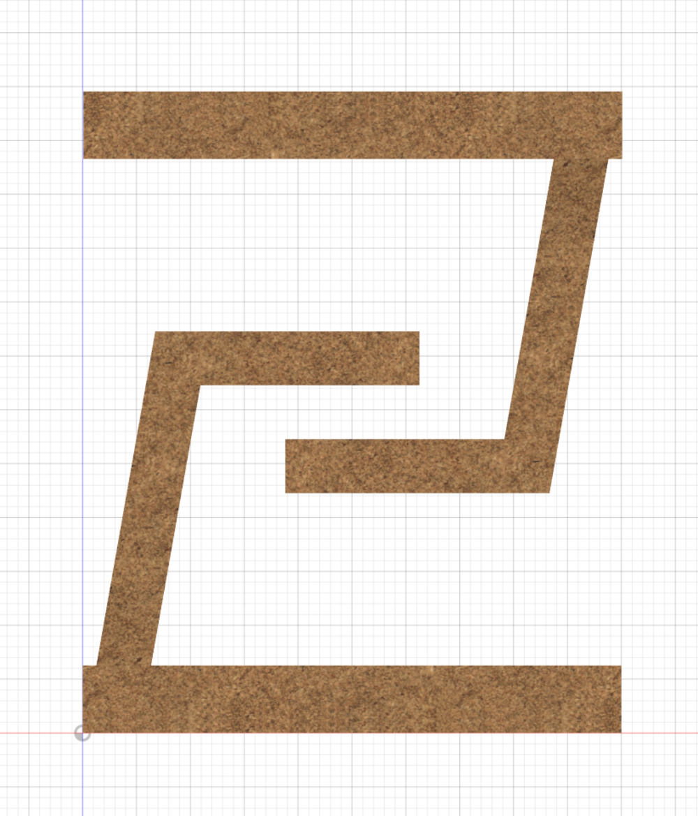
Side view of my CAD on Fusion360 (w/o supporting strings)
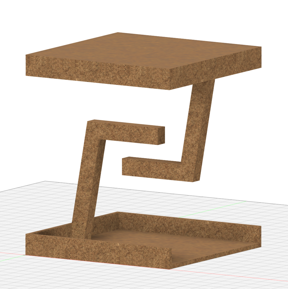
3d view of my CAD on Fusion360 (w/o supporting strings)
Next I took apart my CAD design and laid out all of my pieces on a 4’ x 8’ rectangle and
exported the sketches to a .dxf file. Then I had to create a toolpath for the CNC machine to
read so it could cut the pieces I wanted. Zain (one of the section leaders) was a huge help
with the toolpath work, as he walked through the software that converted my .dxf file into a
format for the CNC machine to read.
cutting
Before I started to cut my parts for my tensegrity table, I needed to test how well the
finger joints fit with my current design. I remembered that in the laser cutting assignment,
although my finger joints and indents were the same size, it wasn’t a snug fit. Therefore I
cut out 4 different finger joints, each with different indent widths.
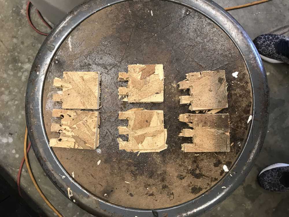
The test joints I cut out
I cut out 1 piece with indents the same width as the finger width,
2 pieces with larger indent widths (.1 mm increase and .2 mm increase), and
1 piece with a smaller indent width (.1 mm decrease) while keeping the finger
joint total width still 50 mm. After seeing how each of the joints fit, I concluded
that the joint with the indent width that was .1mm larger fit the best. I thought I
had solved all my problems and was getting ready to print, however Chris (another one
of the shop experts) brought up a possible point of failure in my design: the way I
connected the under arm to the base of my table. I was planning on using super glue
to keep the arm and base stuck together, however, he noted that the super glue wouldn’t
stick well on the cut portion of the OSB board. He recommended that I added another
finger joint between the arm and the base to help keep the arm in place (which is important
since the entire table is being held up by the arm). I took this to account and made the
adjustments to my CAD design. Now I was finally able to start cutting.
The Onsrud machine in action
Cutting all of the pieces took a little under 5 minutes, and my pieces looked good!
One side note & quick fail: my base piece got cut incorrectly at first because when we
created the toolpath, we cut on the wrong side, therefore the Onsrud machine cut in too far,
exposing the area where the finger joint from the arm should have been held. So with a
quick fix, Zain edited the toolpath and we got a successful cut.
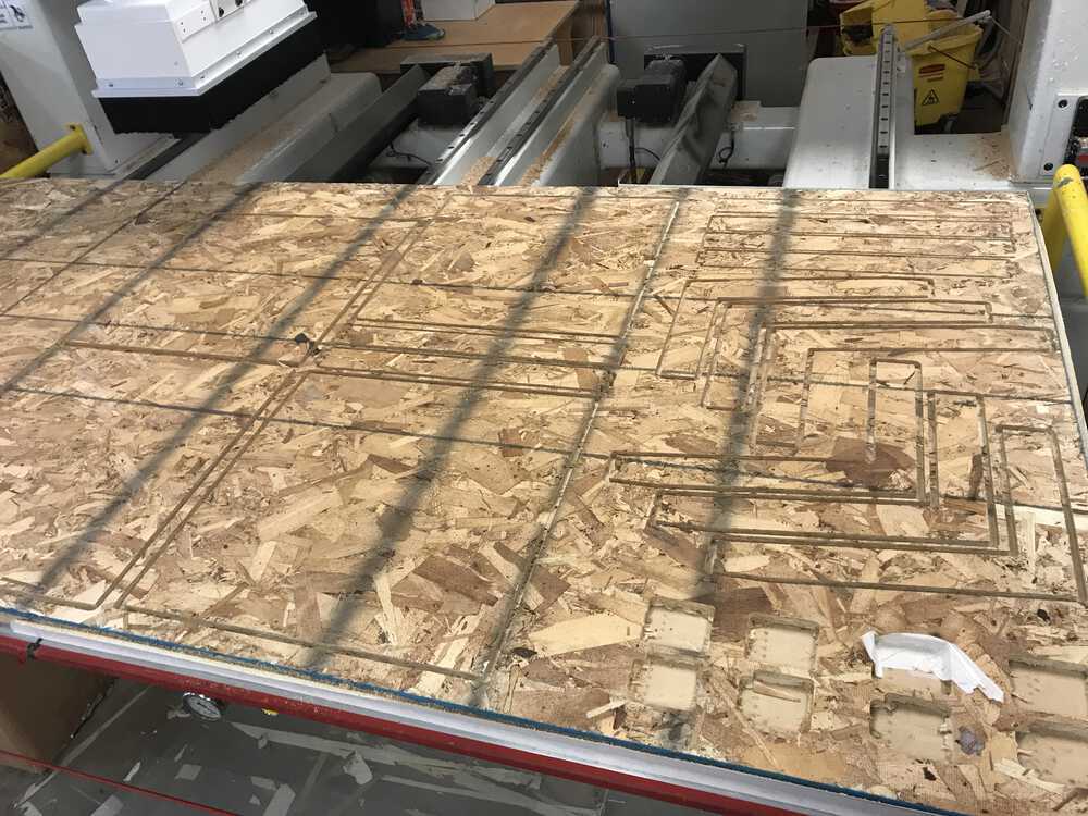
The scene after the Onsrud finished cutting
I had to use an exacto knife to cut out the pieces from the OSB board
and then filed down the edges of my pieces to get rid of the excess wood that was hanging off.
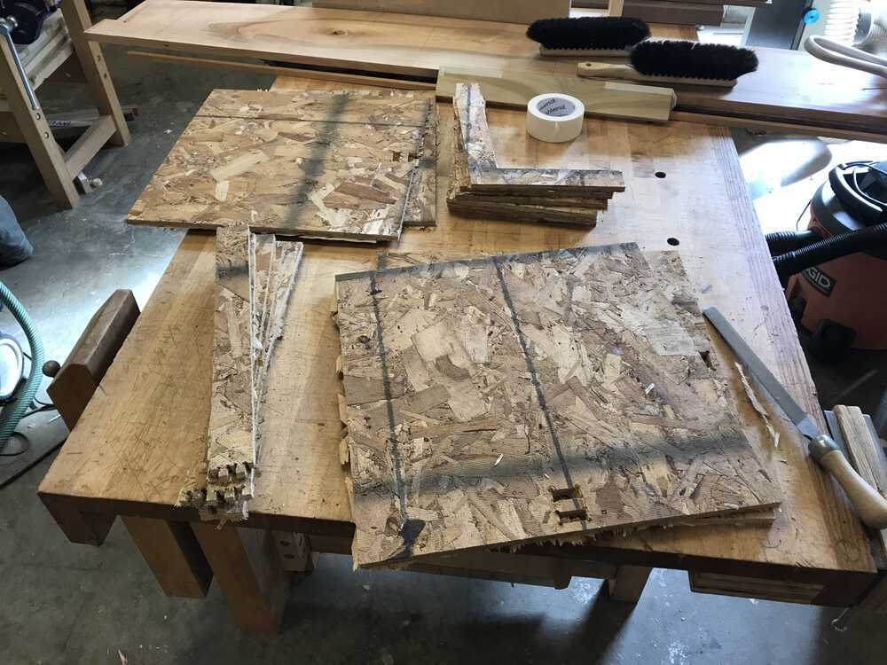
All my pieces
assembling
In order to make sure the base was attached to the support I had to glue some pieces together.
After discussing with Chris, we figured it was best to use Gorilla Glue to hold these pieces
together. I put on some gloves and rubbed a damp rag on the areas where I would be applying the
Gorilla Glue. From here I connected my three support pieces and laid them over the base. This
was nice because the base acted as a guide to ensure my support pieces were straight. I then
applied 7 clamps to keep the support in place as the glue dried. I did the same for the other
side of the base.
I also had to glue together the arms. I followed the same technique and clamped the three pieces together for each arm. I let the pieces sit overnight.
I also had to glue together the arms. I followed the same technique and clamped the three pieces together for each arm. I let the pieces sit overnight.
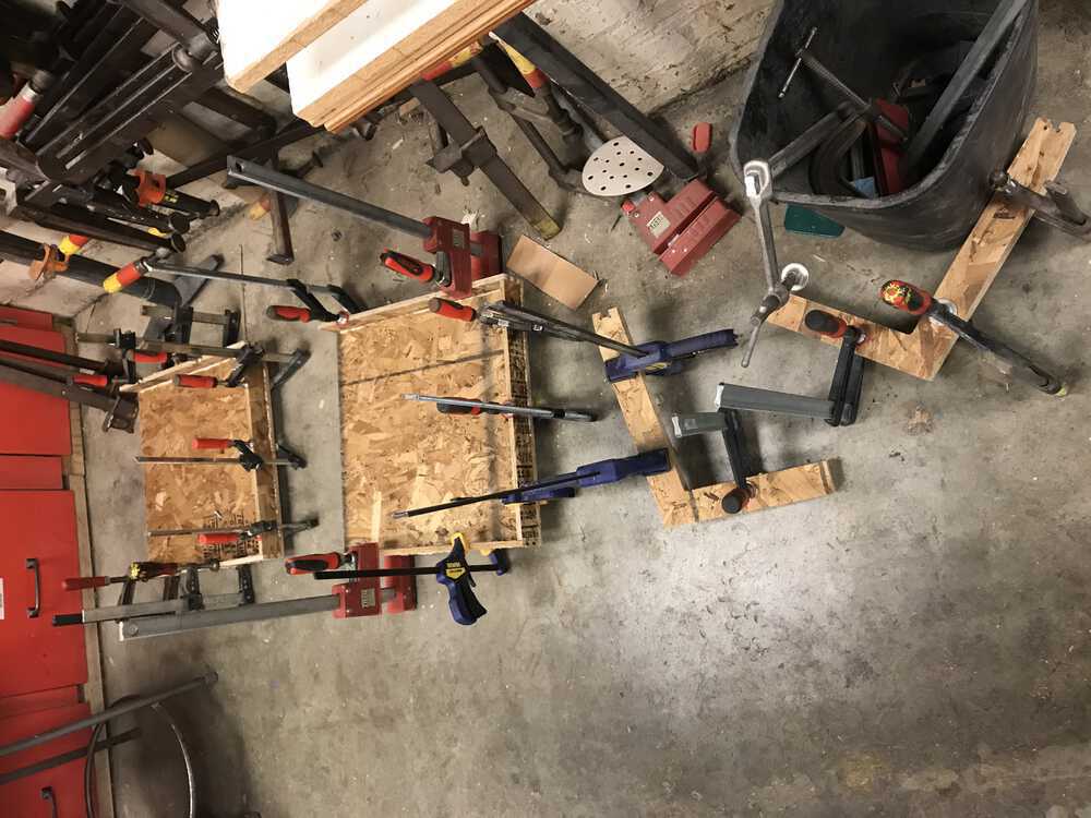
Glued pieces sitting to dry
I went to the shop in the morning and fit the arms’ finger joints into the two bases.
I also applied some gorilla glue on the back side of the arm and the finger joints to
ensure that the arm would stay in place since it would support most of the weight of the
base on my tensegrity table. I used a hammer to make sure the finger joints in the arm fit snuggly with the
finger joints on the base. I let the pieces sit for 2 hours for the glue to dry.
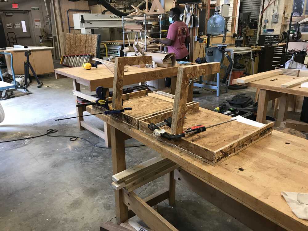
Gluing the arms to the base
Once all of the pieces dried, I did some measurements and found the center of my
base. This is important because I needed to drill the holes for the cord to be fed
through directly in the middle so my table would be stable. I found that the middle is
9.8125 inches from each edge (since the base is square). Our arm was offset by .5 inches
because of the support, so the middle of the table from the end of the arm was 9.3125 inches.
After drilling the hole, I found this was a mistake since my arm was slanted, so I overshot
the middle of my base. I had to re-do some calculations and cut a new hole that would
actually be in the center of my base.
I also drilled holes 1 inch from the end of each of the supports. These holes would be used by the paracord as support to counteract the cord going through each arm.
I then clamped the top half of my table on some plywood with the desired height. Then I slid the second half of my table underneath the top half. This would allow me to keep the table in place while tightening the cords sufficiently.
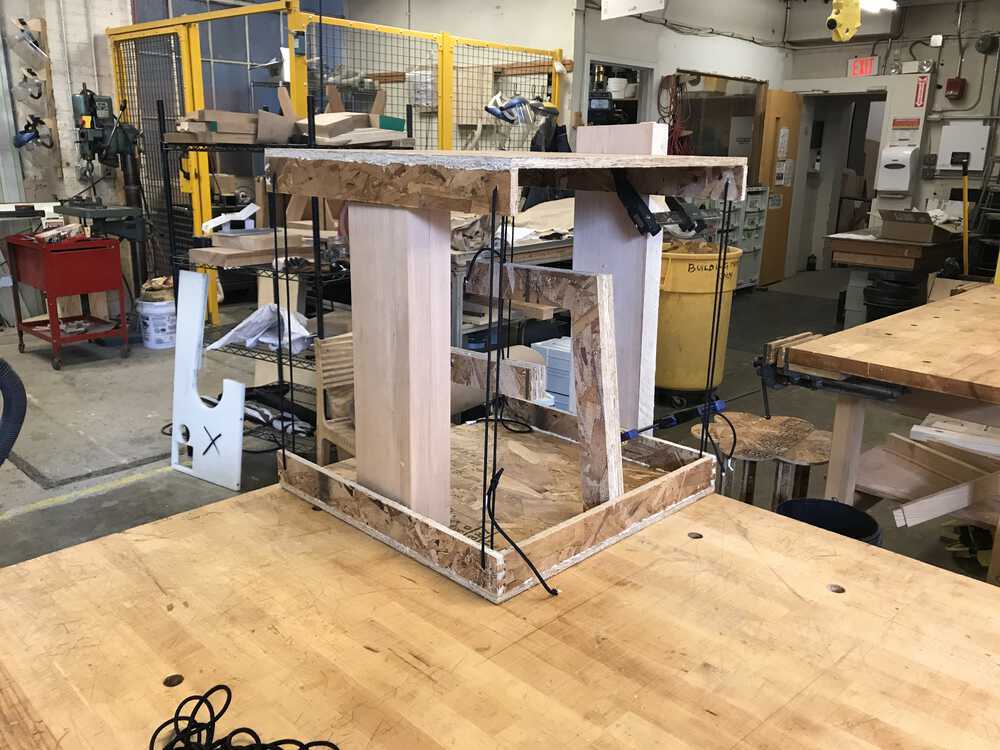
Clamping the top piece on plywood helped me figure out how tightly to tie the paracord
After the first pass it was too loose, so I planned on tightening the cords in the front of my
table. I also noticed that the back cord was useless in terms of keeping the table upright,
so I decided to remove them and just focus on the two cords in the front.
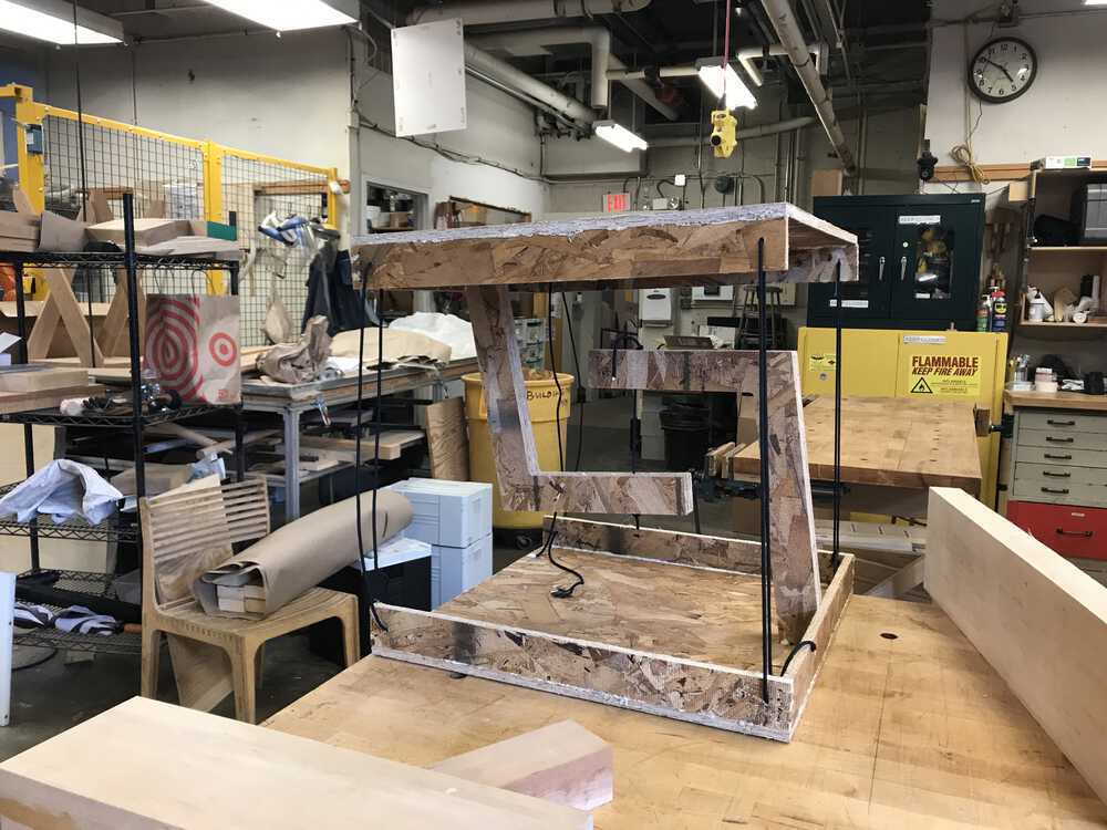
First attempt tying paracord -- too loose
Nancy helped me tie a stronger knot by tying the bowline knot.
And after some adjustments, I got the perfect tightness
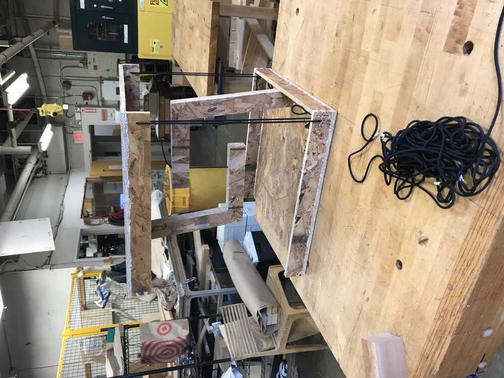
The right amount of tightness -- success!
conclusion
Overall my project for the week was a success!
I thought the coolest part of my tensegrity nightstand was when it “snaps” into place.
Demonstration of my tensegrity table "snapping"
I now have a super cool looking nightstand and have learned a lot about
computer-controlled machining. Next time, I would like to use clear fishing line instead
of paracord since it would look like it was actually floating. But I am still very happy
with my final product!
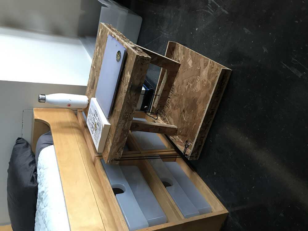
Nightstand in action
NEXT>