week 7: embedded programming
October 28, 2020
assignment
1. read a microcontroller datasheet
2. program your board to do something, with as many different programming languages and programming environments as possible
2. program your board to do something, with as many different programming languages and programming environments as possible
This week’s topic is embedded programming. I have had minimal experience with embedded programming in a previous class I took (6.08 - Intro to EECS via Interconnected Embedded Systems). In that class, we used breadboards so I was excited to learn how to do embedded programming with a PCB I created.
reading a datasheet
The first half of this week’s assignment is to read a microcontroller datasheet. I chose to read over the ESP32 datasheet. I chose to do so because I am planning on using the ESP32 for my final project. This datasheet was 54 pages, and I didn’t understand all of the content, however, with some Googling, I was able to understand some parts of the datasheet. The ESP32 seems like a good choice for my final project because of its use for Internet-of-Things applications. Given it is a highly-integrated solution for Wi-Fi-and-Bluetooth IoT applications, this is helpful for my use cases (camera, audio, connection to a remote).
programming my board
Now it was time to start programming my board. I first wanted to test out my custom PCB I created last week to see if the LED lit up. I grabbed the serial adapter and the jumper wires and hooked up the adapter to my PCB. I then plugged in the serial adapter to my PCB and expected to see an LED light up, however, I saw nothing.
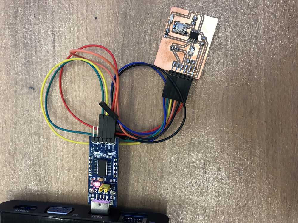
No blinking when I connected my PCB to the serial adapter
I thought I definitely should have seen an LED light-up because there was an LED that was directly connected to VCC so I thought this could be an issue with the way I soldered or set up my board. Therefore, I printed out the ATtiny412 blink board that was on the HTMAA website. After soldering all the components, I then followed the same procedures as before and waited to see if the LED lit up and it didn’t. So I went into the lab to meet with Anthony to debug my issues.
After going into the lab, I was able to get more contextual background and I started to understand my problems. The reason why the light wasn’t turning on was that my LED wasn’t connected to GND, but to the pin PA2. This is causing the problem because I need to set PA2 in my code to transmit low in order to cause the LED to light up.
Also, the serial adapter’s main purpose is a translator, so that is why we can’t directly connect our PCB to our computer. Lastly, my board was showing up, it was just named something different than what was on Zach’s tutorial. With all these problems sorted away, I was ready to start programming my PCB.
Before I started, Zach’s tutorial on programming the ATtiny412 was extremely helpful. I first downloaded the megaTinyCore board in the Board Manager built into Arduino’s IDE. I then copied over Professor Gershenfeld’s original blink code for the ATtiny412 to do a simple test. To easily locate the hex file, I edited my preferences text file to include the path to save all my built hex files. We will use these hex files when we use pyupdi. Once I finally identified my USB port (by looking at the tools → port option in the Arduino IDE) I ran the pyupdi command.
This originally didn’t work as I ran into many issues with dependencies. However after some debugging with Erik, there was an issue with the multiple versions of Python I had on my computer so my dependencies weren’t installed in the right location.
I had to manually set the location of where my pip install would place the dependencies with this command: `pip3 install --target=/Library/Frameworks/Python.framework/Versions/3.7/lib/python3.7/site-packages .`
Now I was able to run the script on my PCB!
Base ATtiny412 blink board in action
Custom ATtiny412 blink board with 2 LEDs in action
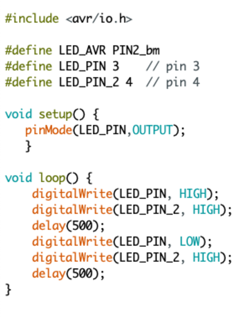
Code that causes two LEDs to light up at different times
I then experimented with increasing the delay time and the LED blinked at a slower rate. Notice how I put both pins to output high but the lights are alternating. This is because the pin with the dimmer light is outputting high voltage which powers the LED. However when the other pin outputs high, it prevents the circuit from flowing, therefore it doesn’t light up.
I had also messed up my board from last week by not putting the button in between the resistor and the pin so my button press code did not work.
The overall procedure to run the script on the PCB is Verify the code on the Arduino IDE, go to the location of the hex file, run the pyupdi.py script with the correct flags (-d chip -c USB port -b baud rate -f hexfile) and the program should run on the PCB!
a new board
Since I didn’t have the opportunity to mill a custom PCB on the clank, I wanted to do so this week. I had the idea of creating a PCB that would light up in different ways when a button was pressed. I also wanted to create one of the echo boards that would speak back to you when you type in inputs.
So I started off with designing a new PCB in Eagle with the ATtiny1614 which was a different microcontroller than the one I originally used. I then added all of my components and passed by my PCB board design by Anthony. Once I got the okay from him, I exported my PCB as a png and started to cut my PCB with clank.
So I started off with designing a new PCB in Eagle with the ATtiny1614 which was a different microcontroller than the one I originally used. I then added all of my components and passed by my PCB board design by Anthony. Once I got the okay from him, I exported my PCB as a png and started to cut my PCB with clank.
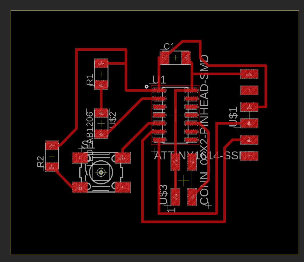
Board diagram from Eagle for my custom PCB
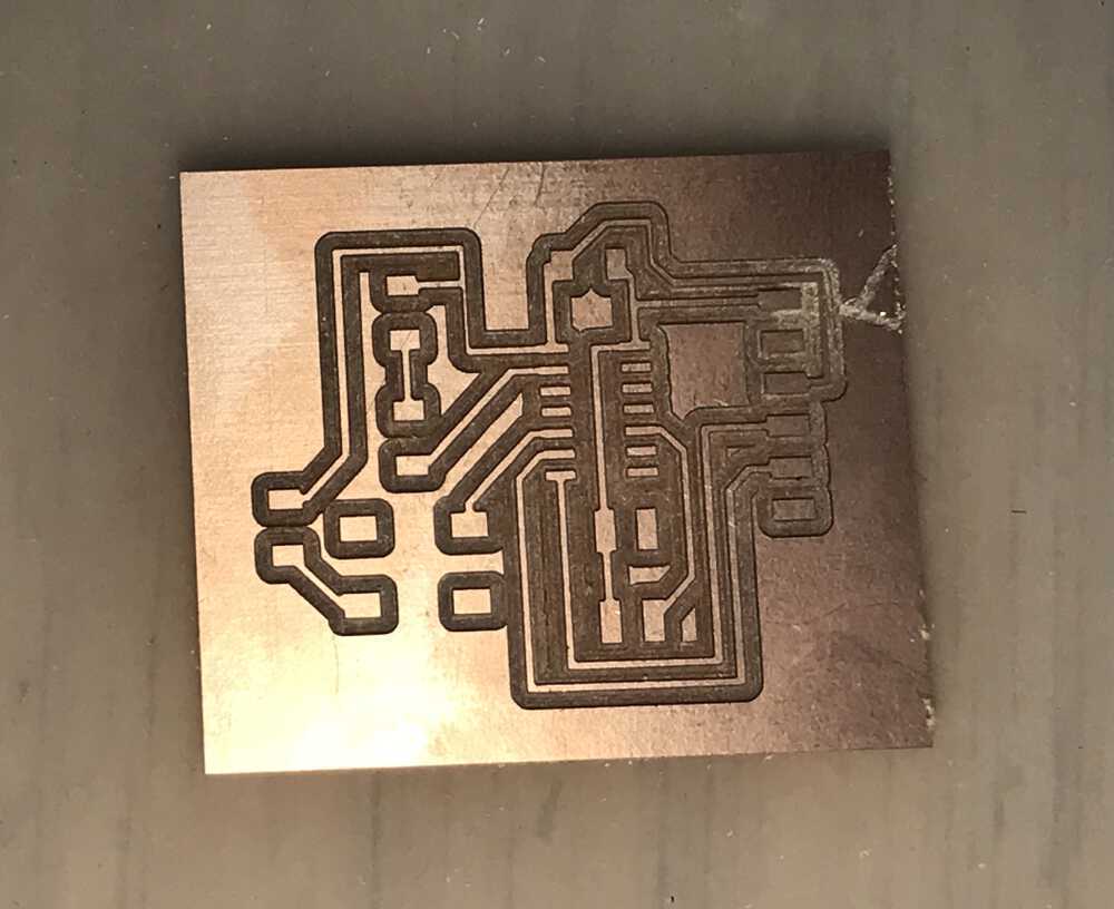
Traces of my custom PCB
For my first time going through this process, it turned out pretty good and went smoothly. I then soldered all of my components on my PCB.
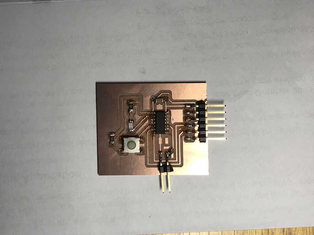
Finished custom echo and blink ATtiny1614 PCB
Now time for some programming. I again used Professor Gershenfeld’s starter code to get the echoing functionality done, however I modified it and wrote the button/LED activation code myself. I thought this would work however it didn't. I wasn't getting any printed output from my PCB.
When I took it to the lab to get debugging help with Anthony we couldn't seem to find the issue since there was VCC we detected from the multimeter. However we saw I ran the pyupdi command incorrectly and set the `-d` flag to `tiny412` when I was working with a `tiny1614`. This may have caused my problem so I took off the microcontroller and tried again.
After I re-soldered a new ATtiny1614, I ran into some issues as some copper traces fell off. So I need to do a quick repair with some wire which you can see in the video below. Unfortunatley it still didnd't work when I programmed my board. While debuggin you can see I got the LED to light up when I manually passed in power but will go into the lab again to get some additional debugging help this week.
Custom ATtiny1614 echo and blink board
I spend a good amount of time debugging my board with Anthony. Everything seemed to look with my traces. We first tested if the pins were outputting the correct voltages. We picked some random pins and outputed either high or low and used the multimeter to measure the volatges. An odd thing we noticed was even though we alternated the voltage from the pins from high to low, the voltages stayed high. When we switched them to do the same but in the opposite direction, we saw the voltages outputed stayed low. This was confusing and thought there was something wrong with the internal clock of the ATtiny1614.
We tried using `_delay_ms` from delay.h instead of `delay` and it has even weirder results where it works for 4 or 5 cycles then hangs. Then I got some errors saying I couldn't program my board. Frustrated and out of lab time, I went home and tried it again. This time I wanted to ensure that I could program my board, so I tried programming my ATtiny412 board which worked. I then switched back to the ATtiny1614 which I had trouble with and forgot to switch the board to ATtiny1614 in the Arduino IDE. I still tried programming the board which obviously didn't get the code working, but quickly realized my mistake and changed the settings to take into account the ATtiny1614.
I also decided to use the FTDI-UPDI board that I cut to program the board, and it started to work! I really don't know what I did but my board was able to run my code. So I experimented with the echo code and did some cool features with the button. However my favorite was making the button light up everytime I typed something into the miniterm.
Custom ATtiny1614 blink and echo!
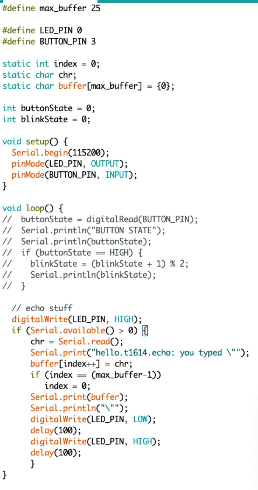
Code for my custom echo board
Overall I learned a bunch this week, and I look forward to further experimenting with different components and diving into embedded programming more. This will be particularly useful for my final project. I'm hoping to fix my PCB soon
NEXT>