week 8: input devices
November 4, 2020
assignment
1. measure something: add a sensor to a microcontroller board that you have designed and read it
In lecture this week, Professor Gershenfeld discussed input devices. He covered lots of very cool sensors we could add to our circuit boards including motion, light, acceleration, temperature, and sound sensors. He also talked about the ESP32-CAM, which I will be using for my final project.
Since the ESP32-CAM is more built in, I decided to experiment with building something from scratch to improve my Eagle skills. Therefore I set out to play with the sound sensors. My idea is to flash LED lights to the beat of whatever music/sounds it detects.
Since the ESP32-CAM is more built in, I decided to experiment with building something from scratch to improve my Eagle skills. Therefore I set out to play with the sound sensors. My idea is to flash LED lights to the beat of whatever music/sounds it detects.
electronics design
To start, I looked over some of the past examples on the HTMAA 2020 website for inspiration. Particularly, the board with the analog sound sensor was very helpful. I launched Eagle and I started designing my board.
Despite the shop having some ATtiny45s (which the board Neil made was based off of), I decided to use the ATtiny412. I figured it was a good opportunity to become more familiar with reading datasheets when converting the board design from the ATtiny45 to the ATtiny412. I then had to redirect some traces to different pins on the ATtiny412 to ensure it would work like the old design.
I also noticed that I no longer needed to use the ISP pins to program the board, and I added a UPDI connector to connect my UPDI programmer. Additionally, I didn’t need to include the voltage regulator since the voltage I would be providing from my USB would be 3.3V and the voltage regulator would be useless. Lastly, the capacitors and resistors near the bottom of the schematic that connected to the ISP pins were also not needed. So after some time arranging all of my components, I got my board all created and ready to cut.
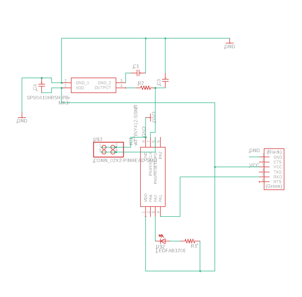
Schematic of my custom sound board
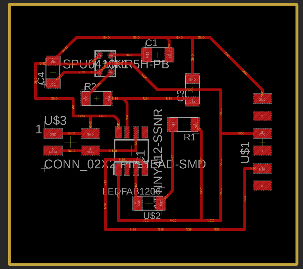
Final draft of my custom sound board
This week I milled my board on the clank. Because the bed isn’t very flat near the front of my clank machine, the initial traces didn’t seem deep enough, so I stopped the current job and restarted in a different location. Doing so allowed me to make a deeper cut.
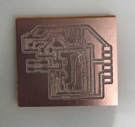
My PCB milled by clank
As you can see, the traces aren’t very clean and this could be for many reasons but I’m suspecting my end mill wasn’t in tight enough and the end mill may be getting a little dull. Nonetheless, the traces all seemed connected so I started to solder.
Most of the parts were parts I have soldered before except the MEMs audio sensor. This was an odd thing to solder since it didn’t have any extruding pins, but rather connectors on the bottom of the sensor. Since I was in the lab, I decided to use solder paste to make this process easier. Solder paste is metal solder in a putty like form that would melt and connect components to PCBs when the hot air gun was used. This was helpful in my case because the connectors were on the bottom of the audio sensor.
Most of the parts were parts I have soldered before except the MEMs audio sensor. This was an odd thing to solder since it didn’t have any extruding pins, but rather connectors on the bottom of the sensor. Since I was in the lab, I decided to use solder paste to make this process easier. Solder paste is metal solder in a putty like form that would melt and connect components to PCBs when the hot air gun was used. This was helpful in my case because the connectors were on the bottom of the audio sensor.
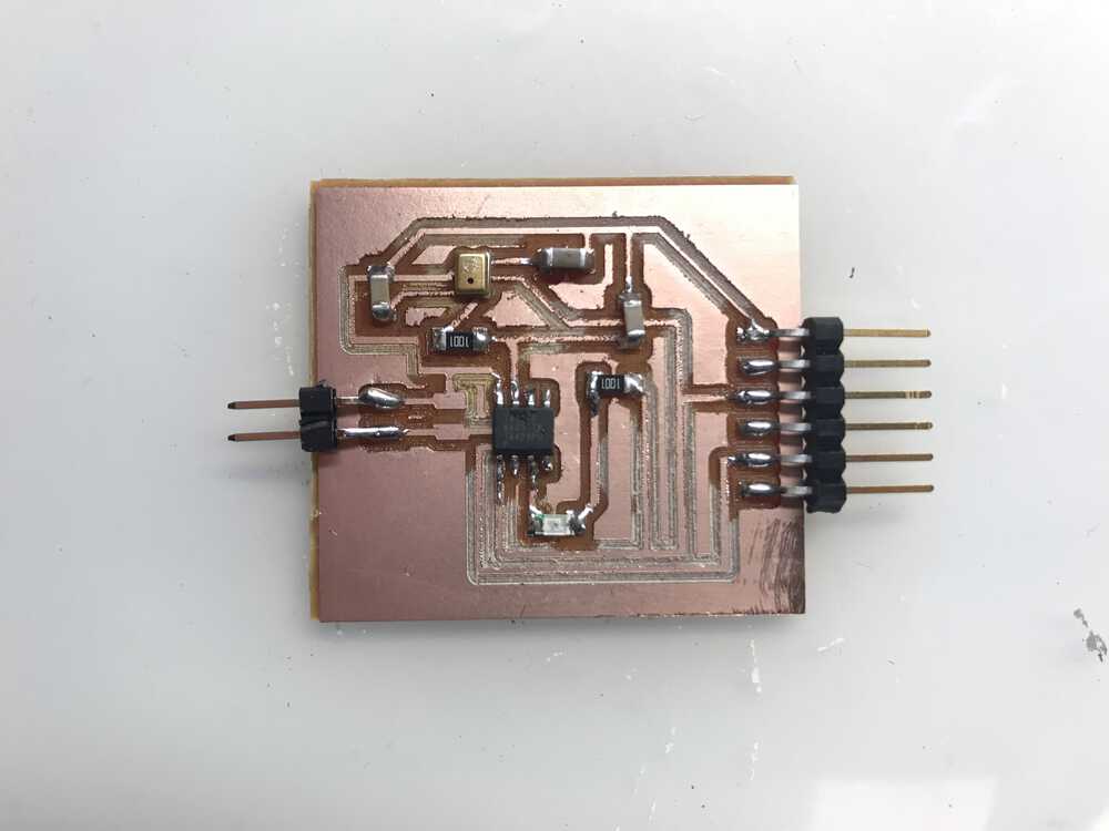
My PCB after soldering
Now it’s time to write some code to program my board.
embedded programming
I started off with some simple code that would indicate if my audio sensor was indeed working. To do so, I wrote code that would blink my LED and print the sensor value that I was reading.
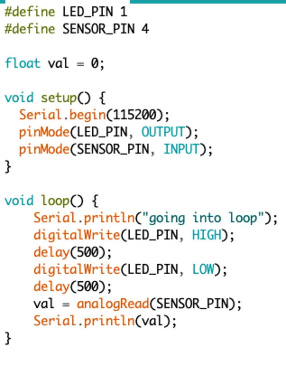
Original base code to see if sensor is working
Unfortunately, I ran into the same problem I had last week and could not program my board as the LED didn’t flash and just stayed on.
Suspecting that the way my computer was building hex files was the reason why it wouldn’t work (given last week compiling my code on another computer solved the problem), I had to download a Virtual Machine (I used VirtualBox) and tried to create my hex files from there. However, it didn’t seem that it helped as my board still wasn’t programmed correctly.
The next morning after tireless debugging, I tried to program my board and it worked! I was getting a blinking LED which was great. However, when I tried to look for the print statements when running miniterm, I didn’t see anything. This was problematic. I had no indication if my sensor was working or not. I ensured that my traces were connected prior to soldering and re-soldered the pin where RX was connected. This didn’t seem to help so I took my board into the lab to get debugging help.
After going to the lab and checking all of my traces, Anthony was able to fix my problem. For my board, I attached TX to the 3rd pin of the ATtiny412. Little did I know is that pin 2 is the default output pin while pin 3 is the secondary output pin. To fix this I just needed to add `Serial.swap(1)` to set the mapping to the alternate pins, and after this fix, my board was finally outputting text!
This means that my audio sensor was soldered correctly. Now time to play around with the sensor. One thing I learned was to use the Serial plotter on the Arduino IDE. This is helpful for working with sensors since it will plot continuous values.
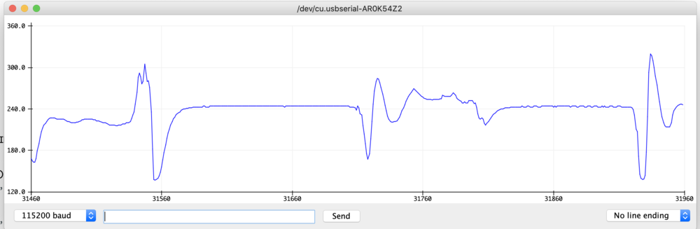
My serial plotter in action plotting real-time sound output
Also, I learned that the output I get from my sensor is ultimately a bucketed value, and in order to get the correct voltage that the sensor was outputting, I would need to multiply it by the voltage going in (which is 3.3 in my case). However, since I didn’t care much about the voltage and only the relative value to keep track of large values, I didn’t do this step.
After experimenting with my sensor, I decided to pivot and make a clapper (yes, like the infamous “clap on clap off” clapper). This was due to the fact that my audio sensor would just detect a larger value when detecting music, and not necessarily detecting bass. This wouldn’t be nice as my light would be on 100% of the time music was playing and not as dynamic as I envisioned.
After experimenting with my sensor, I decided to pivot and make a clapper (yes, like the infamous “clap on clap off” clapper). This was due to the fact that my audio sensor would just detect a larger value when detecting music, and not necessarily detecting bass. This wouldn’t be nice as my light would be on 100% of the time music was playing and not as dynamic as I envisioned.
final product
The clapper worked and it was great seeing things work given all the problems I ran into this week. I set the threshold sound to turn on or off the light to be 225 since I noticed the noise level of the room I was in was usually around 200. I also used the `digitalRead` function to read if my pin connected to the LED was on or off. This was helpful because I could see what state I was in and I could decide if I needed to turn the LED on or off by outputting LOW or HIGH respectively.
Demo of my clapper turning the LED on and off
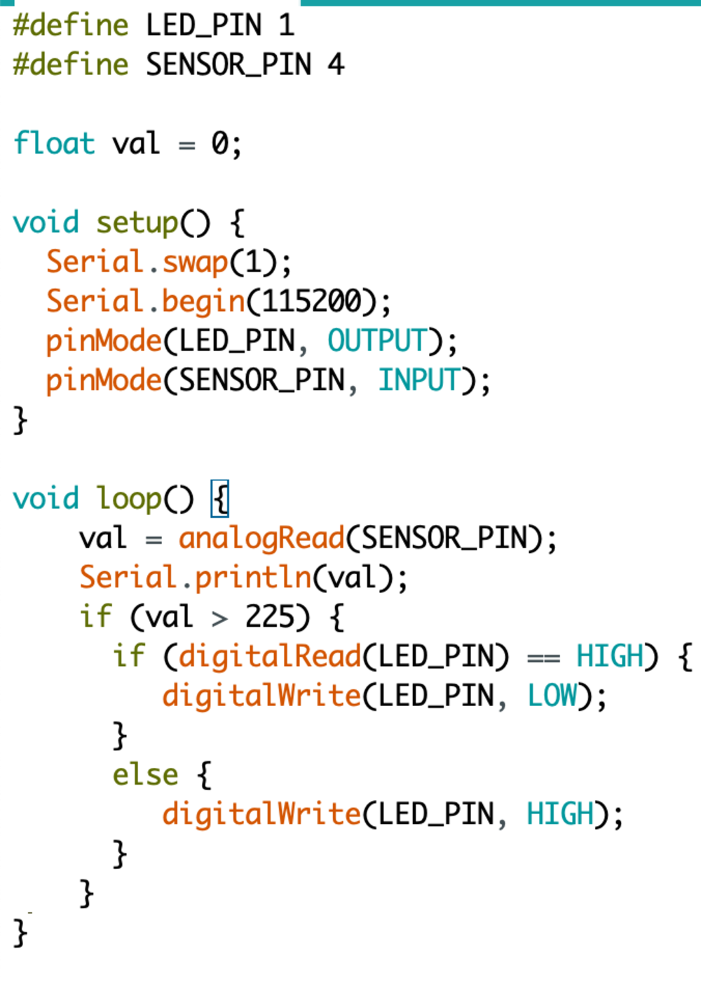
Clapper code
Although I won’t use this board or sensor for my final project, it was good learning more about input devices, the output that they provide, and more debugging tips that will definitely be helpful when I work on my boards for my final project.
I've also become much more familiar with the workflow of designing a PCB, milling it with clank, soldering, and programming it.
NEXT>