week 9: output devices
November 18, 2020
assignment
1. add an output device to a microcontroller board you've designed,
and program it to do something
Output devices week is particularly important to me because my final project includes
lots of output devices. Therefore, this week (technically two weeks due to Veterans Day) was
devoted to working with different output devices for my final project so I would know how to
code/design these components when it came time to use them for my final project.
I go into much more detail about my journey through these output devices here and here
while this page here will outline what was done for this week's assignment.
But I experimented with a solenoid, stepper motor, and speaker.
solenoid
The solenoid was of interest to me because I needed a mechanism to launch dog treats and in lecture, Professor Gershenfeld recommended that I use a solenoid as my means of launching the treats. I was determined to work with the solenoid and test it out, given the timeframe I had. So I first went into the shop and Anthony helped me assemble my own solenoid!
The process was pretty straightforward. At the eds shop, they had a mechanism that would hold the magnet wire in place while allowing it to spin. So I attached some magnet wire to a spool and attached it to an electric drill. When I powered on the drill, the magnet wire would spring around the spool. I continued this process until the spool was full.
The process was pretty straightforward. At the eds shop, they had a mechanism that would hold the magnet wire in place while allowing it to spin. So I attached some magnet wire to a spool and attached it to an electric drill. When I powered on the drill, the magnet wire would spring around the spool. I continued this process until the spool was full.
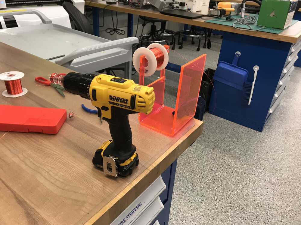
My set up to create a solenoid
After my solenoid was created, I was able to test it on the digital bench. I passed in 9V and 2A of current and was able to watch the solenoid in action. I noticed that with a magnet attached to the screw, the screw would pop up much more thanks to the solenoid.
Demo of my solenoid working
Now that I had my solenoid created, I started to work on the board. I started designing a new board from scratch, however, I had some features in mind. I wanted the solenoid to launch with the press of a button. With this in mind, much of the design has become significantly easier with practice.
One new thing I had to consider is that there is a significant inductive load when the solenoid is turned off. Therefore I need to attach a diode from the end of the solenoid back to the beginning of the solenoid. This will transfer the magnetic energy to the diode instead of breaking down the MOSFET. I also used the large N-channel MOSFET to play it safe.
Lastly, to provide sufficient current to the solenoid, I designed my board to also take in a power supply from a 9V battery. I was advised to increase the size of my traces that would carry more current, so my new trace size was 30 mm instead of 16 mm.
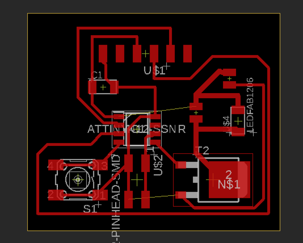
Eagle designed board for the solenoid
With my board all set up, I then milled and soldered my board.
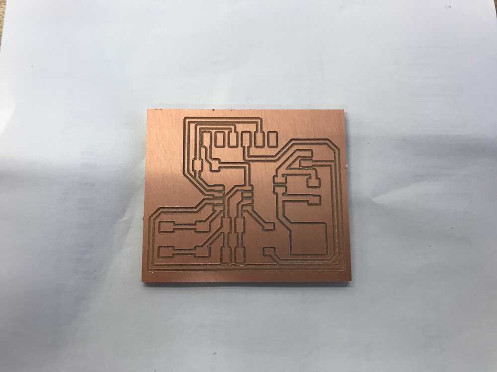
Traces for solenoid board
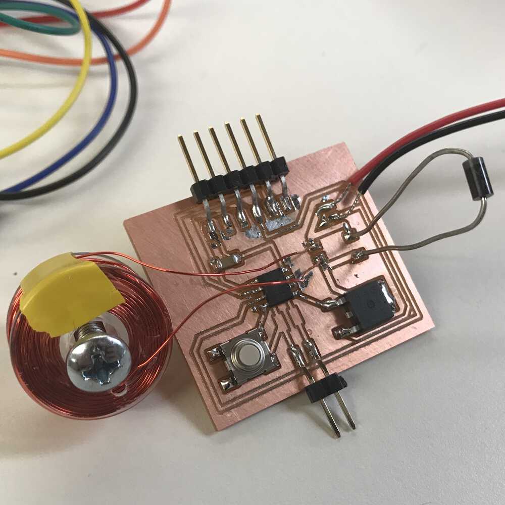
My PCB after soldering
To let current flow through the MOSFET, I had to send a high output from my ATtiny412 pin to the gate of the MOSFET. Therefore, the code to get the solenoid working off of a press of a button was pretty easy.
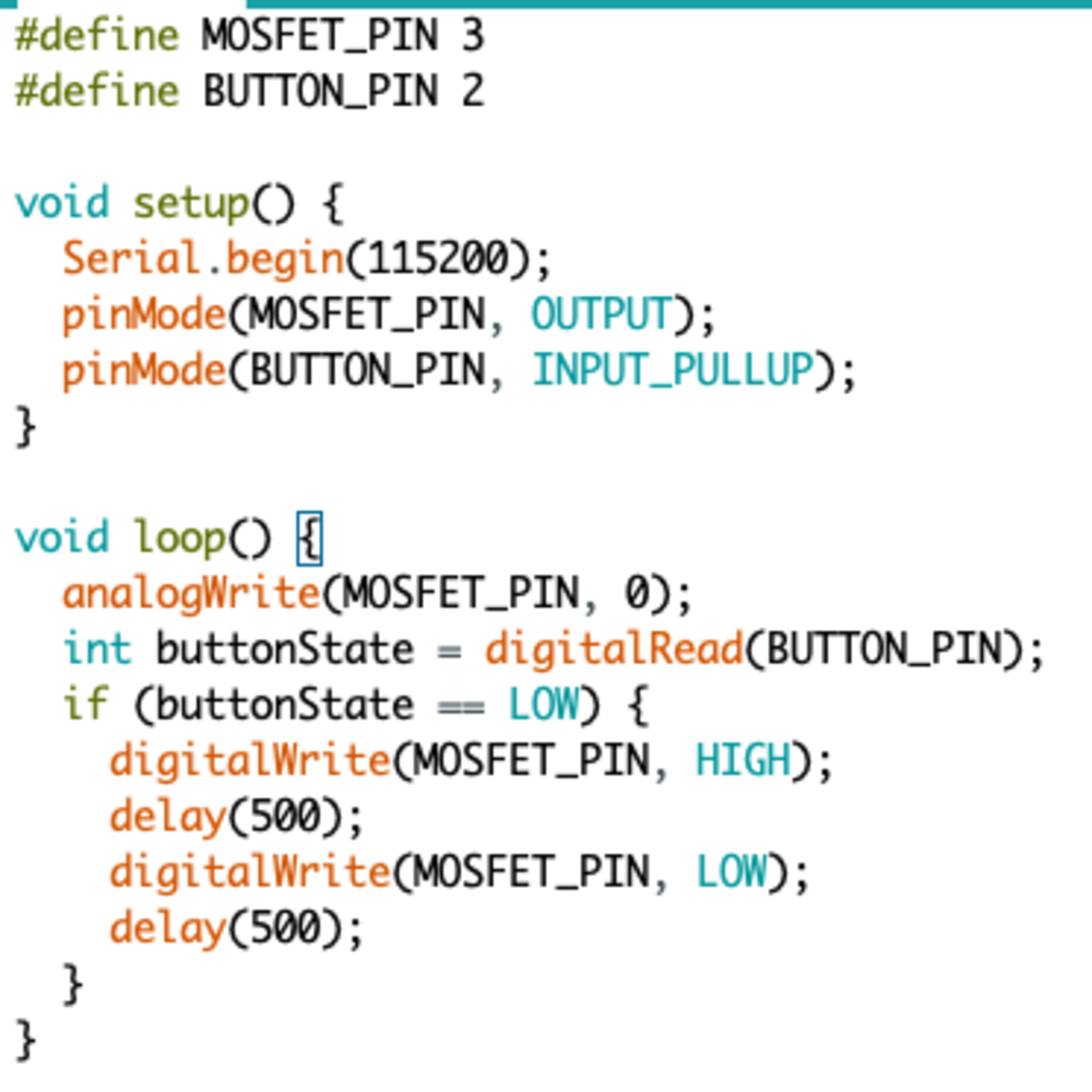
Code to launch my solenoid with a button press
Soleonid launching on button press
stepper motor
The next device I wanted to work with was the stepper motor. The stepper motor is particularly helpful since it can control a spin without feedback. I would use this in my final project because I need a device that can do exactly one rotation -- the stepper motor is perfect for my use case.
I again started to design a new board from scratch. For the stepper motor, I would need to use 2 H-bridges to control the bipolar stepper motor. This took a little more thought when designing, however, Professor Gershenfeld had an example with an older version of the ATtiny on the website, so I used it for reference. I also used the ATtiny1614 due to the additional pins I needed.
I again had to use a 9V battery and finished up with my design.
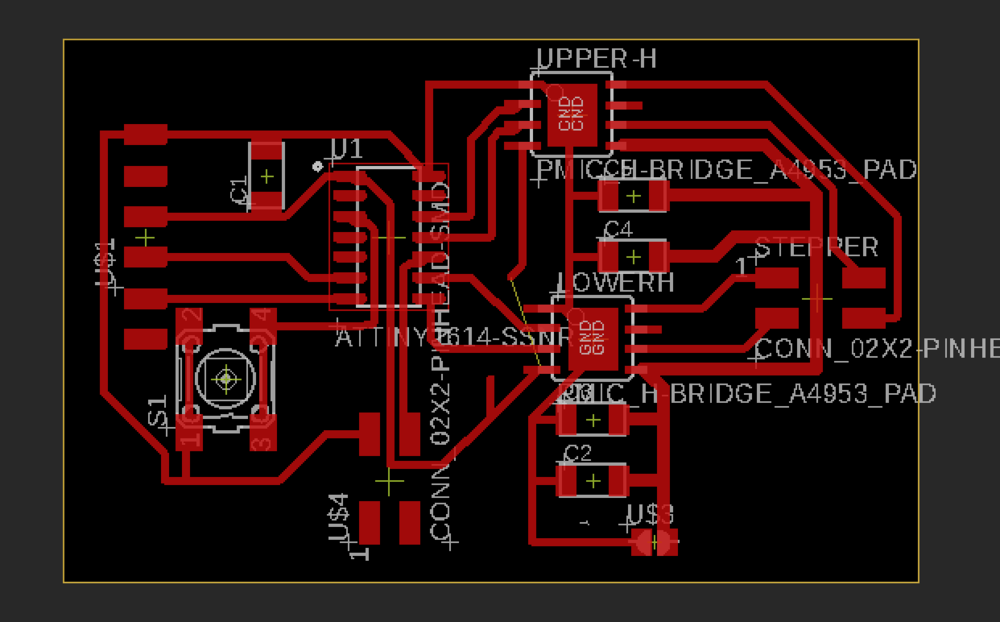
Custom board for my stepper motor
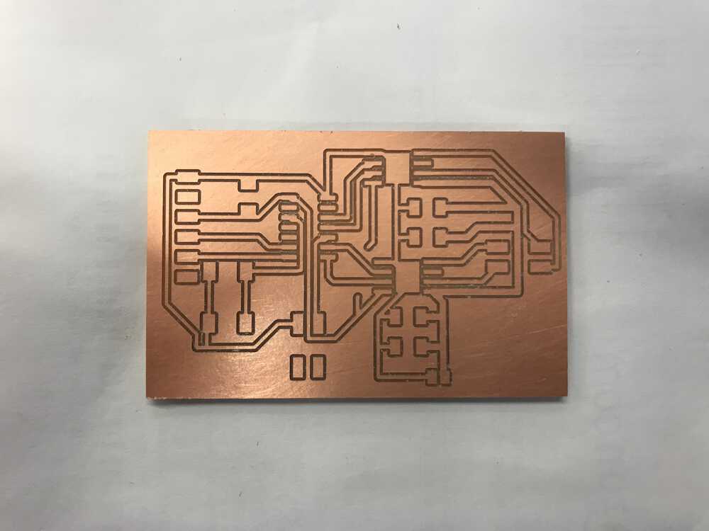
Traces for my stepper motor board
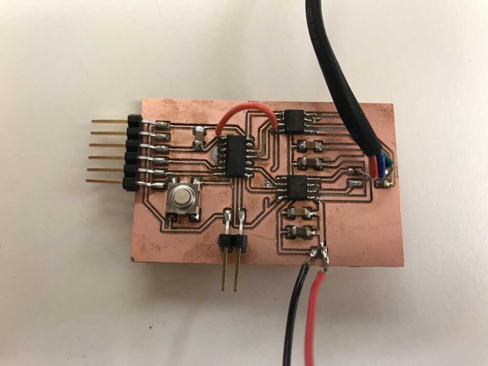
Soldered stepper motor board
Like the MOSFET, I would need to send high outputs from my ATtiny to the H-bridge. Also, for the stepper to work, each wire should be activated at a time with all of the other wires not activated. One thing I failed to do was find out the order of the colored wires on the stepper motor. Without the correct order, the stepper motor won’t work. I failed to do this and had a hard time debugging. However, Anthony was able to help and he was able to figure out the wire order by using a breadboard. The order for my stepper motor was green, blue, black, red.
Unfortunately, I still ran into many issues when debugging this board. I used both the Stepper.h library and manually coded the logic, however, the board didn’t work.
Luckily, Anthony was able to debug the stepper motor and saw that the coil resistance of the stepper is low enough that the H-bridge detects the coil as a short and doesn’t apply power. He tested this by running a resistor in series with the coil and it worked! However the resistor burnt up, so he decided to use a power resistor which ended up working. These got pretty warm when in use, however for my final project my stepper motor will only be on for a short period of time. Therefore this solution should be fine for now. He also ordered some stepper drivers to hopefully solve the issue. Below are snippets of the code I wrote (which should work with a working H-bridge).

Code that should make the stepper motor work
speaker
I wasn’t planning on making three boards this week, but I wanted to use a speaker for my final project. Lucky for me, eds had lots of spare speakers, so I was able to experiment with the speaker on a breadboard. I tried a few different approaches to see how loud the audio was. I first passed 3.3V to the speaker and the audio was very quiet. Passing int 5V and 9V helped with the volume, however, it still wasn’t very loud. When we introduced the MOSFET, the speaker got much louder and was extremely noticeable.
Once I got a good volume level, I started to play around with the frequencies I could emit. I simply toggled through the different frequencies and was able to make a bunch of different tones. This form of emitting noise is not optimal, however, for my use case, I just need to emit a series of high pitched noises. It was really nice being able to play around with all of the components I would use for my final project.
Once I got a good volume level, I started to play around with the frequencies I could emit. I simply toggled through the different frequencies and was able to make a bunch of different tones. This form of emitting noise is not optimal, however, for my use case, I just need to emit a series of high pitched noises. It was really nice being able to play around with all of the components I would use for my final project.
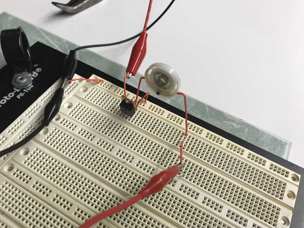
Set up of speaker experiment with breadboard
NEXT>