Electronics Design & Programming
Drawing | Schematic:
Following the examples on the website I draw the layout and labeled the components by hand was helpful to understand how it would translate to Eagle.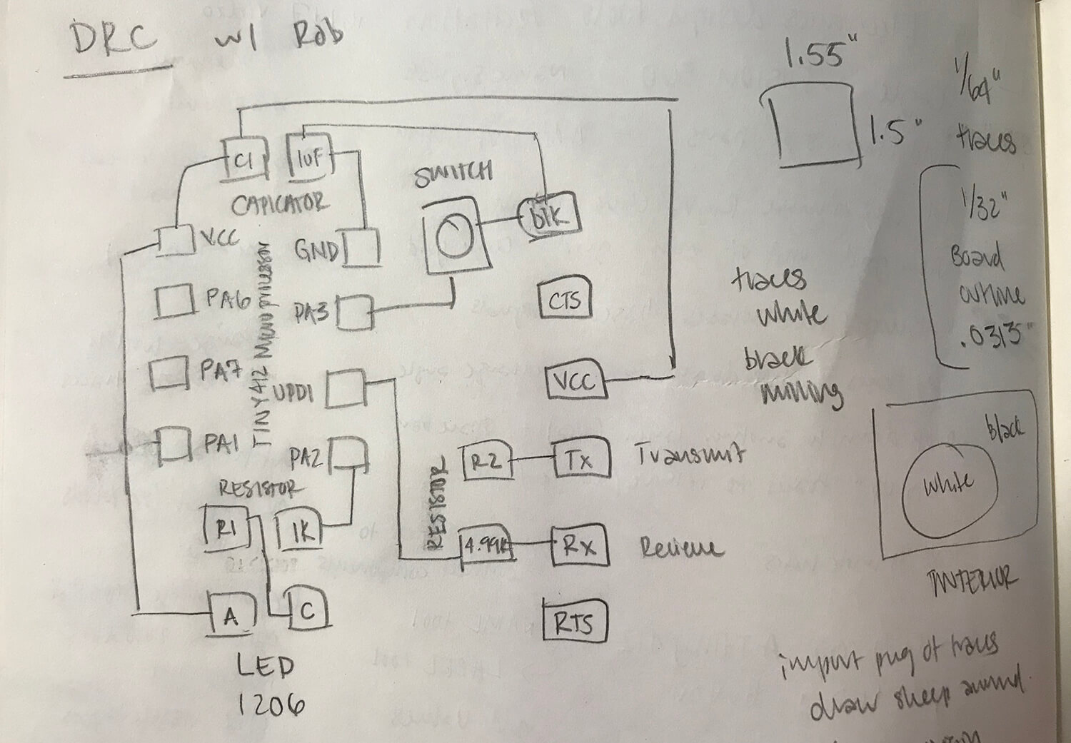
Eagle | Schematic:
I chose to build off of the ATtiny412 microprocessor adding a switch and an LED. I followed the Recitation and Sparkfun tutorials to learn Eagle and worked with Rob to design the board, we used the footprint of the ATtiny45 in place of the ATtiny412.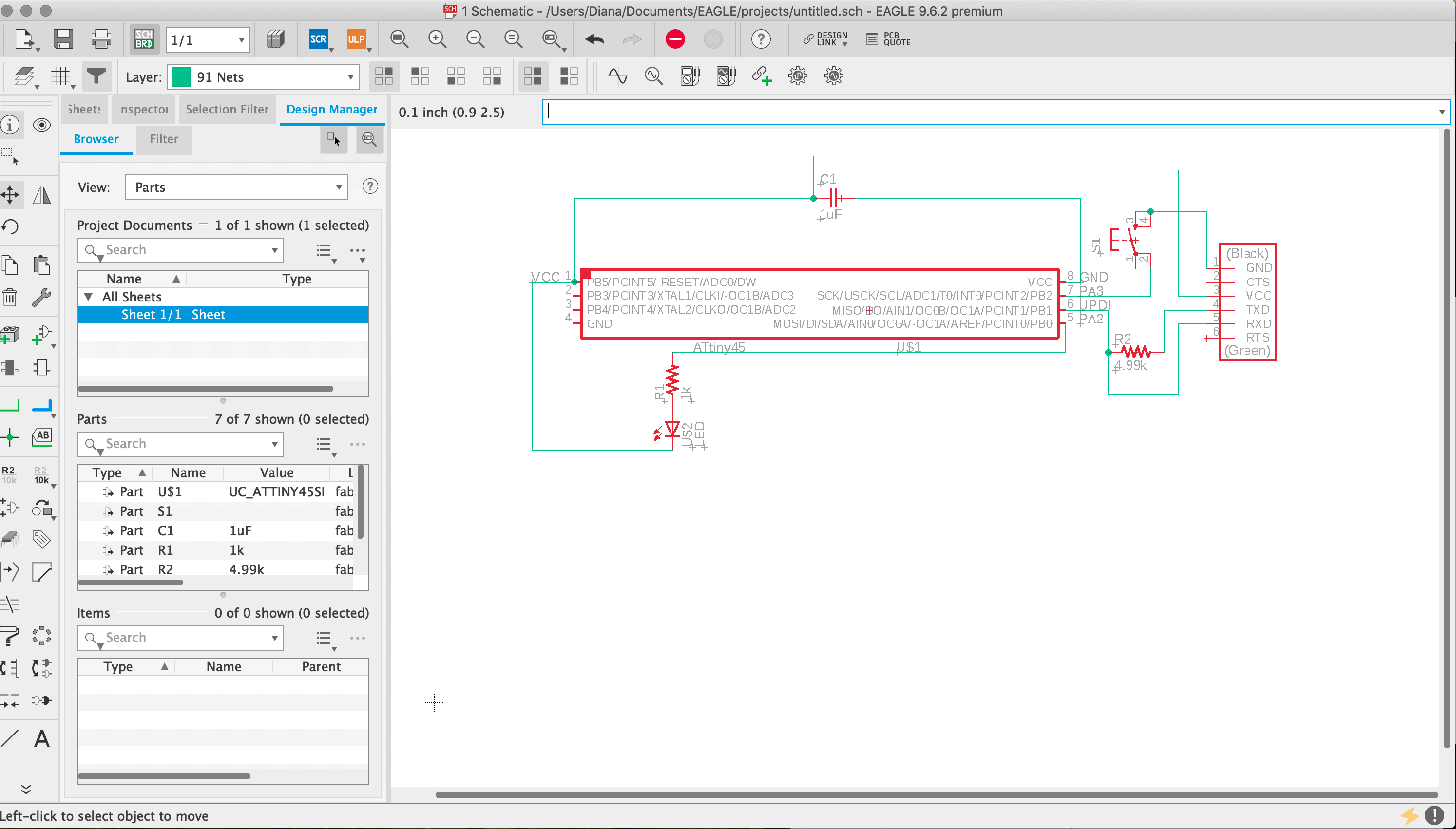
Eagle | Board Design:
Here is the board design layout in Eagle. My parts include: ATtiny412 microprocessor with 4.7k resister 1uF capacitor, LED with 1k resister, and a switch.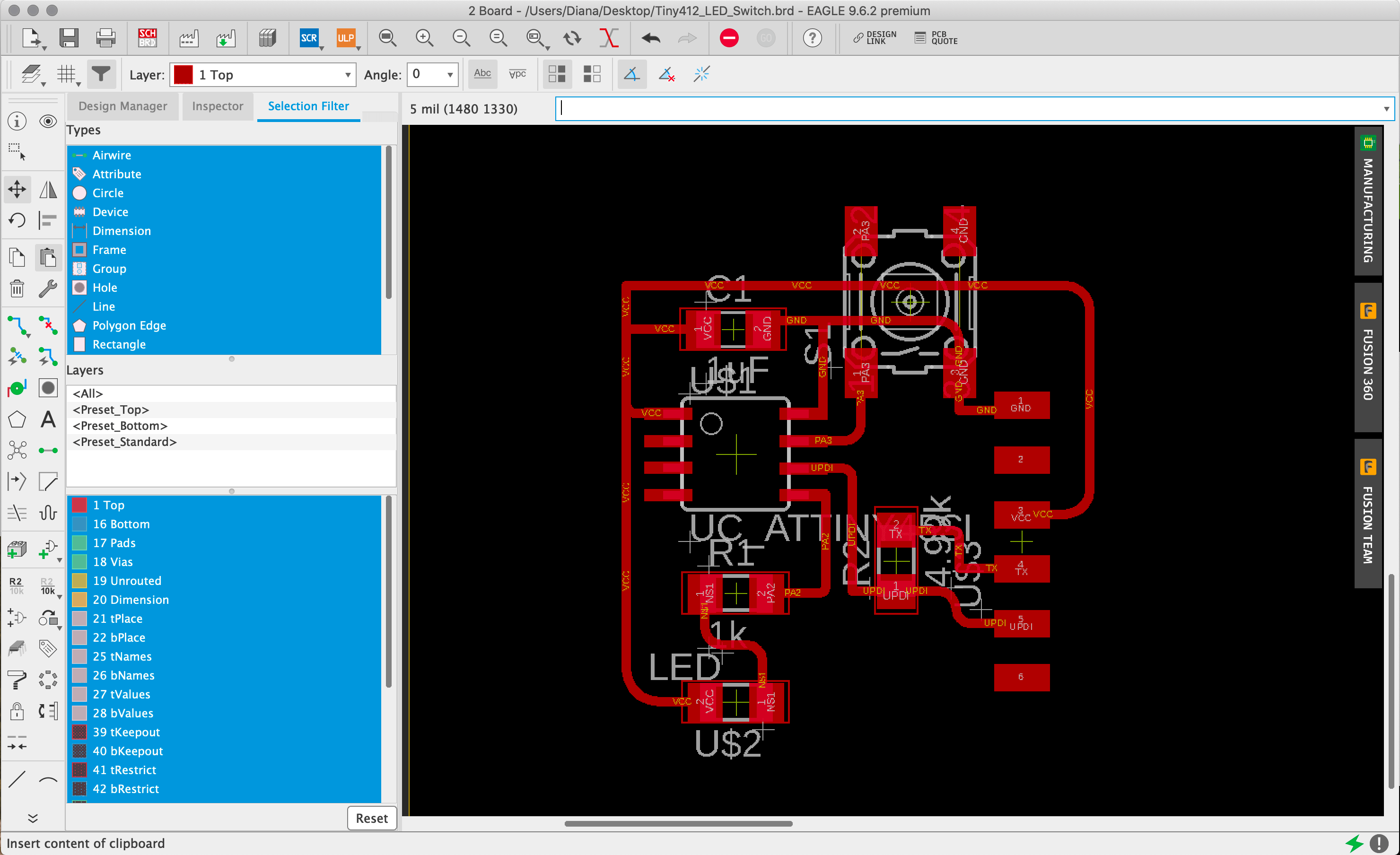
PCB | Board Design:
When exporting the board design .pngs for mods I first brought them into Illustrator to add some additional linework.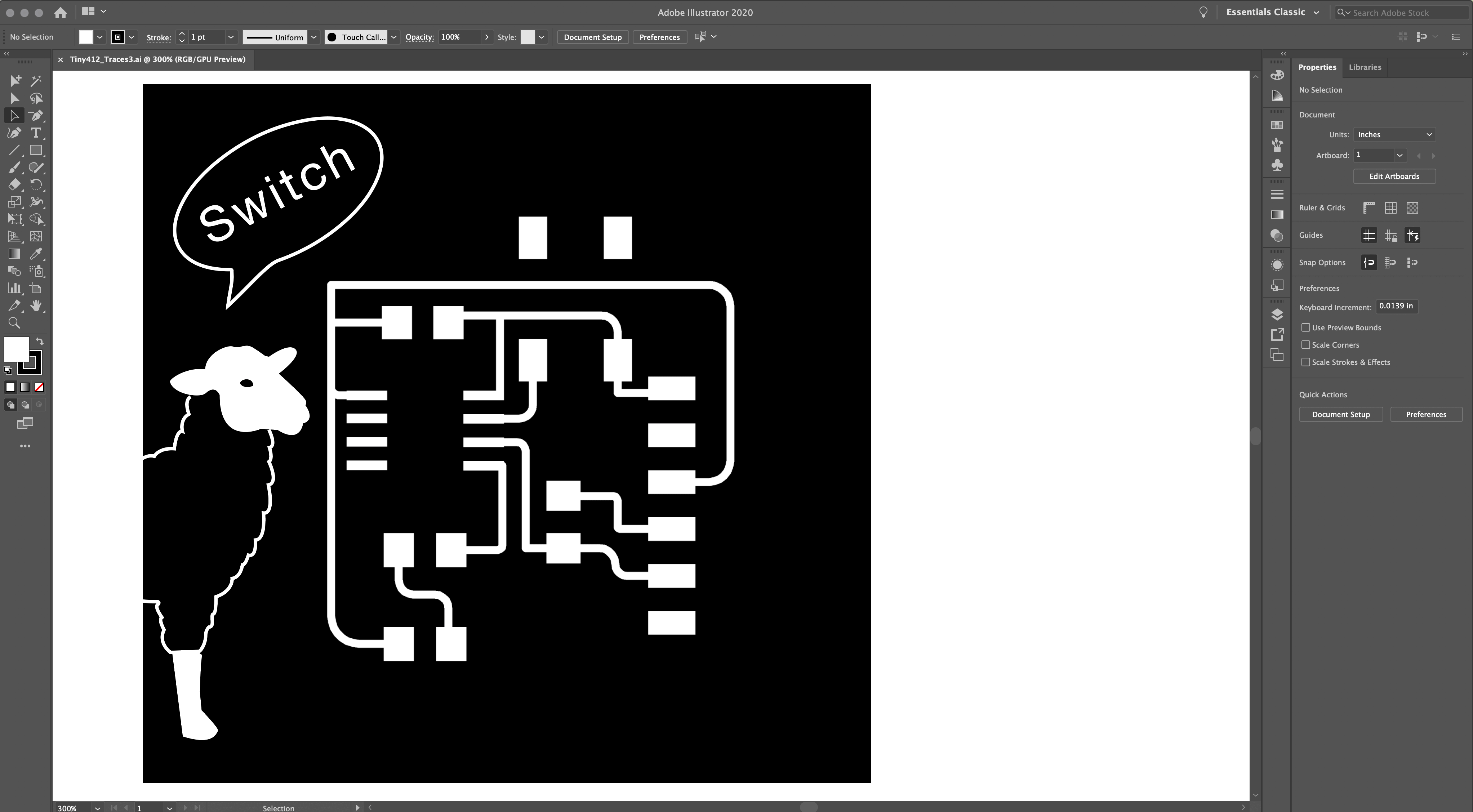
Mods | Board Design:
I offset the added linework in Illustrator to accommodate the tool path settings.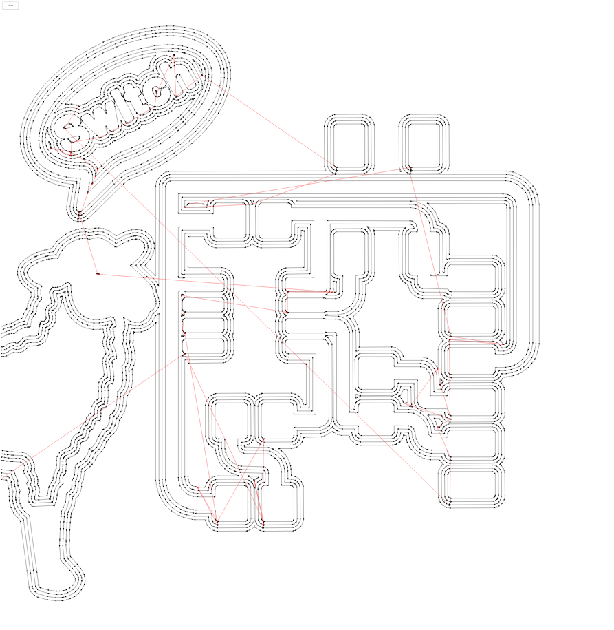
PCB | Milling:
After a few rounds on the Shopbot from the last few weeks this cut went well.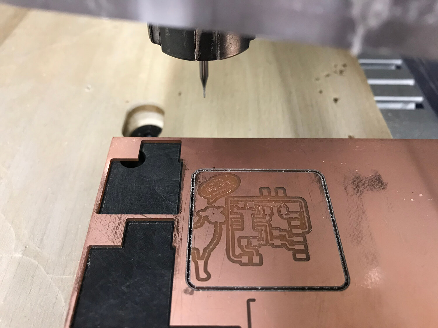
PCB | Stuffing:
An evolution of soldering from picking and placing parts, to tinning, to soldering.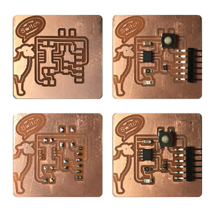
Arduino | Programmer:
Rob helped me out by putting together an Arduino UPDI programmer.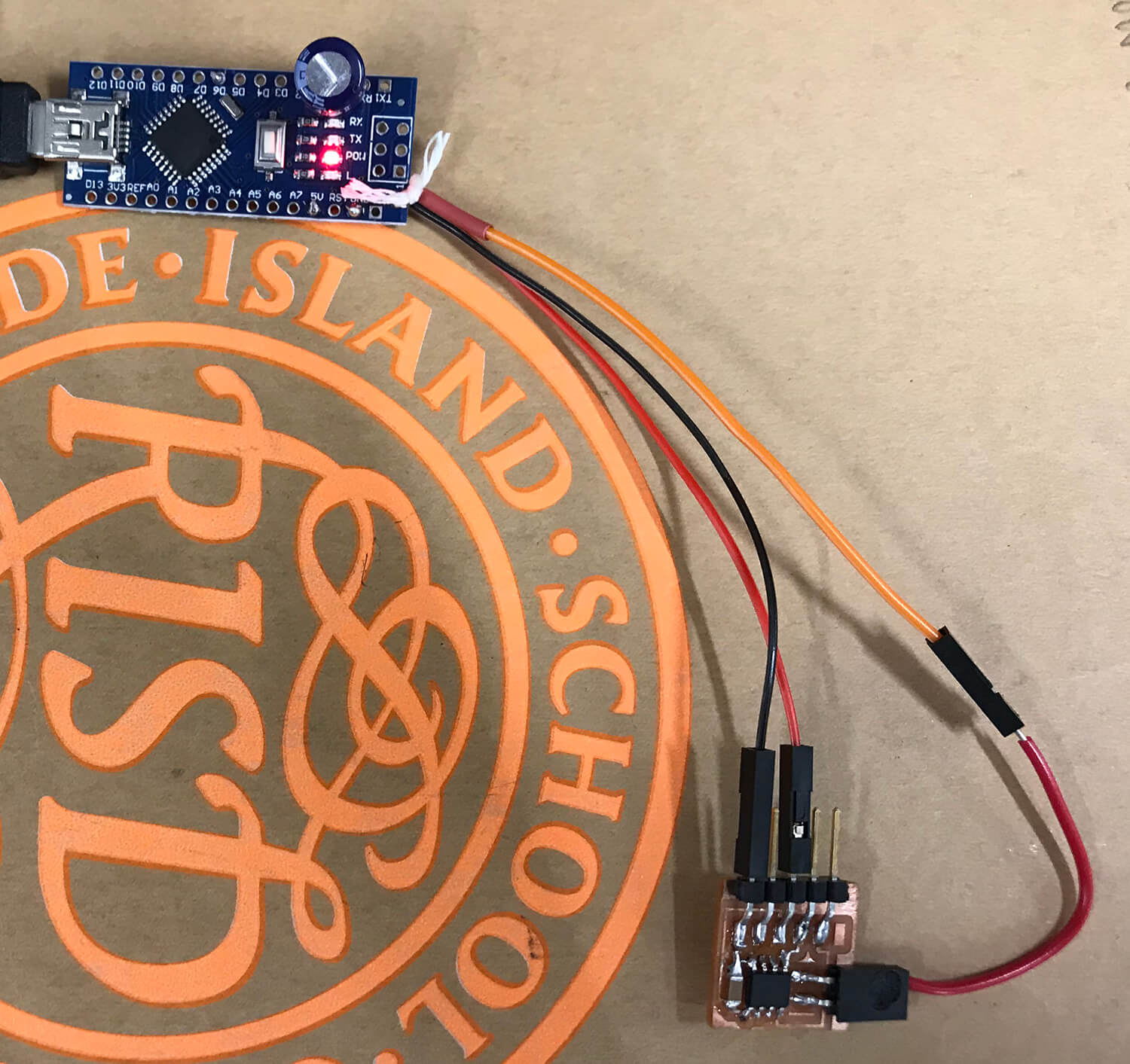
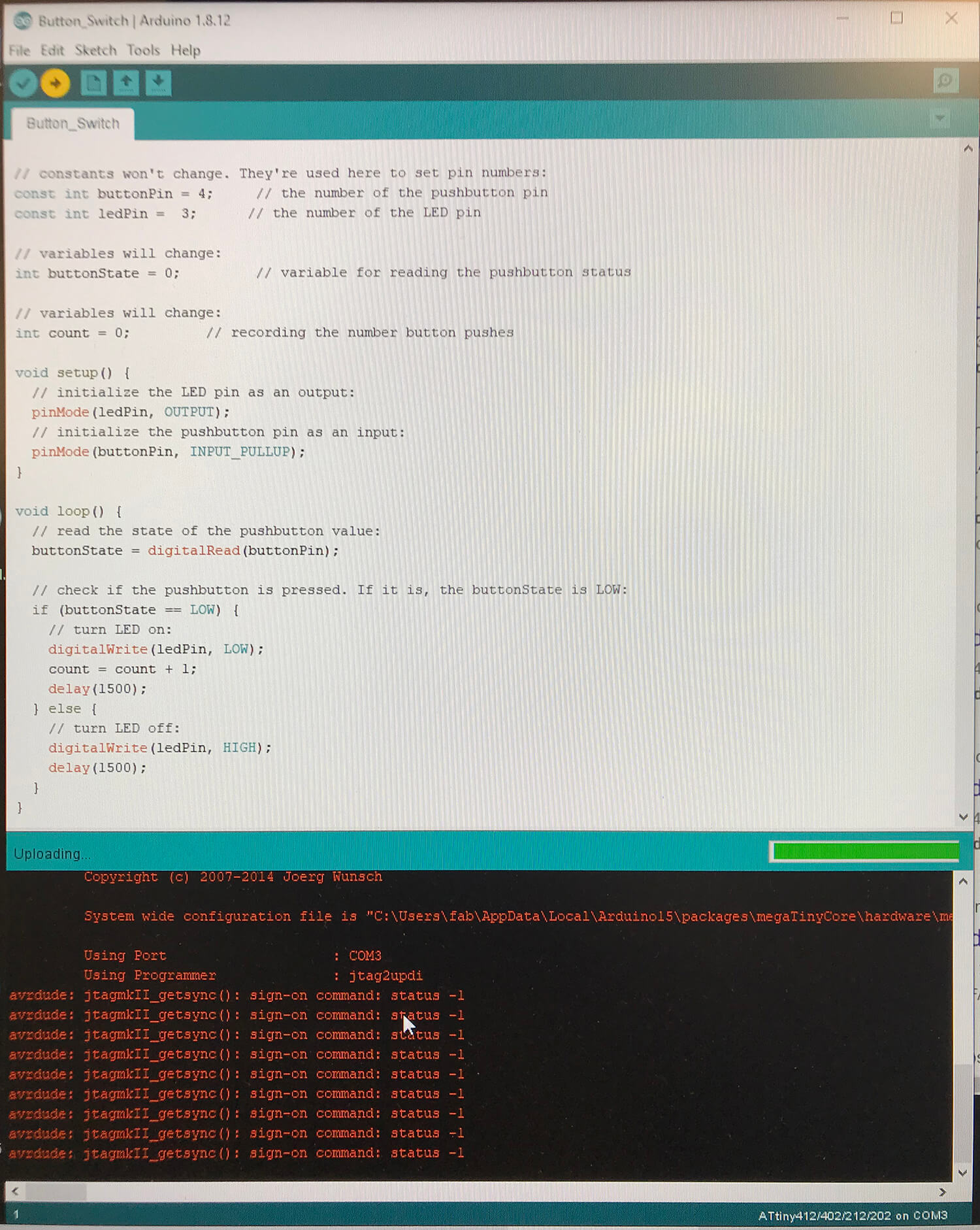
Arduino | Programming:
Using Arduino and working with Rob, I followed the site instructions for the ATtiny412 and compiled code for the button switch. After several attempts and several computers I gave up to move on to the next project in the interest of time!