Input Devices
Capacitive Touch Sensor:
In week six, I made a cube PCB around the SAMD11C chip that had capactive touch sensors milled in to the backside. I was able to program the board
and verify that the pads were indeed colecting step respones via Serial. I used those touches to control the blinking speed of some LEDs.
ESP32-CAM:
I used the ESP32-CAM module to play around with the development environment because the pins were essentially already broken out. I was able to get the camera streaming
demo working on my iPhone's personal hotspot and used the AI Thinker ESP32-CAM library on Arduino to do this. Following Neil's video
I also tried to flash the SPIRAM enabled Micropython environment but was not successful.
ESP32 WROOM Module:
The lab also stocked a bare ESP32 WROOM bare module, which is an awesome module that integrates Wi-Fi + BT + BLE on a MCU. If programmed by USB, it needs a USB-to-UART bridge chip and power circuitry.
FTDI makes a common chip, the FT232 for this purpose, but Neil has replaced the need for this by programming SAMD11's to serialize USB data.
Quentin wrote a great tutorial on how to set it up here. With that in mind, I tried to quickly design, mill, and assemble my board.
To hedge my bets, I ended up Amazon-ing a $12 FT232 USB module (cheaper one available here), which I will use in future projects.
Ended up being a wise decision.
Design, Fabrication, & Assembly:
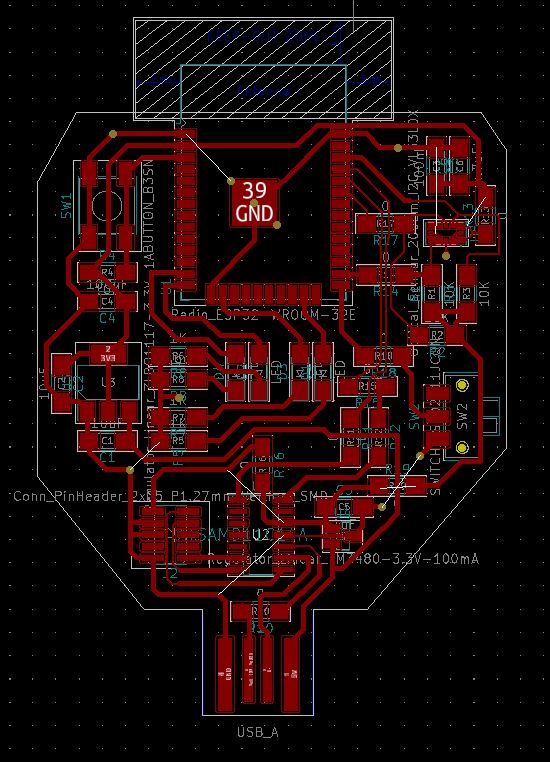
I designed a board for the ESP32-WROOM that included a USB-to-UART bridge on board. I also added a handful of LEDs, and the VL53L0X Laser TOF sensor, which can capture 1D range of and object within 2m.
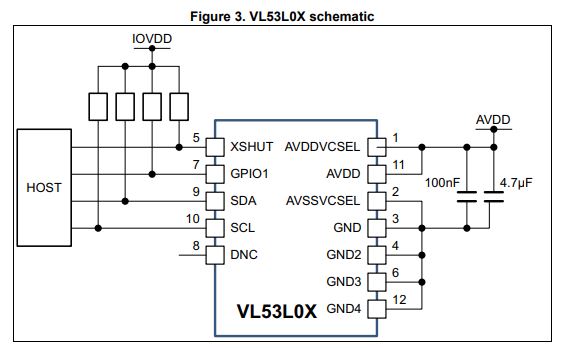
Because the LGA package, it is hard to solder on our milled PCBs, but I added it anyway as a bonus. Here's the minimum schematic from the datasheet that I used to wire it up.
Here are the schematic and layout of the final board:

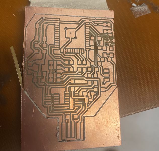
 When I started milling, there were no large copper boards left, so I used a scrap piece but found that it was already too bowed to be stuck on flat to the stage. All that was left was the 2x4" copper boards.
After fiddling with my layout for a bit, I was able to fit my components and routing and maintain safe spacing tolerances. I had to align the small copper board very precisely but ended up just squeezing my design in.
Gold star for not wasting material!
When I started milling, there were no large copper boards left, so I used a scrap piece but found that it was already too bowed to be stuck on flat to the stage. All that was left was the 2x4" copper boards.
After fiddling with my layout for a bit, I was able to fit my components and routing and maintain safe spacing tolerances. I had to align the small copper board very precisely but ended up just squeezing my design in.
Gold star for not wasting material!
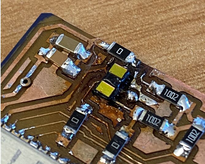
 Soldering the VL53L0X was a pain. I followed Zach's advice and tinned the pads, used lots of flux, and directed the hot air gun with the proper nozzle. I ended up melting a couple sensors before getting the solder to reflow.
On my third try, I put the entire mostly empty board on a 250C hotplate, waited 5 min, and tried again being careful not to blast one spot too long. It kind of worked.. I melted the package a bit again and made a huge bubble in the back copper,
but the component is solidly fixed on the board. I finished the assembly by using some nail polish to cover the entire ground plane on the backside.
Soldering the VL53L0X was a pain. I followed Zach's advice and tinned the pads, used lots of flux, and directed the hot air gun with the proper nozzle. I ended up melting a couple sensors before getting the solder to reflow.
On my third try, I put the entire mostly empty board on a 250C hotplate, waited 5 min, and tried again being careful not to blast one spot too long. It kind of worked.. I melted the package a bit again and made a huge bubble in the back copper,
but the component is solidly fixed on the board. I finished the assembly by using some nail polish to cover the entire ground plane on the backside.

Flashing & Bringup:
First, I tested the the SAMD11C USB-to-UART bridge by flashing it and ensuring that my computer recognized it as a serial device. I then tried to flash the SPIRAM binary but failed. The espressif idf tool recognizes the device
but doesn't start writing to the memory. Even after supressing the stub check and fiddling with the baud rates, the serial bridge does not write well. I spent some time in Microchip Studio trying to rebuild Quentin's project using
a lower baud rate but gave up after I couldn't replicate the setup environment. The error was at least indicative that everything was partially working including the ESP32 module.
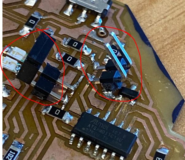
 I had a different idea instead, which was to cut the TX and RX traces, solder in headers, and use my trusty FT232 USB-to-UART bridge to program the ESP32.
 After trying again, it worked! I'll plan to return to the SAMD11C at some point because it would be a cool project and adds continuity to the materials discussed/used in this class.

Input:
Hall Effect: I used a speaker (same one I need for my final), which has a magnet in it to demo the hall effect sensor. It's not very sensitive but it works.
Wifi Scanning: Here I demonstrate the the ESP32 board I made is able to scan for Wifi networks.
Micropython: I was able to access the Python REPL after flashing the esp32spiram-idf3-20210202-v1.14.bin and still got a SPIRAM error. The newer releases did not work. Here I demo some basic python commands, however I hope to use this interface to communicate with the TOF sensor via an I2C bus. I opened the Python REPL via TeraTerm and will write a script in the subsequent section and upload it via rshell.
Laser TOF: To be added.. Hoping to connect TOF readings to web server interface.