Embedded Programming
Useless Cube v1.5:
Note:
This weeks update follows the same story arch of me planning some overly ambitious object to make, barely making it through its production, bodging boards, and coming up just short of executing my vision. I get a few new gray hairs wiser every week, so we'll see how the
rest of the semester turns out. Stay tuned.
Redesign and Layout:
I learned several weeks ago during the Electronics Design week that schematic design and layout were not too difficult.
Prone to human error, but low risk if you don't have many parts and maintain accurate design rules. It's the fabrication that takes longer. This week I simplified the back copper design, traded off vias for 0 Ohm resistors, and added better alignment marks.
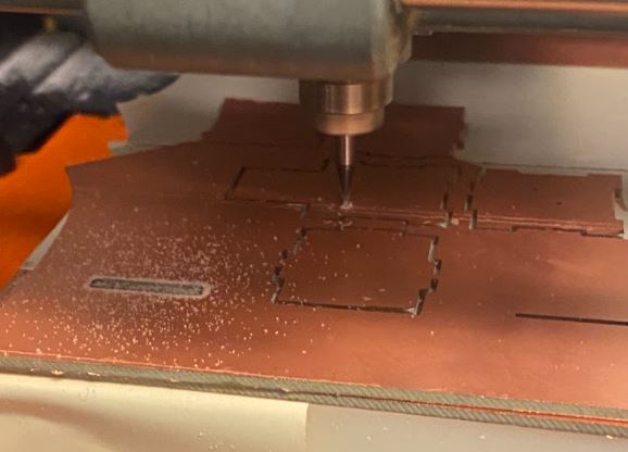
Fabrication:
To mill the board, a job that takes around an hour and 20 minutes start to finish, I found a time late at night to start. I chose the settings judiciously based on my experience from last time: change the cut depth to 0.006, changed the tool diameter to 0.014, and use the extra sticky tape.
The front copper and vias finished without issue. When trying to remove the board to mill the back, I found that the tape was too sticky to remove my pieces. I left small tabs in my outilne drill to make sure that the pieces maintained orientation
during the flip. Unfortunately I ended up snapping a few while prying the board (including the entire other half of the board). I found that a hammer and shim worked the best to preserve my board while smushing and shearing the tape without damaging the copper.
 To align the backside this time, I included a symmetric alignment mark in my outline file that punched a long slot through the pcb. I roughly aligned the endmill manually and iteratively ran the first 10s of the mill, which traced the alignment mark, until the mill was perfectly
outlining the mark with no overlap. I knew then that with the alignment tolerance designed in, the backside would mill fine -- and it did!
To align the backside this time, I included a symmetric alignment mark in my outline file that punched a long slot through the pcb. I roughly aligned the endmill manually and iteratively ran the first 10s of the mill, which traced the alignment mark, until the mill was perfectly
outlining the mark with no overlap. I knew then that with the alignment tolerance designed in, the backside would mill fine -- and it did!
Assembly, Debugging, Bootloading:
Assembly went smoothly until I plugged the board in. After watching in horror as Neil displayed a giant, poorly-sized image on my website of my terrible soldering job a couple weeks ago, I was determined to solder a nice board.
It looked good after the first pass, but after plugging it in and debugging, I found some traces that had shorted VDD to GND. Because I had soldered the board together so quickly and trusted my milling, I was not careful about checking some pads. I even found a short from a tiny piece of
stray copper from milling. Most debugging is fairly deterministic. You follow a trace, check continuities, and measure voltages when powered based on expected behavior of discretes. Most of the time, you find a mistake. The microcontroller, however,
is a black box. There's always a lingering suspicion that it's borked because you think you've found all the bugs. I spent a couple grueling hours in this hell and ended up ripping up and replacing my initial microcontroller just to find a different fatal bug. My mf LEDs were flipped!
I eventually flashed the bootloader for the SAMD11C successfully with the Atmel ICE and Microchip Studio and began programming, which was the actual assignment.

Programming: Arduino code was very simple and only takes a few lines to test the functionality. I first went through the peripherals and verified they were all working. LED blinks:
 Weird that blue LED doesn't get very bright even though I chose a 499 Ohm to draw 4-5mA through..
Button Press:
Capacitive Touch Sensor:
Putting it all together:
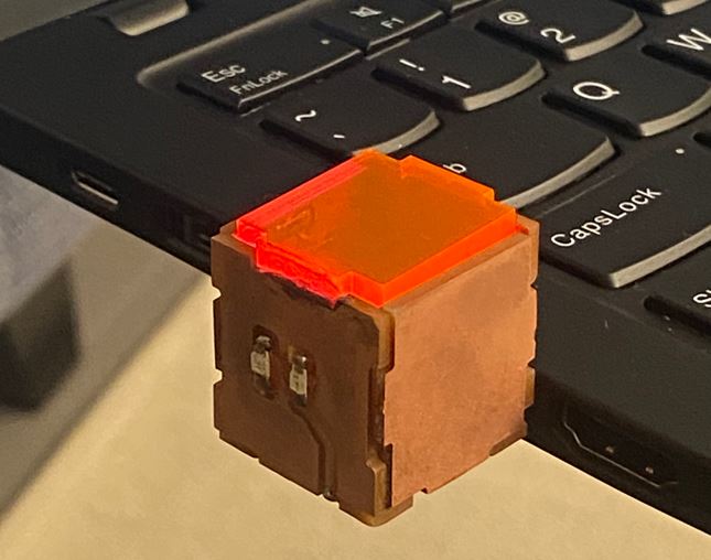
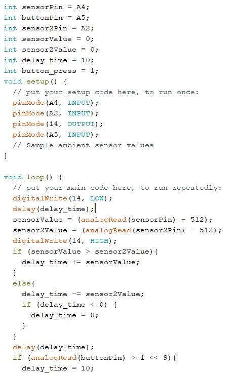 Here's the simple script which accelerates the blinking if the top touch sensor is touched and decelerates if it bottom sensor is touched. The button on the cube's bottom side resets the flashing back to default.
Because the touch sensors are analog sensors, it's harder to reliably attribute presses to touching them. I intentionally chose large resistor values so that when touched (and putting the body's capacitance in parallel with ground),
the time delay of the decaying voltage would be several ms, which is enough for the microcontroller to sample a value that stays more stable. We get a 10-bit number from the analog sensors, which was easily thresholded to determine when it was pressed.
Here's the simple script which accelerates the blinking if the top touch sensor is touched and decelerates if it bottom sensor is touched. The button on the cube's bottom side resets the flashing back to default.
Because the touch sensors are analog sensors, it's harder to reliably attribute presses to touching them. I intentionally chose large resistor values so that when touched (and putting the body's capacitance in parallel with ground),
the time delay of the decaying voltage would be several ms, which is enough for the microcontroller to sample a value that stays more stable. We get a 10-bit number from the analog sensors, which was easily thresholded to determine when it was pressed.
 Unfortunately, I think my microcontroller is borked. After around 10 flashes through Arduino, my laptop won't recognize the device when it's plugged into USB and I can only flash code via the programmer. One day I will try to replace the microcontroller but not today.
I also tried bare-metal programming through Microchip Studio and used the proper ASF configuration to echo through serial. This is the much better alternative to I never got a video of the final working script, but at least the cube looks nice. Onto the next.
Unfortunately, I think my microcontroller is borked. After around 10 flashes through Arduino, my laptop won't recognize the device when it's plugged into USB and I can only flash code via the programmer. One day I will try to replace the microcontroller but not today.
I also tried bare-metal programming through Microchip Studio and used the proper ASF configuration to echo through serial. This is the much better alternative to I never got a video of the final working script, but at least the cube looks nice. Onto the next.