Idea: Aeroponic System
Goal: Build an aeroponic system that can be extended to experiment with salt concentrations to test out viability of offshore aeroponic plants.
Background
Farming takes up a large swath of livable land around the world and as populations increase and demands for food follow suit, new and interesting ways of tackling space issues must be implemented. We have already seen vertical farms utilizing hydroponics and aeroponics to increase the output per square foot of land used while minimizing water used by about 95 percent. However, I am interested (in the long run) of figuring out ways to save even more land area and even more water. My initial idea is around the concept that some plants such as spinach can live in somewhat salinated environments while allows the possibility of having vertical farms offshore that dilute seawater to an acceptable level and grow leafy greens. However, after beginning the project and realizing how much time I have to complete the project, I decided to scope things back and start off with a simpler aeroponic project first. The goal of this project for the semester was to build a modular aeroponic system that I could keep in my room and later modify to experiment with different concentrations of salt in the water. To store it in my room I planned on building the general structure using the fabrication skills gained in this class and the water and light system using the electronics skills I developed throughout the semester. I opted to try and make it modular for a couple reasons. First, I wanted to be able to scale it up and down to house however many plants I want in case the size of my living quarters changes, which it will undoubtably do over the next few years as I move away from MIT into the real world. Second, from what I have seen online, there are not any modular aeroponic towers with grow light attachments for small sale consumer use which I think is a shame.
Here are some links to some literature about salinity with plants which was the initial motivation for exploring aeroponics: Irrigation, Seawater Farming, and Tomatos
TLDR and Parts List
I built a modular aeroponic system using these parts:
- 3x 12 in. x 24 in. x 3/16 in. Clear Acrylic: $45 at Altec Plastics
- 1x 12 in. x 24 in. x 1/8 in. Clear Acrylic: $10.15 at Altec Plastics
- 1x 12 in. x 24 in. x 1/4 in. Clear Acrylic: $18 at Altec Plastics
- 2x Ultrasonic Atomizer 3.7-12V: $14 at Amazon
- 1x SAMD11C14A Microcontroller: $1.62 at Digikey
- 2x N-Channel MOSFET: $2.28 at Digikey
- 1x 3.3V Voltage Regulator: $1.53 at Digikey
- 12x Bright White LEDs: $1.55 at Digikey
- 4x Deep Red LEDs: $2.44 at Digikey
The Initial Design
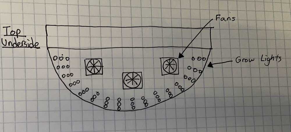
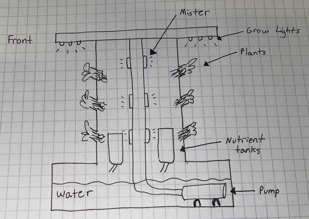
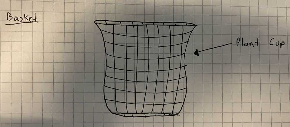
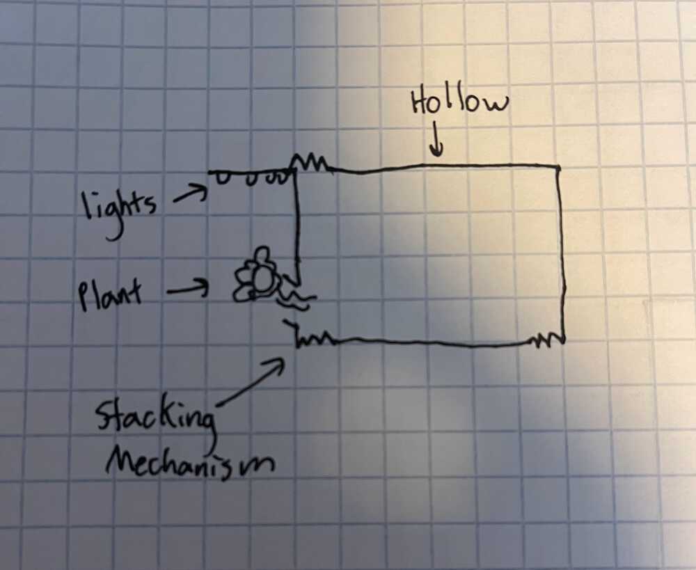
The initial design of this was similar to some existing commercial aeroponic towers, but incorporated built in grow lights, fans, water control, and modularity. This will (hopefully) allow me to grow stuff even in the height of Boston winter. Below you can see some sketches of my design's top view, front view, and underside view, as well as a sketch of the basic idea for the baskets which will hold the plants.
More Designs
The Initial Light System
For the system of lights I have two different ideas. First, having one main centralized source of light coming from the top panel as shown in the previous drawings. Second, having a more modular approach where each plant holster has its own grow lights that can be connected in a wired network to a control board. For sake of scalability and novelty, I will focus on experimenting with the modular approach.
Preliminary CAD
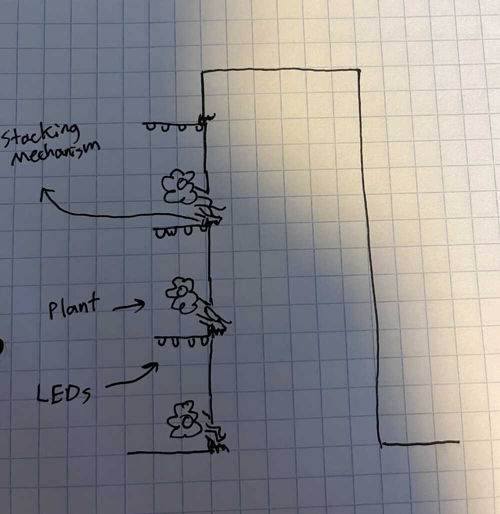
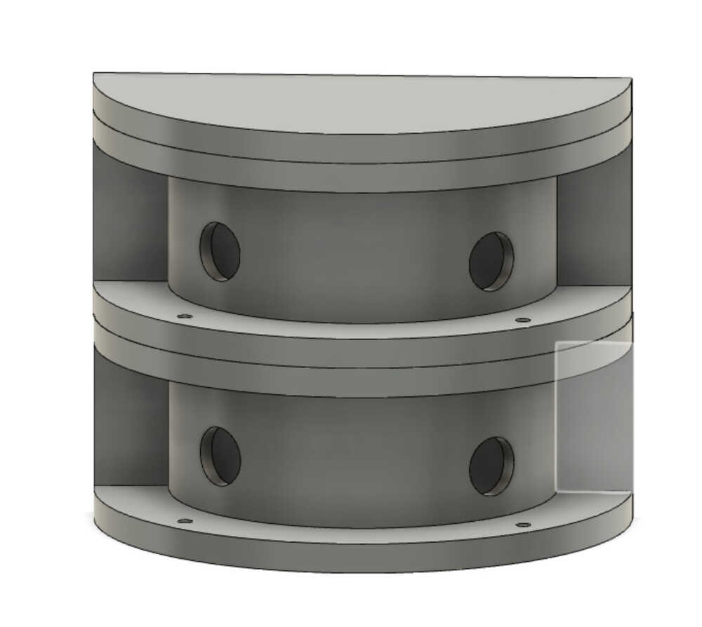
Here is a preliminary CAD of a modular design that incorporates a way to stack pieces together and connect lights hanging from each overhang into a circuit by attaching the light boards above the cutouts for the plants. In the CAD below you can see two modules stacked on top of eachother with a lid on top. This represents the outer structure of the tower.
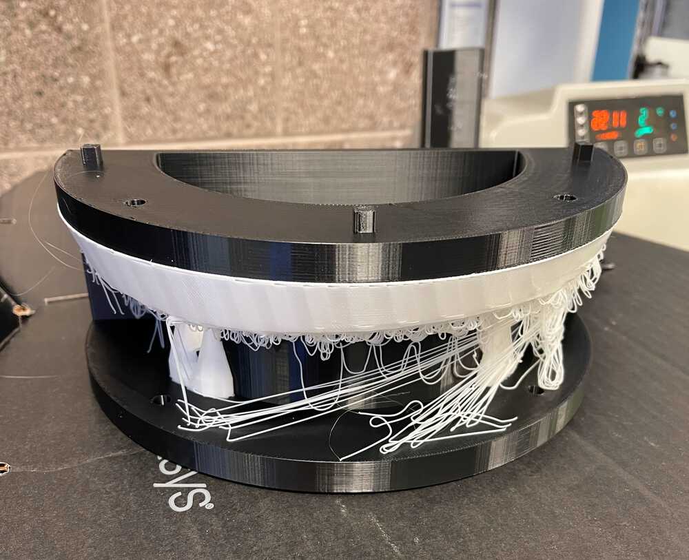
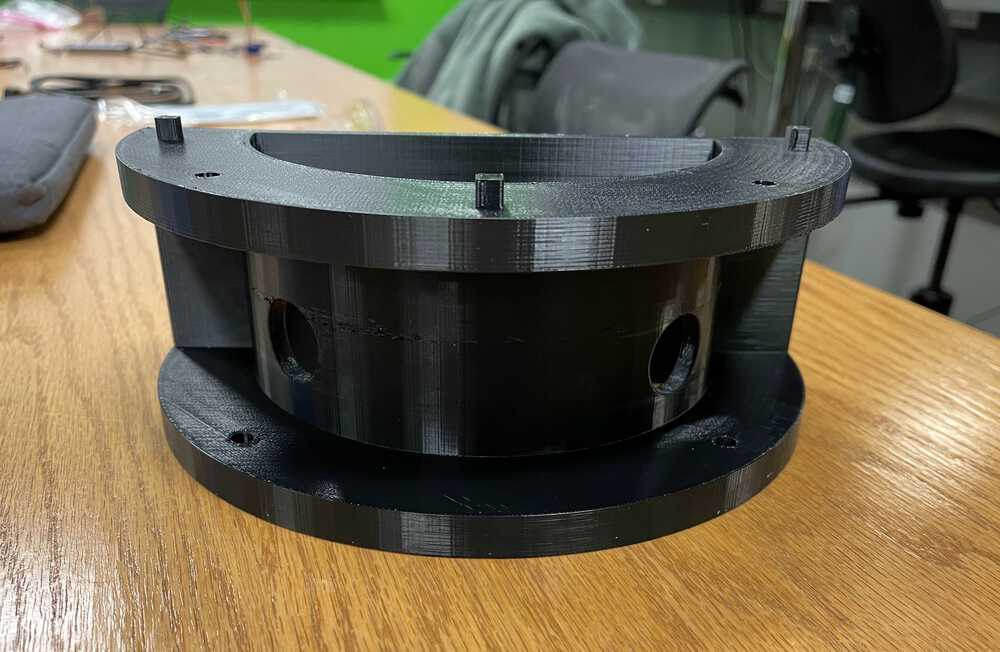
In order to test this design out and use it as a base for testing the other systems involved in the build, I decided to try out the large Stratasys printer we recently got in EDS by printing one of the modules. Even though the printer bed was large and I was able to make a substantially sized part, I still think I might explore other options for the final build. Right no I am leaning towards some sort of acrylic so I can heat it up and bend it into a nice curved shape, or redesign my tower to be less curvy and then just super glue laser cut pieces together. Below you can see the vision I had for stacking them together as well as the print.
Reflections
After playing around a bit with the print and some lights (see later sections on the creation of these) I decided I wanted something larger. While the 3D printer was a nice way to additively build out the pieces and would have made manufacturing modules much simpler, the size was a constraint I wasn't willing to live with so I decided I would instead laser cut and construct the modules using acrylic, super glue, and some sort of water proofing mechanism.
Design Round 2
Although I was sad to leave behind the curves which were made easy by additive manufacturing techniques, I opted for a very similar design utilizing the the laser cutter. I kept key pieces such as the circular cutout for the plants, the mounting holes for the grow light system, and the general shape. I added in different slotting mechanisms to connect which I plan to coat with copper tape to allow each module to work together in a single parallel circuit. I also added in wire holes for the water component which I plan to mount to the back of the structure. In the CAD you can see 3 main components: the lid which will consist of an acrylic sheet with glued in notches to allow it to sit slide into the top nicely, the main plant module which has the overhangs for the lights as well as cutouts for the plants, and the base which will be water proofed and acts as the water and nutrient reservoir.
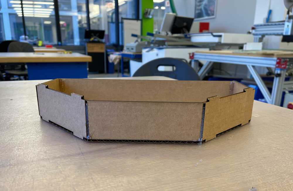
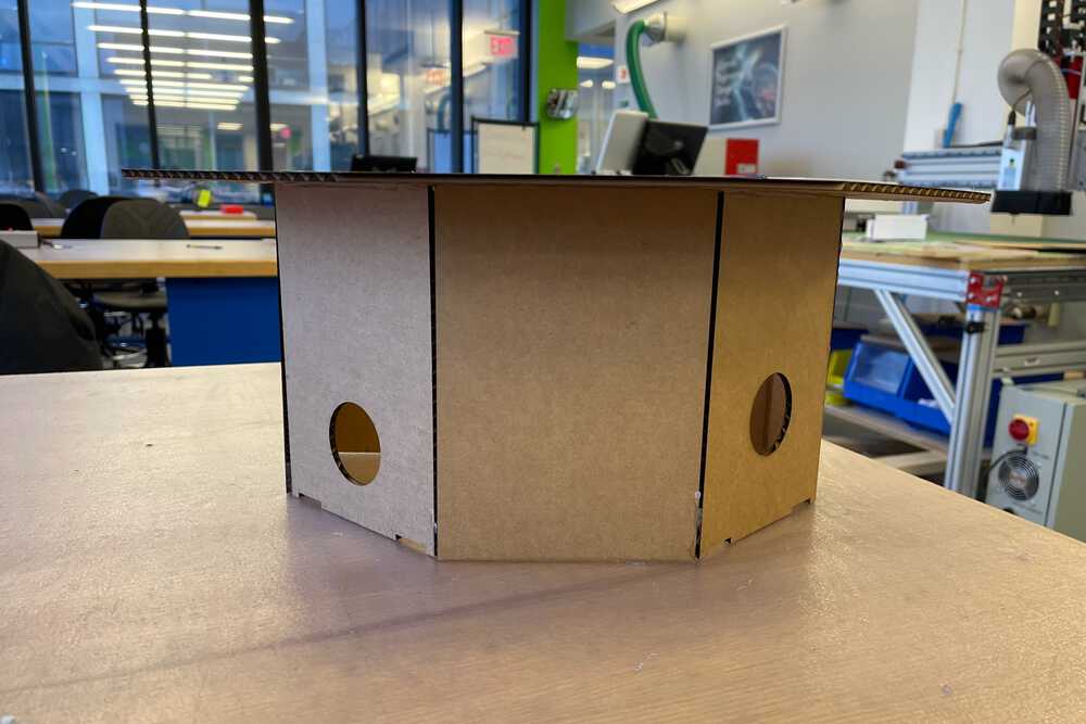
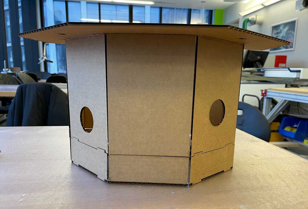
Cardboard Tests
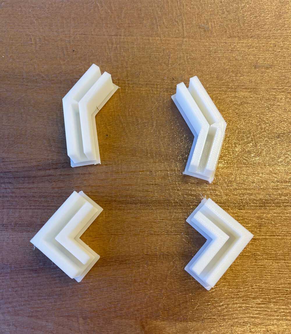
Before cutting out on the acrylic I bought, I first started with a cardboard test which I cut out using the Epilog laser in EDS. I then tested out the feasibility of glueing everything together by using hot glue, although I plan on using super glue and some sort of caulking for the final build. Putting things together, I noticed a few things got messed up when I changed my parameters in Fusion 360 so I went back and fixed those, but otherwise, I was generally happy with my design besides the slight difficutly in holding the pieces at the correct angle while glueing. To get around this, I designed some simple connectors to hold the pieces at the desired angle (135 degrees and 90 degrees) and 3D printed them on the Sindohs we have in our lab. Finally, I did some acrylic clearance tests so I could change the parameters in my CAD to allow for a nice press fit on my connectors. I ended up opting for 1 inch width female joints and 1.02 inch male joints as this gave them a nice fit, but was still easy enough to take apart the modules and rearrange them. At the end of the day, these joints acted mainly as a way to line up the levels of the modules and prevent them from sliding off.
Final Build
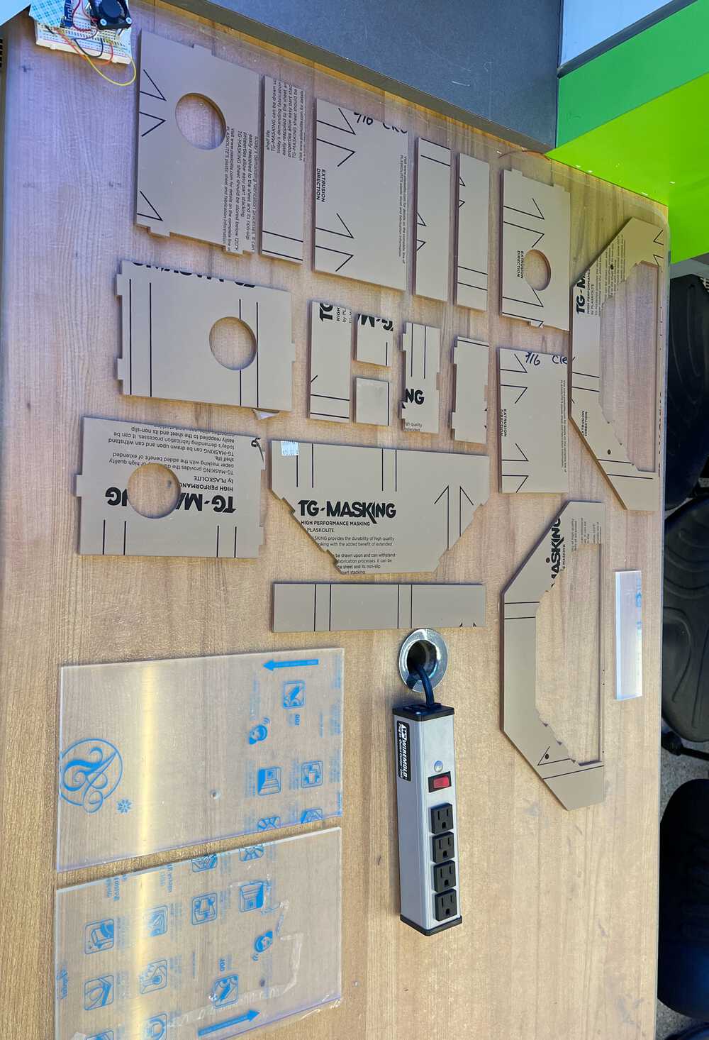
Finally, the moment has come to start the final structural build with the clear acrylic I bought. I ended up purchasing 3x 12 in. by 24 in. by 3/16 in. clear acrylic sheets and 1x 12 in. by 24 in. by 1/8 in. clear acrylic sheet, but ended up having to use one of the sheets in EDS which was 12 in. by 24 in. by 1/4 in. This led to some slight changes to the design on on piece, but luckily I used parameters so it ended up not being a problem! To get the sheets laid out nicely with all the parts I followed these instructions that previous me wrote (thanks!) and exported the parts as a DXF then used the file to laser cut. Our laser is getting a little bit old, however, so I ended up having to go over the pieces twice, once with slow speed at 100% power and once with a faster speed to cut the rest of the way through. You can see some examples of each below.
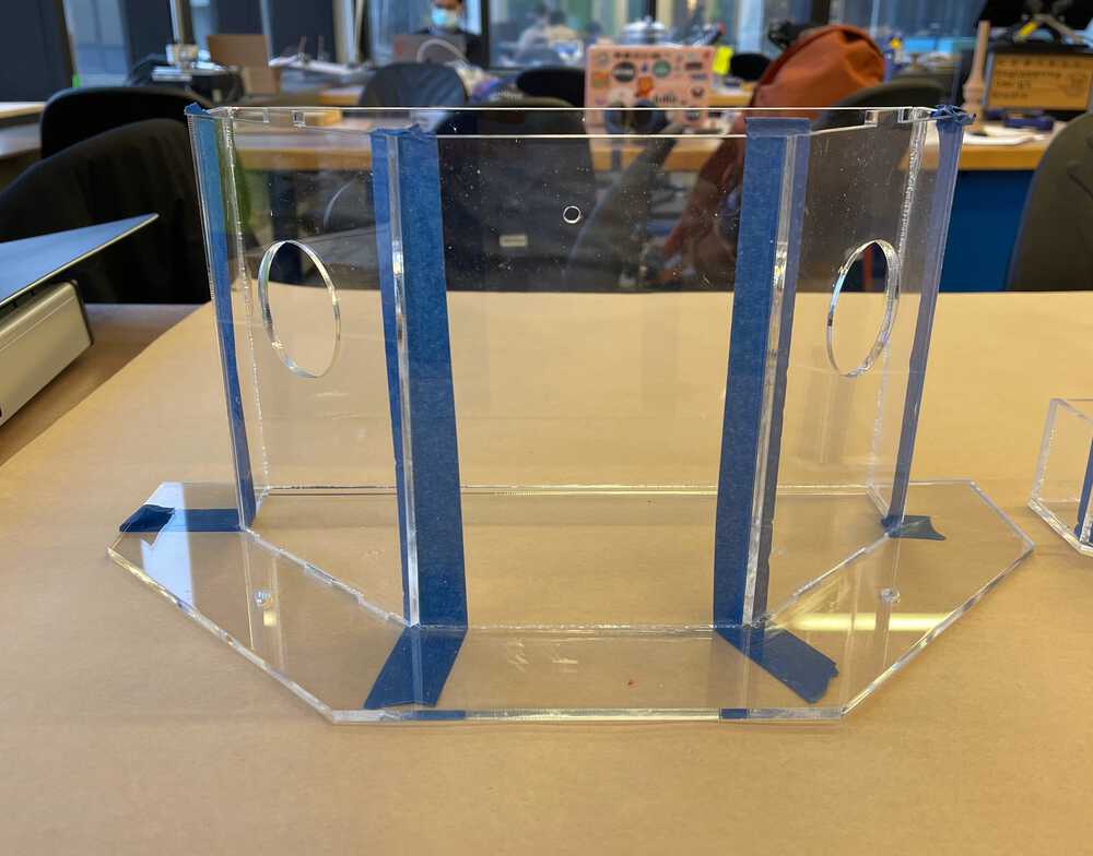
After all 5 sheets of acrylic were cut, I laid out all the pieces and removed the protective coatings on each one, then got to glueing! Pictured below you can see an example of how I used my 3D printed connectors to hold the pieces a the correct angle while I super glued them together.
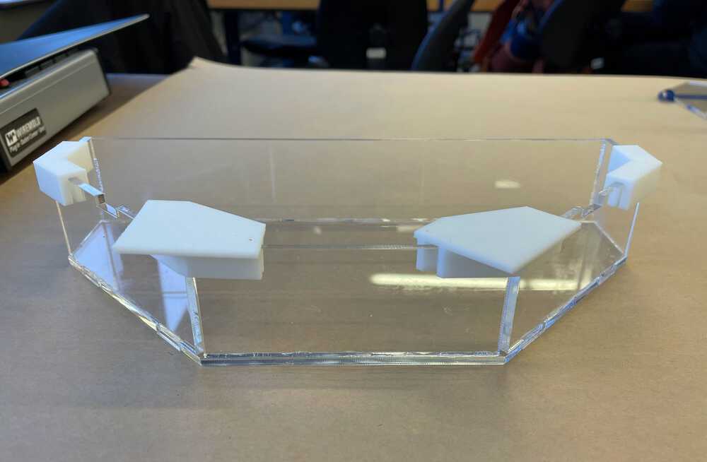
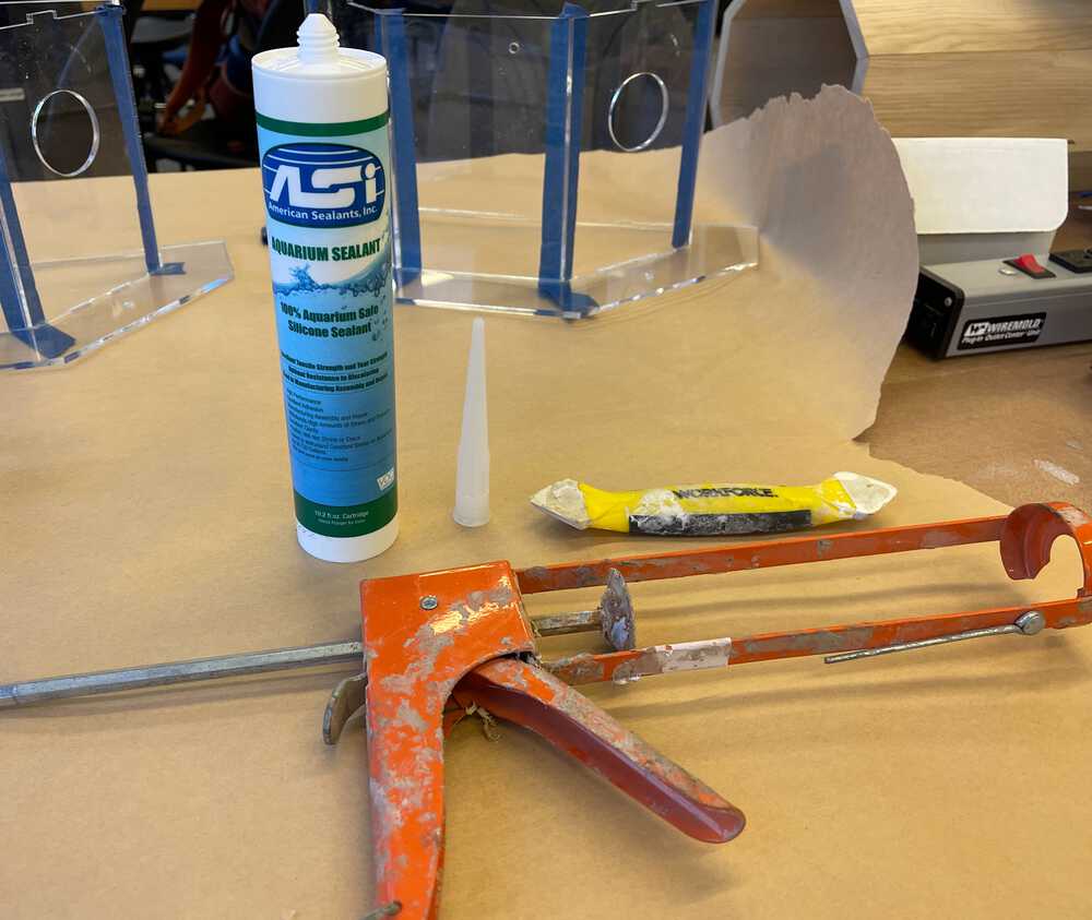
The next step in the build was to waterproof everything. I ended up ordering some aquarium sealant to make sure that no harsh chemicals would leak into the water and kill my plants. This was my first time every using any sort of caulk/sealant so kudos to Dave for loaning me his caulk gun and scraping tool which made this job so much easier. The sealant also helped to function as a strenghting device since the super glue actually was not that stable for the large side pieces of the module. In order to hold things together nicely and allow me to caulk all the way up the sides, I put masking tape along the corners then got to work sealing all the seams between pieces. In my CAD I made sure to leave space for the sealant to fit into in order to prevent excess clumping along the outside of the structure. At this point is where the scraping tool came in very handy as it allowed me to sort of push the sealant into the crevices and remove any of the excess. Once again, thank you Dave, you are a life saver.
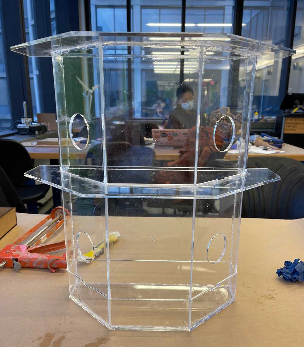
After caulking everything I let the pieces sit for 24 hours to fully set, before testing the base to ensure it was waterproof and putting the whole assembly together.
Lighting
After scouring many websites and articles for info on optimal lighting ratios between the different wavelengths of light for horticulture, I discovered there are many different approaches to achieving "optimal" growth. Some sites recommend a combination of red and blue leds varying in ratio between 3:1 and 9:1 while others recommend a 4:1 ratio of white to high red. After digging in to more research I discovered that the science is somewhat non-conclusive here and depends heavily on plant type and other factors so I opted to go with roughly a 3:1 ratio of white light to red light as this will encompass the whole spectrum of light necessary for the various stages of plant growth while focusing on red which is generally considered the most important for encouraging photosynthesis. Below I have listed the different wavelengths and their importances.
- Blue Light: (430-450 nm): Encourage vegetative growth.
- Red Light: (640-680 nm): Encourage stem growth, flowering, fruit production, and chlorophyll production.
- Green/Yellow Light: Mostly reflected to give leaves their green color, but some is absorved for use in photosynthesis
Luminosity Calculations
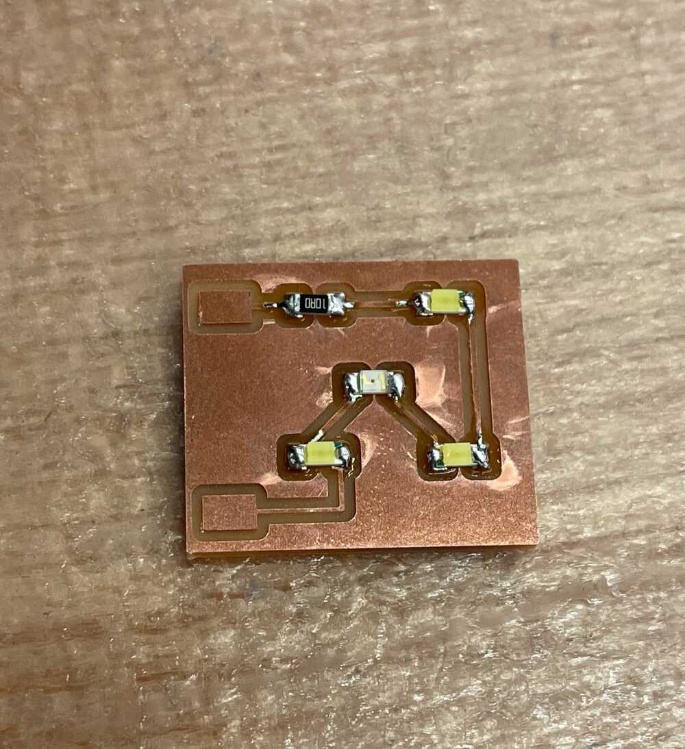
Most full sun plants require roughly 2000-3000 lumens per square foot of growing space in order to grow well so I will be using this number to fuel my calculations on the number of leds needed for each plant section. To start my calculation I found an example of a white led on digikey in order to ascertain their lumen outputs (link). From here I saw the led outputs 179 lm / W with a voltage of 2.8V and a current of 350 mA. Since W = V*A we get W = .98. Plugging this in to get lumens we get 187 lm / W * .171 W = 31.977 lm. From here we can assume the grow area will be about .2 sq. ft. (this is just an estimate). Dividing 31.997 lm by .2 feet squared we get about 159.885 lm/ft squared. We must also take into account lumen drop off over the distance using the formula B = L/(4piD^2) where B is the brightness in lumens per unit distance, L is luminosity, and D is the distance to the source. Plugging in our numbers we get 159.885/(4pi(.125)^2) assumming we are around 1.5 inches from the source. This gives 814 lm/ft^2. Finally, if we want about 2500 lumens per square foot we divide 2500/814 to get ~ 3 leds needed to provide sufficient light.
For the red led I used this light and put it in a series circuit with the white leds. These ones are 2.25V and take a max current of 150 mA, however, so I was constrained by the white LEDs when picking what current to run the circuit at since they were supposed to be run at 60 mA. To figure out what resistance to add to my circuit I used V = IR where V = 12V - (sum of led voltages) to get 12V - 3*2.85V - 2.25V = .06 * R. Solving for R I got that I needed a resistance of ~20 Ohms. I decided to be a little bit safe and went ahead and put a 27 Ohm resistor down since I was scared the resistors might heat up and thus have decreased resistance over the many hours the system would be on.
PCB Design
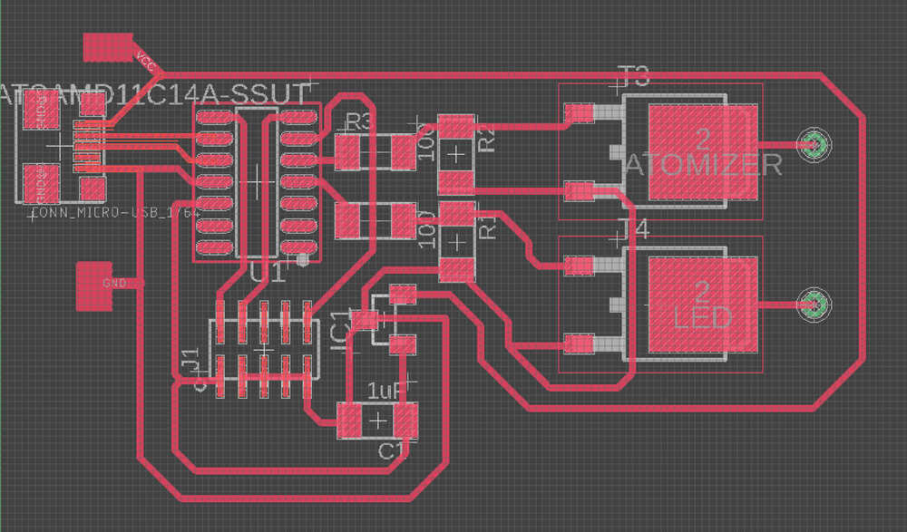
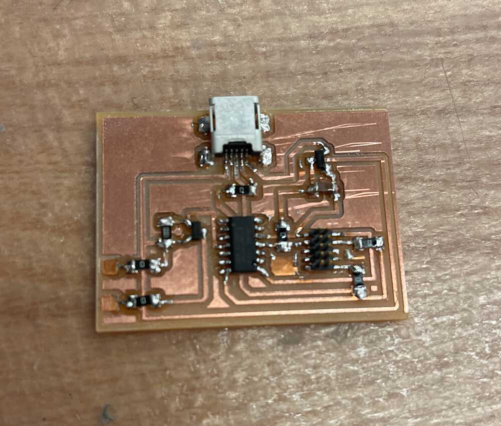
I went over a similar board in my Week 10 write up here, but decided on milling a new board this week to allow for control of both the lighting system as well as the water system which I will talk a little about later. The board consisted of a SAMD11C microcontroller, two N-channel MOSFETs to control the light and water circuits, a micro-usb port to program the microcontroller with, and wires for power and ground to connect to a 12V power source which gets level shifted down to 3.3v to power of the microcontroller. Below are some images of the board.
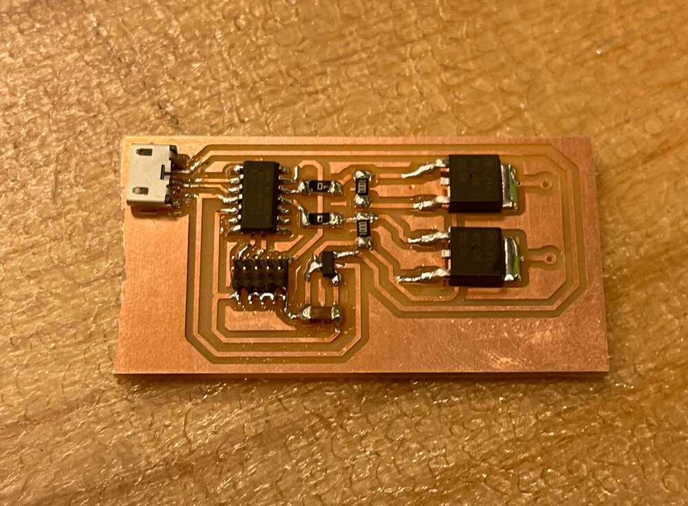
Milled and Stuffed PCB
Here are the stuffed PCBs.
Programming
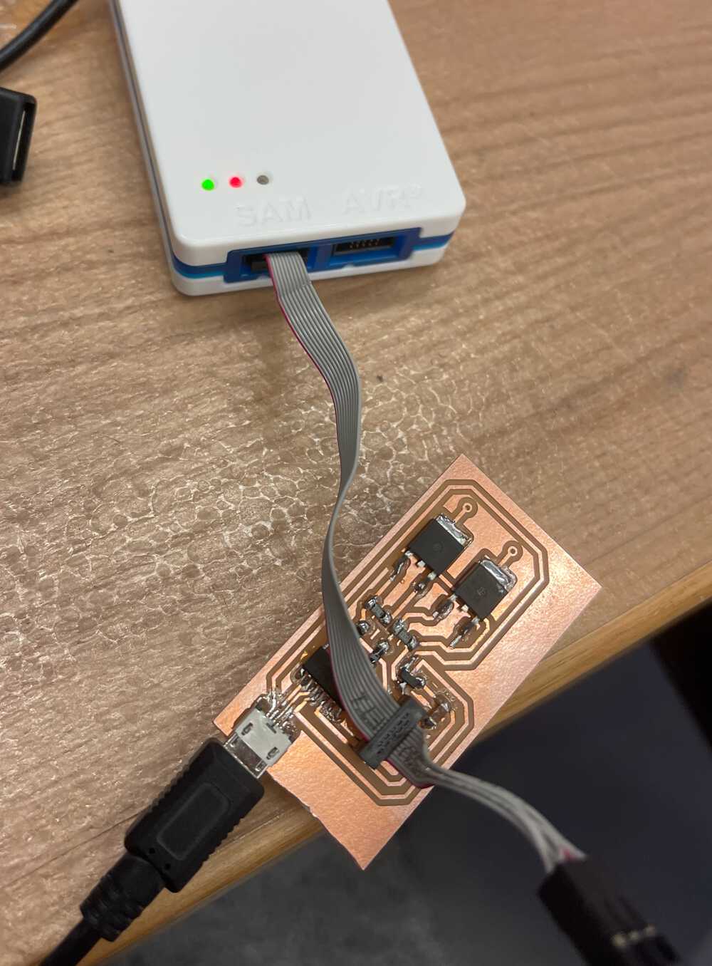
To program the board, I first bootloaded the microcontroller with an Atmel Ice, then I was able to load code through the Arduino IDE onto the device using the micro-usb port on the pcb. The code for this project is relatively simple and required me to just have timers in a loop to handle turning on and off the water system and lights based off what is specifically required of the plants I am growing. For sake of the demo, I ended up just leaving them always on, but you can see in the code below that I have it on a short timer for each to show how it would work. You can see this code working above on the 3D printed test I did earlier.

Water System
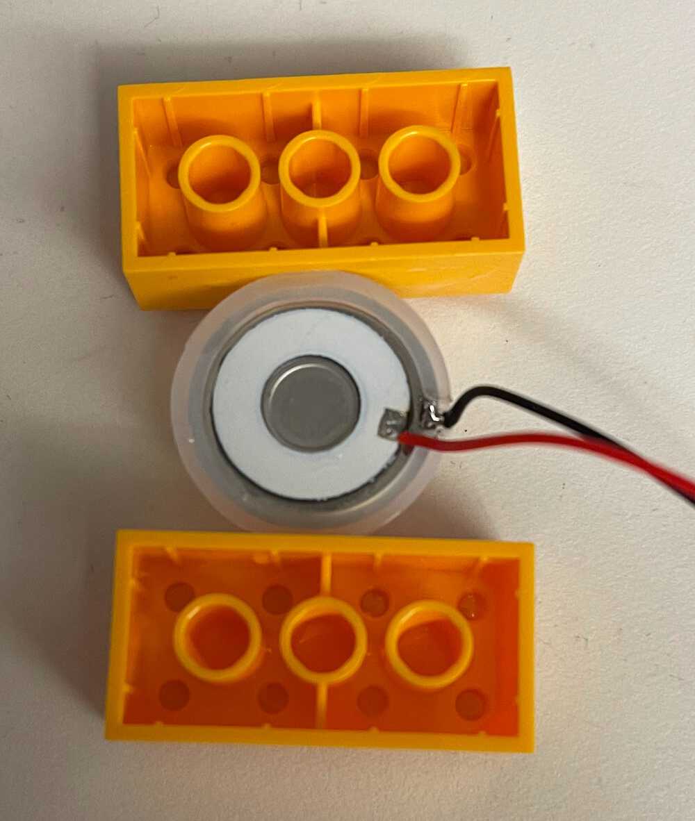
After researching high-pressure and low-pressure aeroponic systems and looking at the feasibility of creating my own pressurized pump system to provide mist to the whole setup, I decided to go for an ultrasonic atomizer approach since this was the simplest for a V1 and also significantly cheaper than purchasing a pump/ pressure tank (10ish dollars vs 300ish dollars). Furthermore, I explored building my own pump, but realized it would be very difficult to get the pressure necessary with a peristaltic pump or magnetic pump. So the water system for my project consisted of purchase atomizers from amazon that are usually used in things such as essential oil diffusers or humidifiers. They ended up working well so I was happy with my decision! To drive these, they came with their own driver boards that would work on a click of the button if you supplied power through a cord attachment. I decided to modify them by shorting the switch and directly connecting power to the pins in order to have control on the ability to turn them on and off through code. I ran into some problems when I accidently shorted one of them and (partially) blew out a component (maybe?) which led to much worse performance. Luckily, the pack came with two so I was able to carefully replace it and things worked well again. How these atomizers work is they convert 113 kHz sound waves into mechanical energy by essentially vibrating a small metal which creates waves in the water so that when the water leaves the small disc it breaks into a small mist particles. The idea behind the system with water was to fill the bottom of the system with water, lay the atomizer on top and control it to alternate on and off to supply intermittent misting to the plants roots. Below shows the atomizer working. I ran into a problem with the atomizer sinking and not working after a time, however, so I hacked together some floaties out of legos that worked nicely to help it float with much less issues. If the small metal disc on the atomizer sinks below the water, it the waves created by the device no longer push water into the air, but rather into other water particles so it stops working.
It is important to note that this way of approaching the water system is not optimal for large aeroponic towers unless the water enclosure is at the top of the structure allowing the mist to float down to all layers of the structure, but for my scale it worked fine. Furthermore, as stated previously if I were to invest in a large aeroponic build, I would probably opt to use more robust high pressure pumps with a pressure tank and use fine misting nozzles to achieve the micron-size particles necessary for plant root uptake.

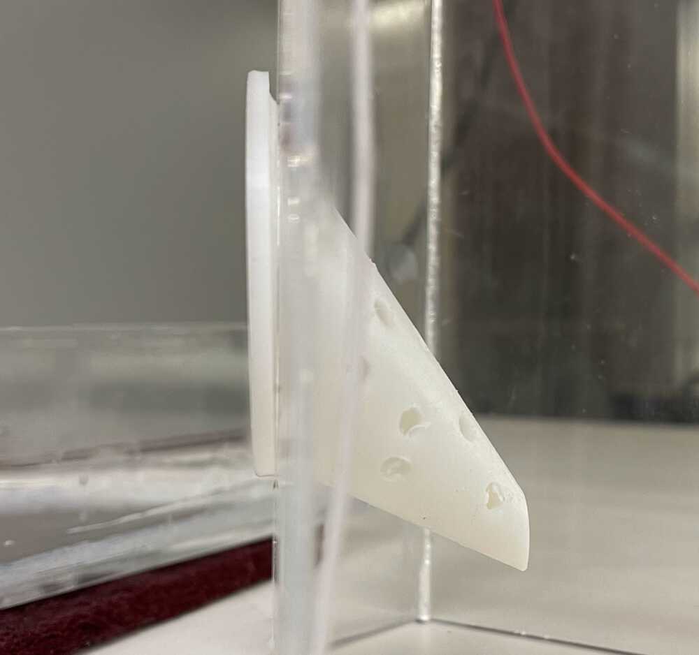
Plant Enclosures
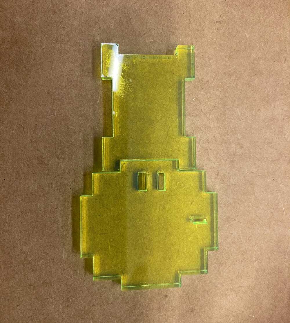
The next to last step in the project was to design and 3D print holders for the plants. I ran into a problem with the way I designed and built the physical system because I could not laser cut at an angle so I needed to design the holders with their center of mass behind and below the opening so that the plants would not tip it out of the hole. To do this I made a bugle-looking design (below) then drilled out the holes in it manually to save me some CADing time since I am still by no means an expert and didn't know how to quickly make a mesh pattern to allow the plant roots to grow through. In the end these turned out looking nice, however, they still tipped out, so for now I taped them down, however, I will probably add some sort of fastener to hold them in place, but allow them to be taken out still if wanted.
Final Build!
The last step in the process was to put everything together! This process consisted of putting copper tape on all the modules to allow them to conduct across pieces, connecting them internally with wires to make the circuits, attaching the control board on the top and connecting it to power and the water board, and finally stacking everything, filling it with water, adding the plants, and turning it on! This process took much longer than I expected and I ran into countless problems with holding true to my modular design. The first problem was actually making each layer conductive. For this prototype I opted to use copper tape since, however, I quickly found many imperfections in how level my acrylic was and the fluctuations in size and shape under different climate conditions. I spent some time trying to level things out by adding more coppy/solder in some areas, but as you can imagine, that is a finicky game that is not worth playing so for my final demo, I decided to weight the top to basically press the copper connections together using little signs that say "Modular Aeroponics". To the naive onlooker, this was a stylistic touch, but to me it was the pivotal piece that made my prototype work. For the next version of this project or for anyone else looking to do something modular like this, I discovered theses which would have been much more robust and asthetic looking than my feeble copper tape. Sometimes you gotta make due with what you've got though and for my final push that was copper tape. Besides that, my last be reflection on what I would have changed would be to include a way to add water, without picking up the whole stack of modules or removing a plant. I don't know how I overlooked this in my design, but a simple hole drilled through the back would have sufficed and could easily be corked.