This week, I made a first version of a PCB and sensor system that will serve as the main electronic control components of my final project Fabμbox spin-coater. More specifically, what I need is input from a rotary encoder in order to be able to determine the actual spin speed of the rotating shaft as well as a motor to rotate that shaft. This will allow me to send a desired spin speed to the microcontroller and based on the rotary encoder feedback, control the voltage output to the attached DC motor such that the desired speed is achieved.
While the PCB I present below already has both the components for an optical rotary encoder as well as the motor driver components, for this week's documentation, as it is input week, I will focus only on the encoder side of things, and discuss the motor driver features in next week's documentation.
2. PCB Design and Circuit Considerations
3. PCB Milling and Stuffing
4. Hardware Adjustments for Rotary Encoder Read-Out
5. Intro to Interrupt Service Routines
6. Programming the Encoder
Introduction to Rotary Encoders
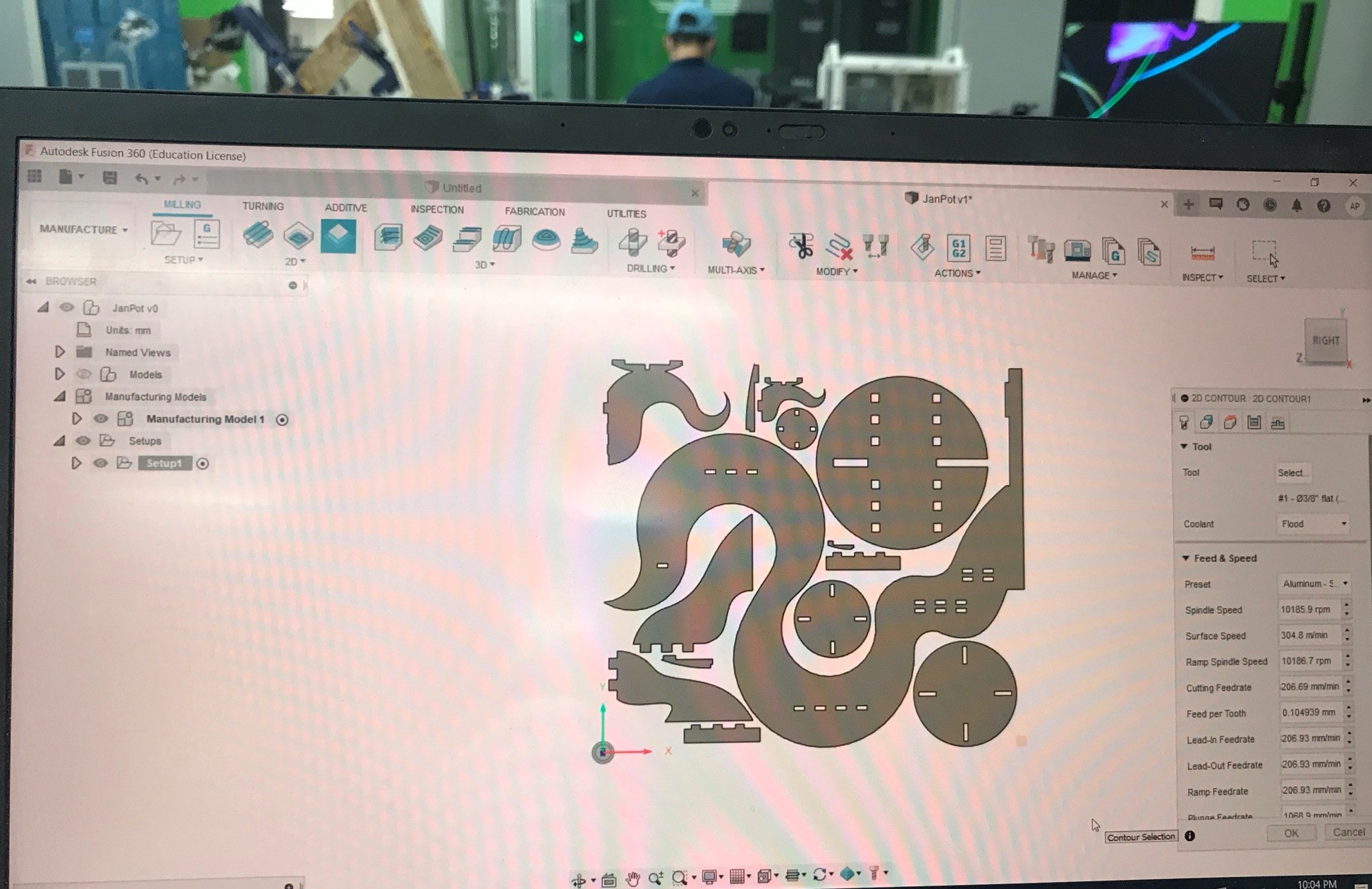
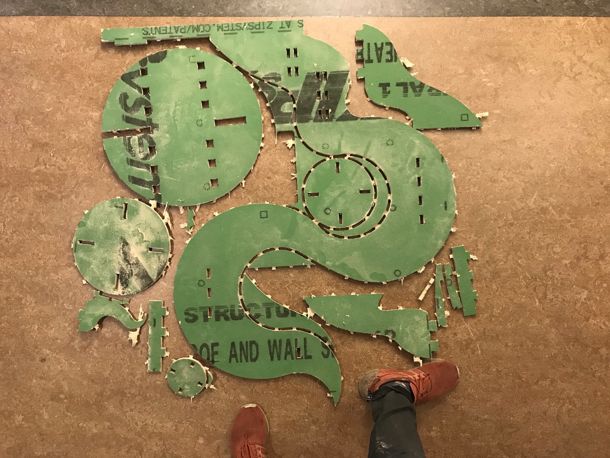
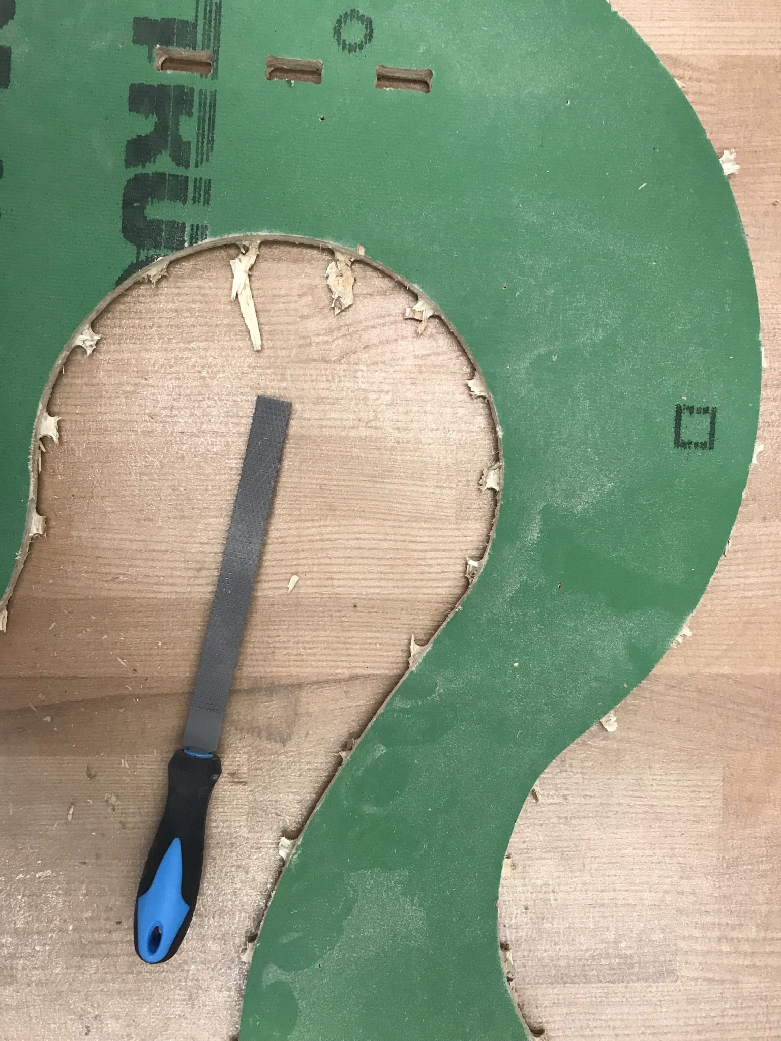
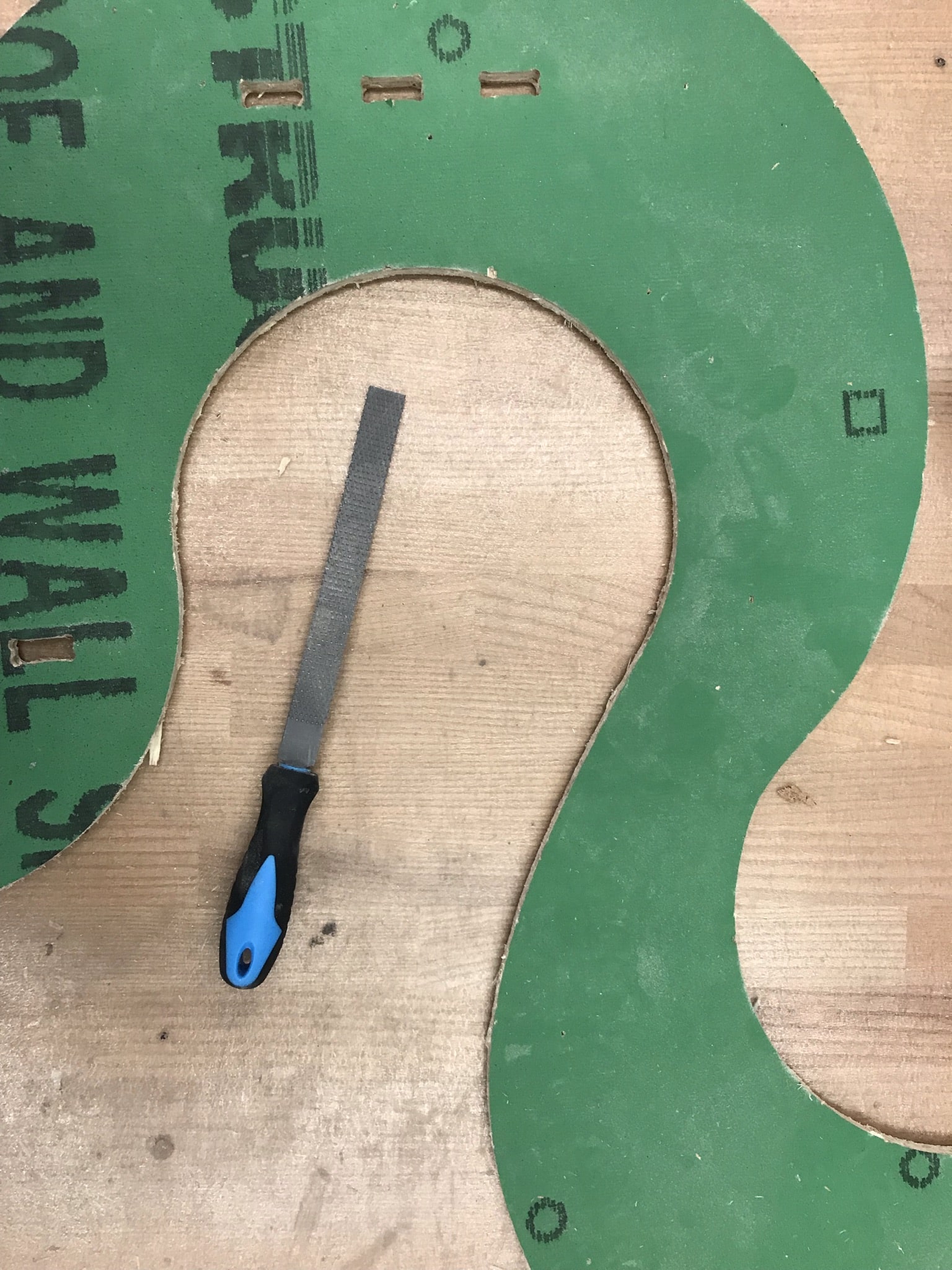
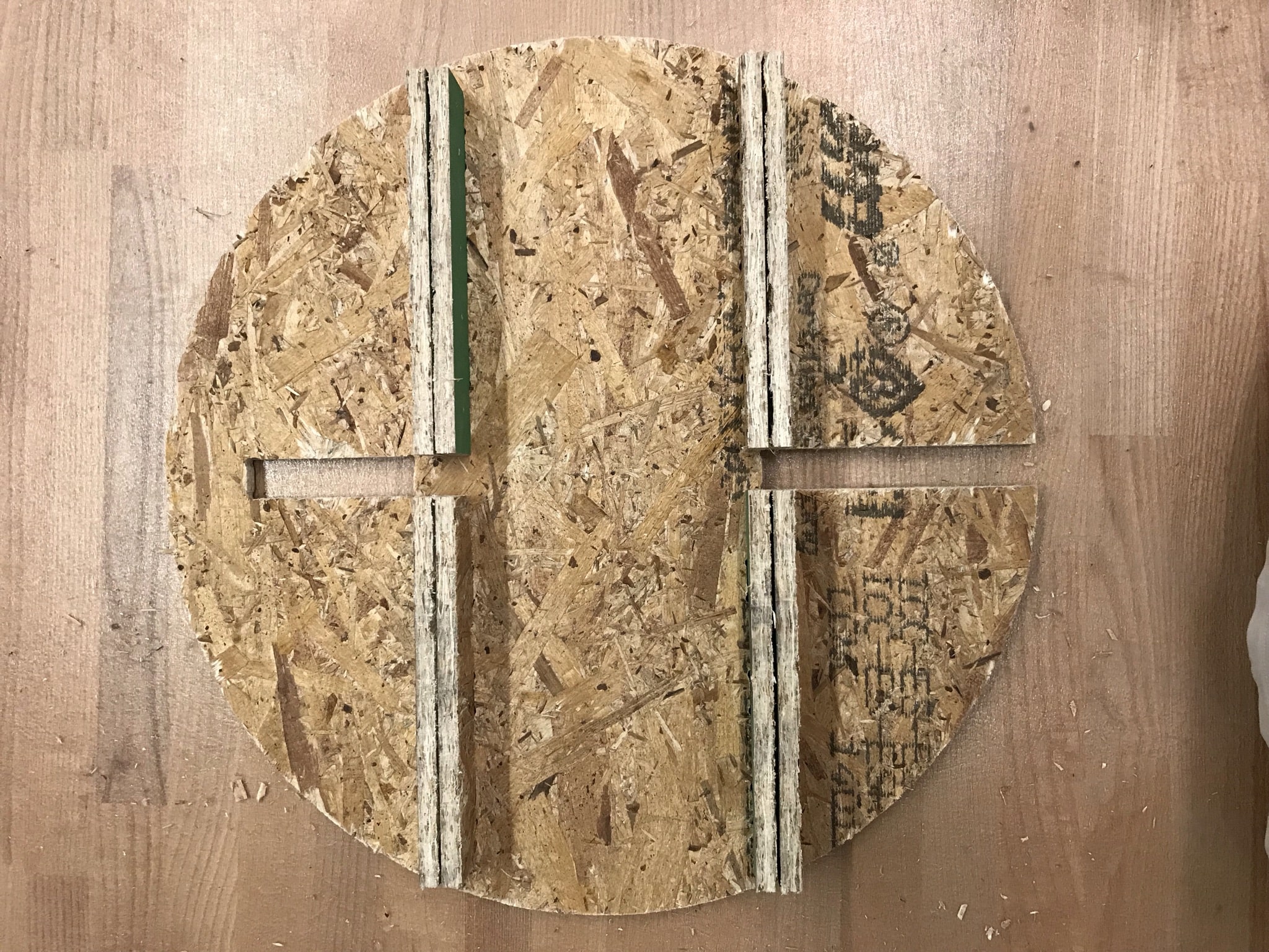
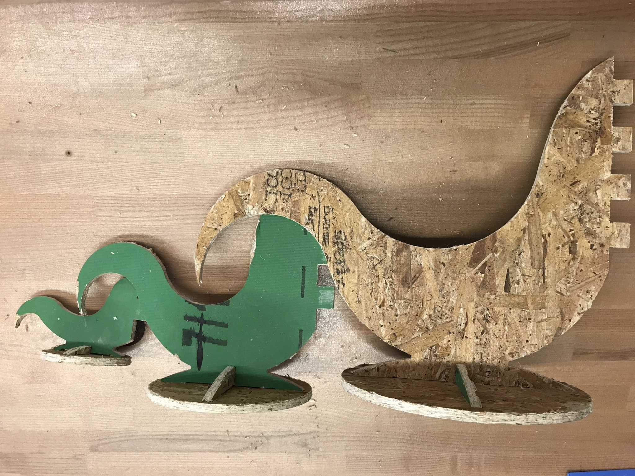
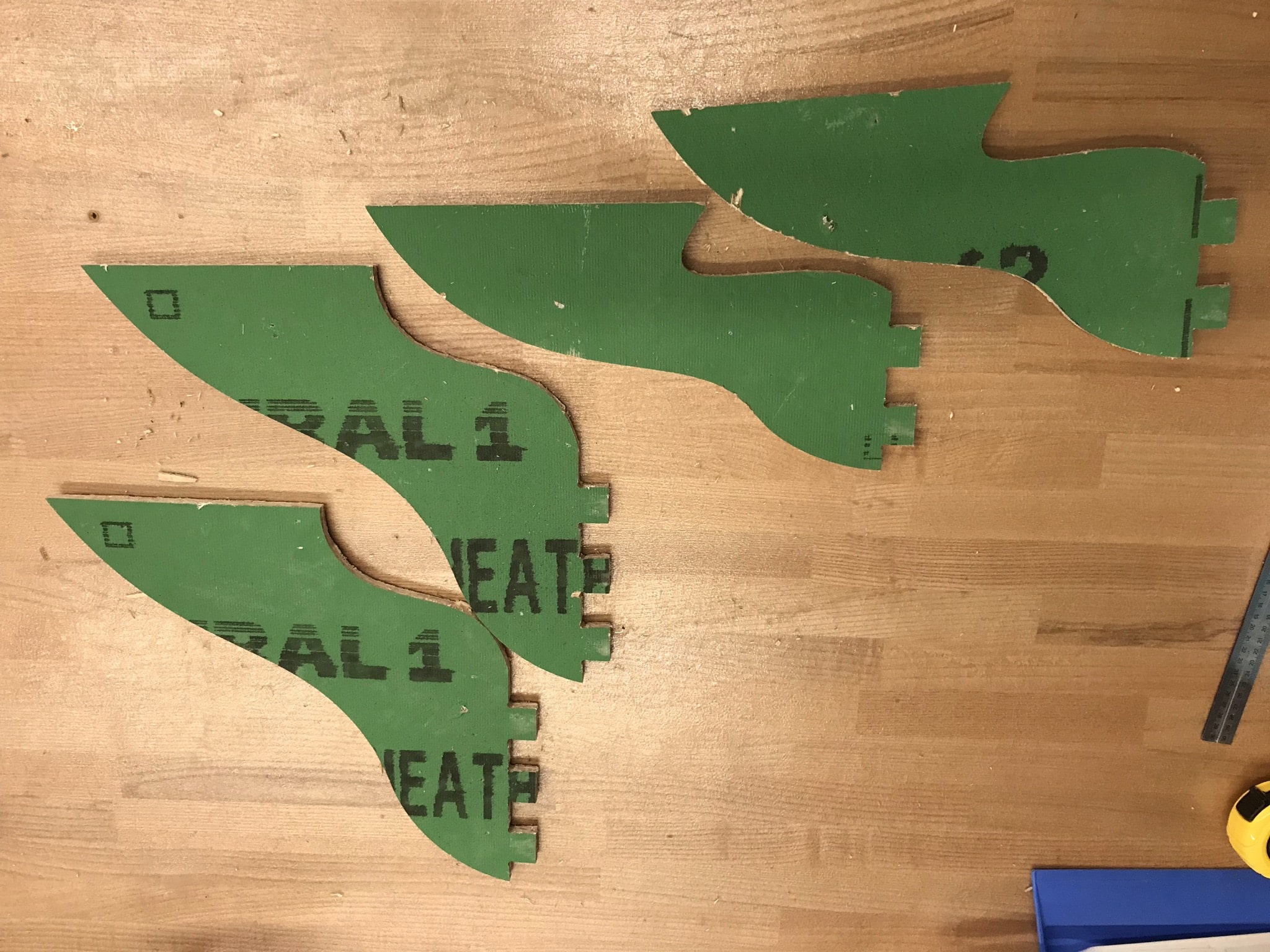
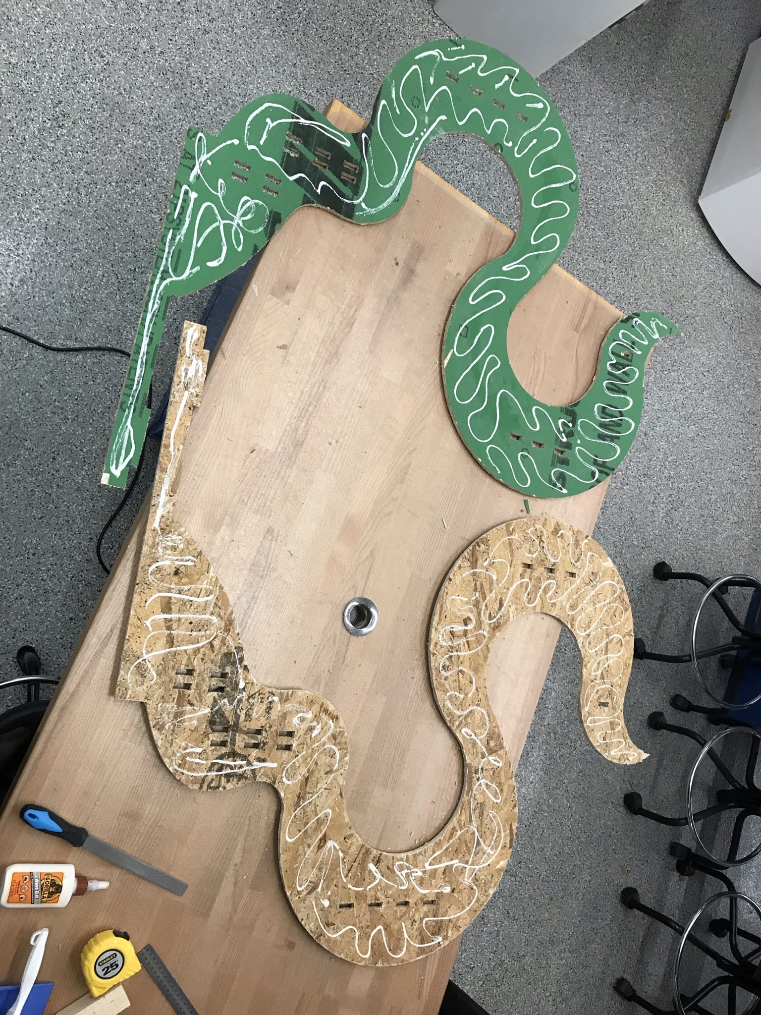
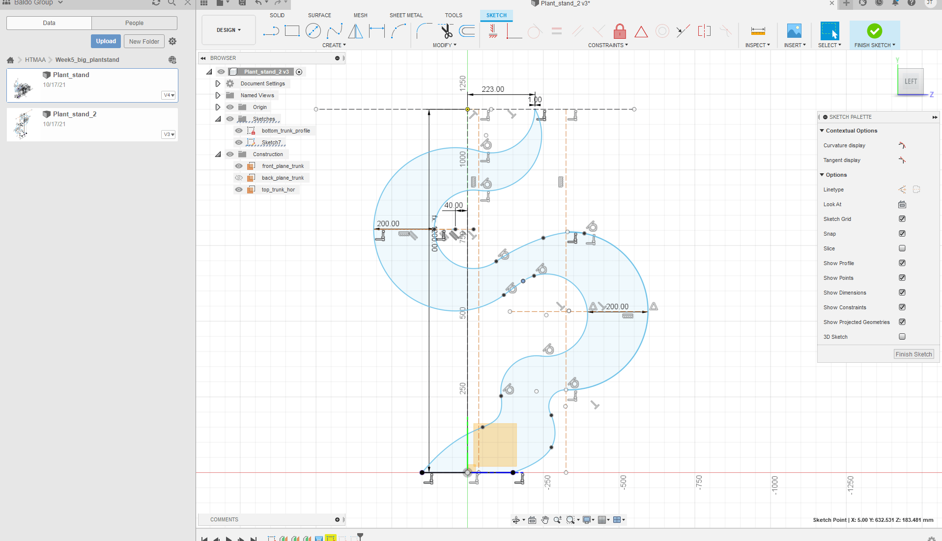
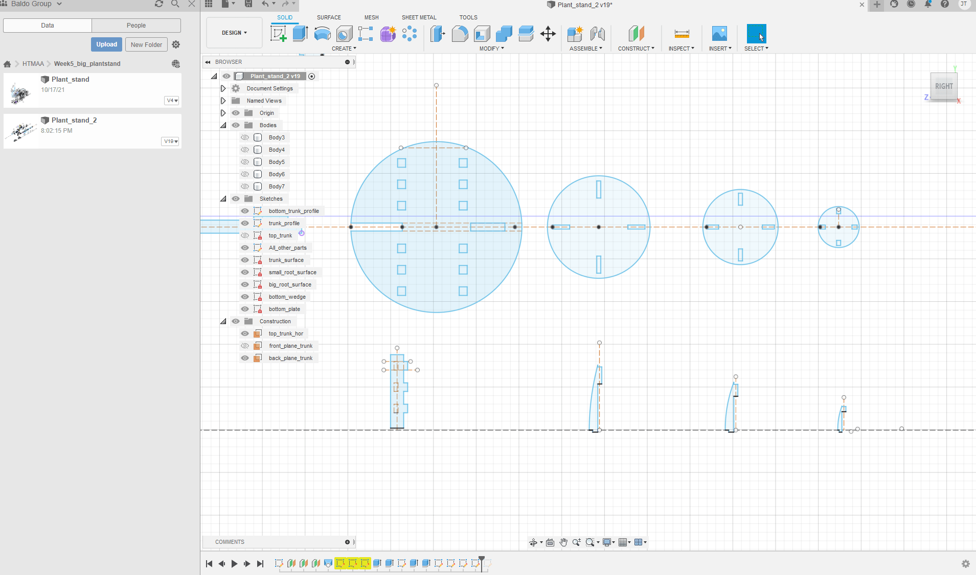
This week's assignment was to Make Something Big out of OSB (oriented strand boards) using a CNC mill. I decided to make a plant stand for my living room. My goal was to design it such that the plant stand blends in with the live plants themselves. Starting from a sketch on paper, envisioning a vine-like base structure, I designed the stand in Fusion360. Shown below are the main outline of the "trunk" as well as the plates and supports to place flower pots. The biggest challenge in this design was connecting and constraining the curved arches and splines in an aesthetically pleasing way. At first my main focus was on giving it a "geometric" feel by using only circular arches. However, connecting these tangentially proved to be very challenging in getting the overall desired shape and structure, so I inserted 3-point splines in between circular structure that allowed for a lot more flexibility in connecting parts of the trunk/vine together. All inside corners for press-fit tabs of the design had dogbone structures added to them as the machining tool cannot reach into the corners, thus a good press-fit cannot be ensured.

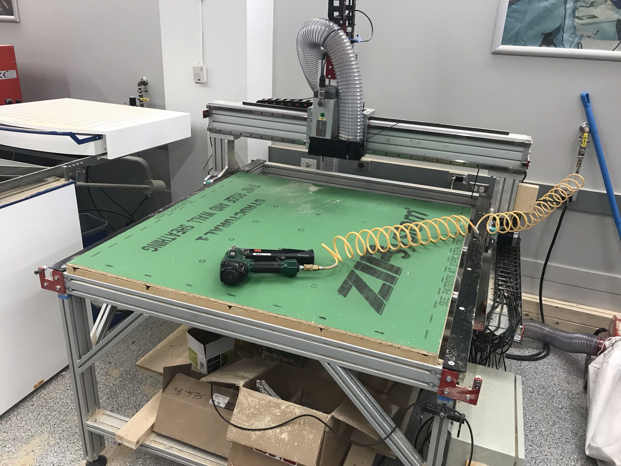
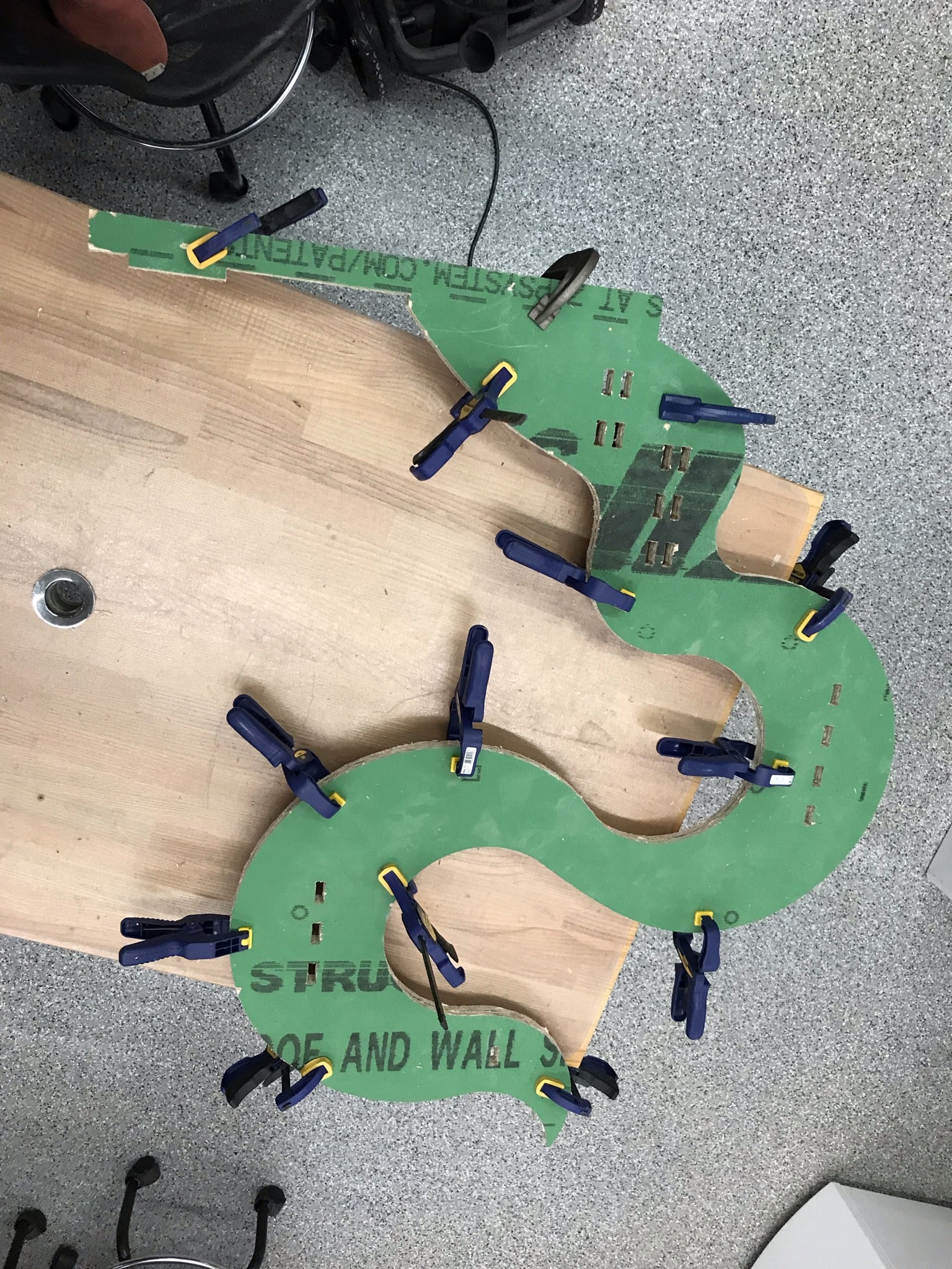
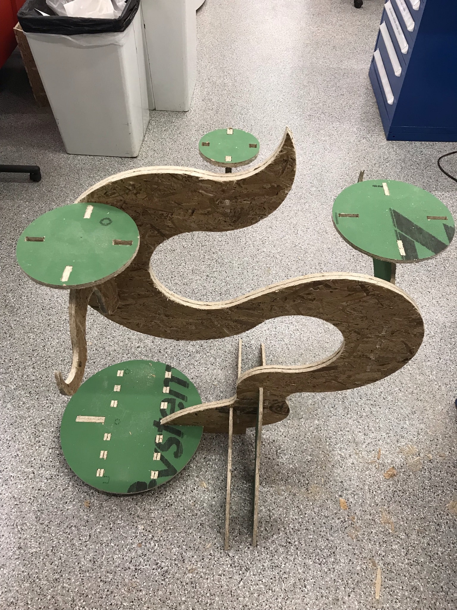
These parts were then further assembled and processed directly in the CAM section of Fusion360. Here, they were laid out in a material-efficient manner. Further, machining tools and tool paths for 2D contouring were defined. As a final step, all of this information was written into G-code readable by the Mach4 software controlling our Avid CNC mill shown below. Tools used for this job were 1/4 inch and 3/8 inch flat end mills for smaller and larger features, respectively. The OSB board was held down on the machining bed by plastic nails inserted with a nail gun. Special care needed to be taken of very small parts as they needed additional support to be held in place during machining.