This week, the second, output part of the PCB made last week is addressed. While last week's focus was on the input/sensing side of things, that is, the encoder, this week I worked on the motor control.
2. PCB Layout and Schematics: A4950 Motor Driver
3. Debugging Motor Drive Failure
4. Programming
4.1 Step 1: Motor Driver Code
4.2 Step 2: Link with Encoder Code
Brushed DC Motor Control Basics: H-Bridges
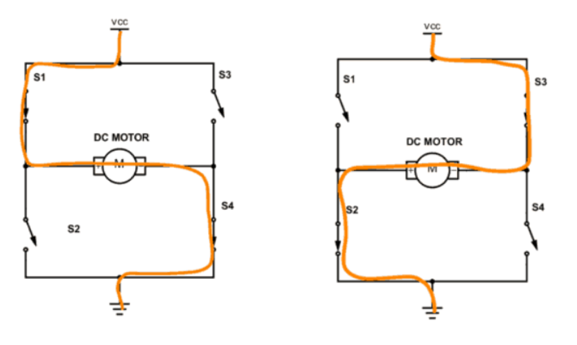
Driving brushed DC motors is very straightforward in the sense that they rotate by simply applying a voltage across them. The polarity of the applied voltage, that is, the direction in which current runs through them determines the direction of rotation. A so called H-bridge can be used to control the direction of rotation of a brushed DC motor. As schematically shown below, an H-bridge consists of four switches, typically transistors, that are opened and closed pairwise in order to switch the direction of current flow through the motor sitting in the center of the bridge. This constellation also gives the H-bridge its name, resembling a capital "H".
Image taken from here
The logic required for this precise pairwise switching of transistors in an H-bridge is implemented in DC motor driver ICs, such as the A4950 , which I used here and will be discussed in more detail below.
PCB Layout and Schematics: A4950 Motor Driver
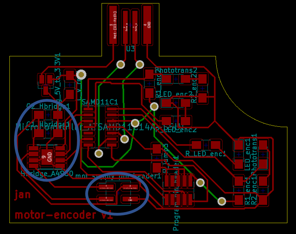
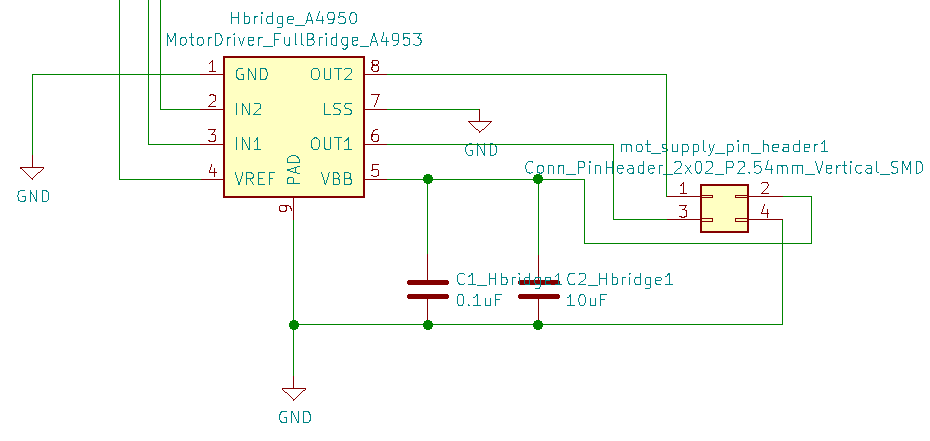
Highlighted below are the components on last week's PCB that enable driving my brushed DC motor. Namely, this is an A4950 motor driver, as mentioned above, with two capacitors in parallel to allow for steady power supply on pin VBB. This pin and GND will be connected to a pin header with the positive and negative poles of a 12V power supply attached. On the same pin header, the two poles of a DC motor will be connected, receiving voltage from pins OUT2 and OUT1 on the A4950. These are the two leads to the motor in the center of the bridge, as outlined schematically above.
The polarity and voltage level of these two leads is controlled by the input on pins IN1 and IN2 on the A4950, as following:
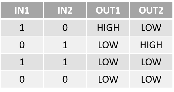
In summary, this means the motor will receive the voltage applied at VBB whenever IN1 and IN2 are not the same. Whenever IN1 and IN2 have the same value, no voltage is applied across the motor. How can this be used to control voltage levels received on the motor?
The voltage, that is, rotational speed of the motor, can be controlled by applying a PWM signal on either IN1 or IN2 while keeping the respective other IN1/IN2 always at 0. This will apply an average voltage to the motor according to the chosen ON/OFF ratio of the PWM signal. In the case of the SAMD11, the 8-bit DAC takes input values from 0 to 255. Thus inputting a PWM value of 125 on IN1 and 0 on IN2 will result in the DC motor being powered by about 6V (assuming a 12V power supply on VBB).
Last, VREF is tied to the 3.3V powering the SAMD11. The LSS pin is a sensing pin that can be used to limit the current flow through the motors. LSS is here simply tied to ground. In order to lower the current limit, a resistor between LSS and ground is inserted. Both the value of the resistor as well as VREF determine the current limit, the formula for which can be found in the A4950 data sheet.
Debugging Motor Drive Failure
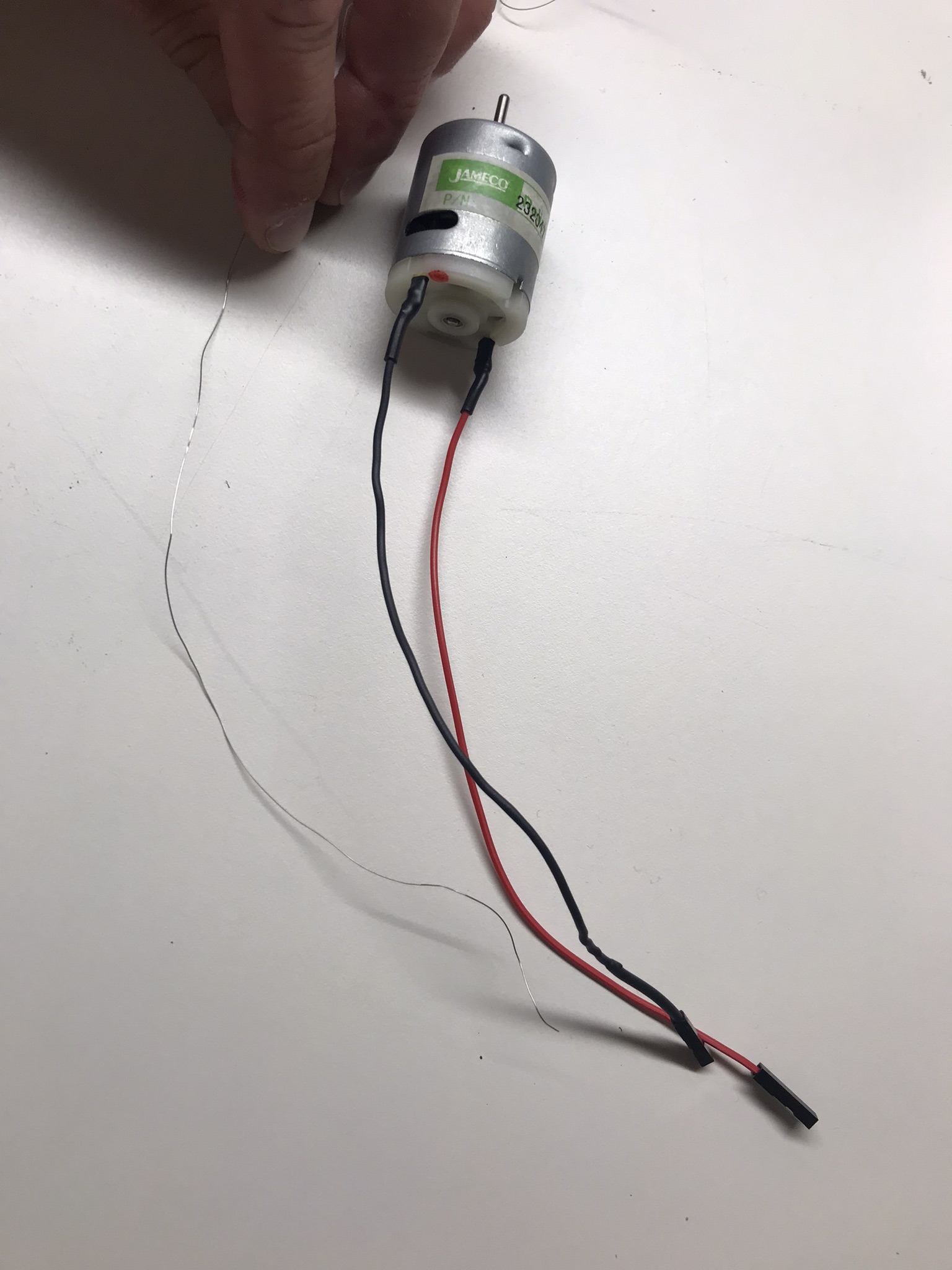
The brushed DC motors available in the EECS shop were the ones linked here . Running these directly from an A4950 was not immedietaly possible. Upon connecting the motor, the A4950 did not output any voltage to the motor despite opposite values input on IN1 and IN2. With Anthony's help I determined that this was due to the low resistance of only 1.5 Ohm across these motors, leading to the A4950 detecting this as a short circuit and thus operating in braking mode. In order to work around this issue, I got some Mylar wire from Dave. This is a high-resistance wire, shown in image below, that I replaced one of the cable leads to the motor with (packaged in shrink tube). Over a length of 6 inches this wire has a resistance of about 5 Ohms which was enough to allow the A4950 to go into operating mode.
An additional issue I faced, and haven't resolved yet, is the fact that the motor driver goes into chopping mode on occasion as it drives the DC motor used here. I presume this has to do with the currentn limit and I may have to increase the resistance on the motors to reduce current flow or increase VREF on the A4950 to allow for larger currents to flow.
Programming
Step 1: Motor Driver Code
The code to alternate the motor smoothly between clockwise and counter-clockwise rotation is very simple and pasted below:
          #define MOT_IN1 8
          #define MOT_IN2 9

          void setup() {

            pinMode(MOT_IN1,OUTPUT);
            pinMode(MOT_IN2,OUTPUT);
            Serial.begin(9600);
            delay(10);
          }

          void loop() {
            int i = 0;
            for (i=20;i<60;i+=1){
              analogWrite(MOT_IN2,i);
              analogWrite(MOT_IN1,0);
              delay(150);
            }
            i = 0;
            for (i=20;i<60;i+=1){
              analogWrite(MOT_IN2,0);
              analogWrite(MOT_IN1,i);
              delay(150);
            }
          }
The video below shows the resulting motor rotation in both directions.
Step 2: Link with Encoder Code
When linking this code with the encoder code shown last week my motor/encoder system can be used to accurately read out motor spin direction and speed. The motor used here is rated at a maximum spin speed of 19,850 rpm at maximum efficiency. At the maximum PWM input (or simply digital HIGH), my encoder readout was about 19,400 rpm. With this value being very close to the maximum value the motor could achieve under ideal conditions, this shows that my encoder system works well and does not appear to miss counts even at very high spin speeds, thanks to the interrupt service routine implemented in its operation.
The video below shows read-out of both spin speed and direction of my DC motor with the encoder wheel attached, spinning at about 3-5 mm above my optical encoder system.