This week, I made a first version of a PCB and sensor system that will serve as the main electronic control components of my final project Fabμbox spin-coater. More specifically, what I need is input from a rotary encoder in order to be able to determine the actual spin speed of the rotating shaft as well as a motor to rotate that shaft. This will allow me to send a desired spin speed to the microcontroller and based on the rotary encoder feedback, control the voltage output to the attached DC motor such that the desired speed is achieved.
While the PCB I present below already has both the components for an optical rotary encoder as well as the motor driver components, for this week's documentation, as it is input week, I will focus only on the encoder side of things, and discuss the motor driver features in next week's documentation.
2. PCB Design and Circuit Considerations
3. PCB Milling and Stuffing
4. Hardware Adjustments for Rotary Encoder Read-Out
5. Intro to Interrupt Service Routines
6. Programming the Encoder
Introduction to Rotary Encoders
Generally speaking a rotary encoder is a stationary sensing device that outputs alternating HIGH and LOW signals in response to a rotating reference, such as for example the rotating shaft of a motor. Detecting these binary signals allows for derivation of rotational speed and direction (more on that below) by relating signal counts to the time passed between counts.
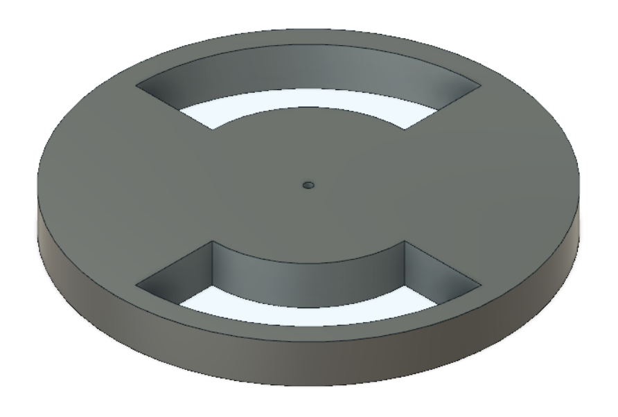
The two most common kinds of rotary encoders are magnetic and optical. Magnetic encoders typically use Hall-effect sensors that output a count every time a permanent magnet mounted on the rotating shaft passes over the stationary Hall-effect sensors. Optical encoders use stationary light sources, for example LEDs, that reflect light off an encoder wheel mounted on the rotating shaft of a motor, such as the one I designed shown below on the left for my optical encoder system. Light detection in my case is carried out by using a phototransistor which varies resistance depending on the amount of light impinging on it. As the encoder wheel rotates over the LED and phototransistor, resistance is high as the gap areas are located above them (low light reflection) and resistance is low as solid areas are above them (high light reflection). My encoder wheel will thus output two HIGH and two LOW signals per revolution. While it is evident how this allows us to get the rotational speed using clocks on a microcontroller, how does this allow us to detect the direction of rotation?
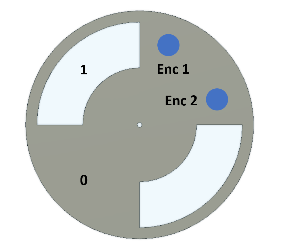
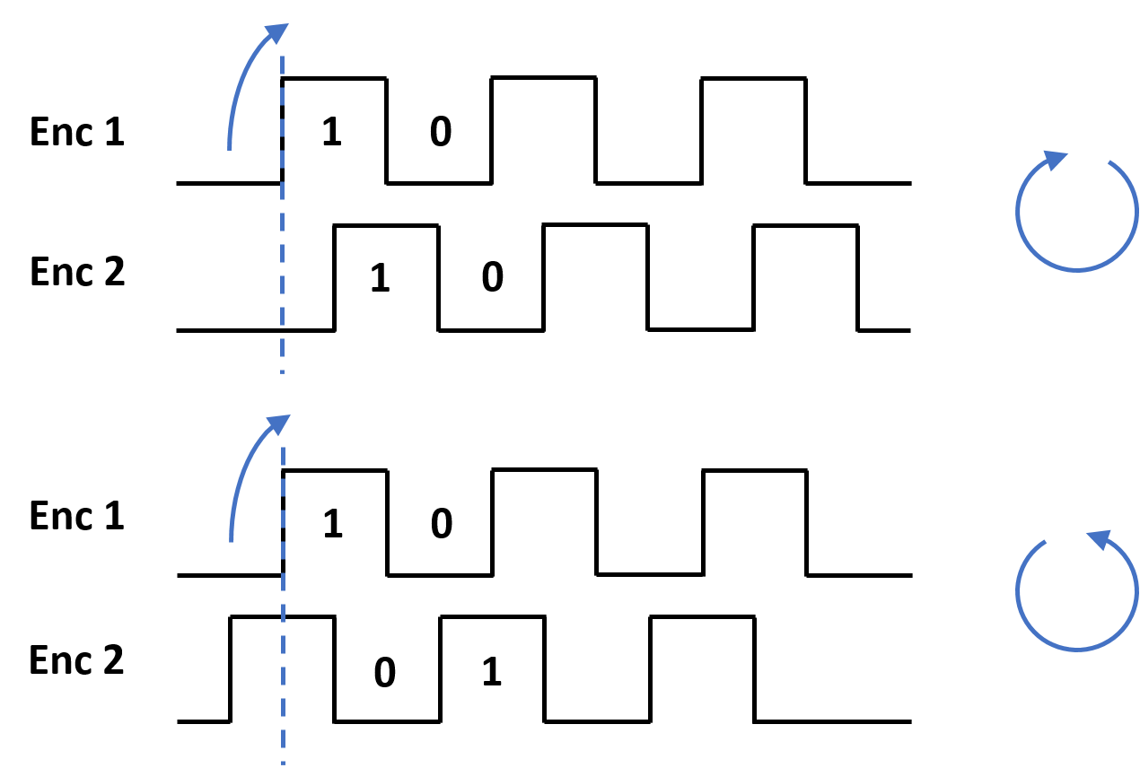
In order to detect direction of rotation, two encoder units are required. In the above top view of the encoder wheel, as depicted on the right-hand side, I indicate the physical position of the stationary encoder units by the two blue circles. As the encoder wheel rotates over these two units, comprising an LED and a phototransistor each, the HIGH/LOW signals of each unit are phase shifted with respect to each other. This can be used to derive rotational direction in the following, depicted schematically below: As encoder 1 goes from LOW to HIGH, we check for the state of encoder 2. In my example, if encoder 2 is LOW when encoder 1 changes to HIGH, the wheel is spinning clockwise. If encoder 2 is HIGH when encoder 1 goes HIGH, the wheel is spinning counter-clockwise.
The physical implementation as well as the code required to compute rotational speed and direction from the concepts described above will be discussed in the following.
PCB Design and Circuit Considerations
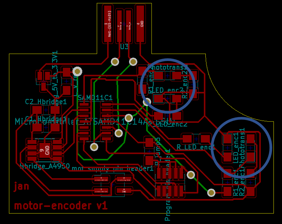
An overview of the entire PCB schematics and board layout are shown below. As mentioned above, this contains components both to drive a DC motor as well as the electrical components for the optical encoder system. The circular cut-out in the top-right corner of the PCB is where the motor will be located to rotate over the two adjacent LED/phototransistor units, circled in blue on the board layout.
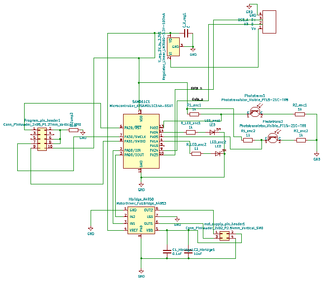
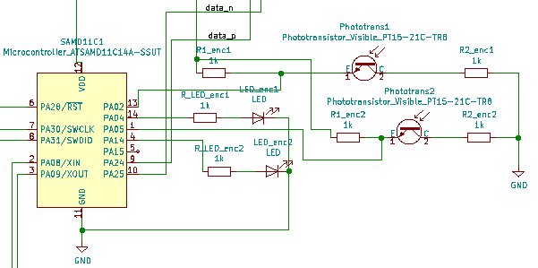
The parts of the schematic that make up the optical encoder system are shown below. Each encoder consists of an LED that will be turned on to reflect light off a rotating wheel attached to the motor shaft. The reflected light is detected in the second part of each encoder, a phototransistor. As sufficient light strikes the phototransistor, the resistance drops by several orders of magnitude. This change in resistance can be measured on a microcontroller pin using a voltage divider on which I will elaborate below.
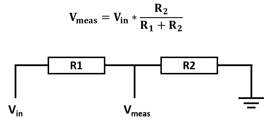
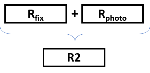
Below shown on the left is the general circuitry of a voltage divider as well as the formula for the voltage that can be measured between R1 and R2 on our microcontroller pin. The measured voltage is dependent on both the magnitudes of R1 and R2, where R1 here is composed of the sum of the variable reistance of the phototransistor as well as a fixed resistor connected in series. I started with 1 kOhm for both resistors R1 as well as the fixed resistor part of R2. Appropriate values of these resistors will have to be determined experimentally depending on the change in resistance that can be achieved on the phototransistor with the reflectance off the encoder wheel and will be discussed in more detail below. While we would ideally like to measure a digital signal on the encoder units, as explained above, the measured voltage is an analog signal. I will discuss below how to handle this and why a digital signal is preferred.
PCB Milling and Stuffing
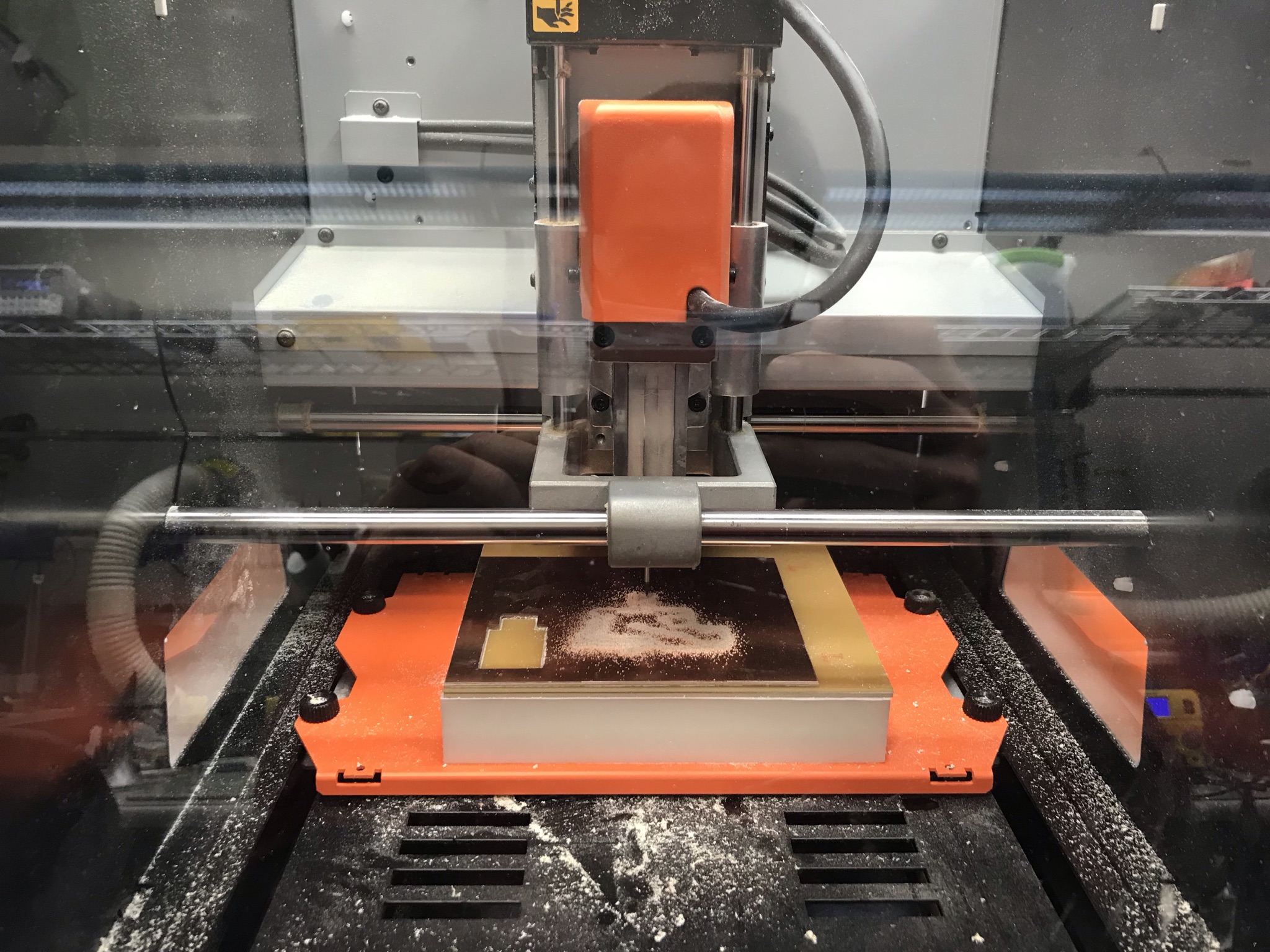
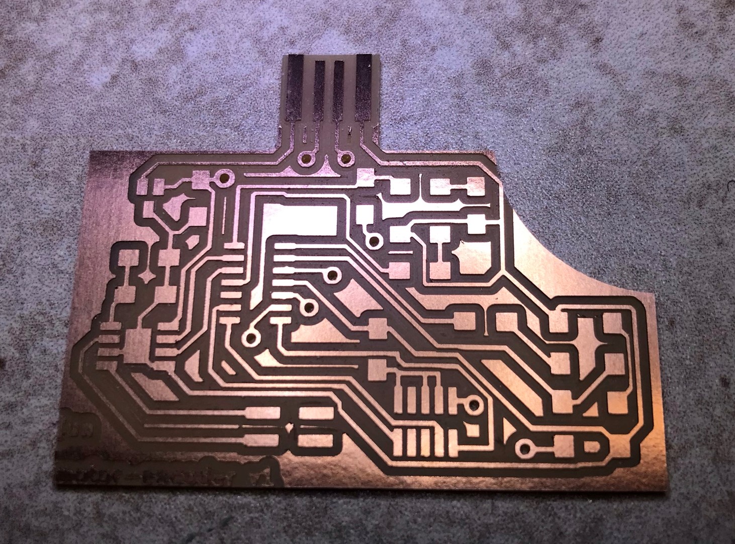
I milled this board in the Roland SRM-20 using Mods. Shown below is the PCB in the milling process and how it came out before cleaning up the edges

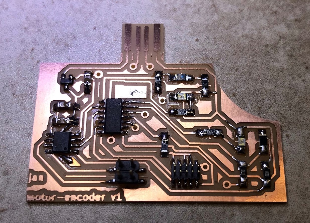
Depicted below on the left-hand side is the board after cleaning up and on the right-hand side after stuffing of the top-layer components.
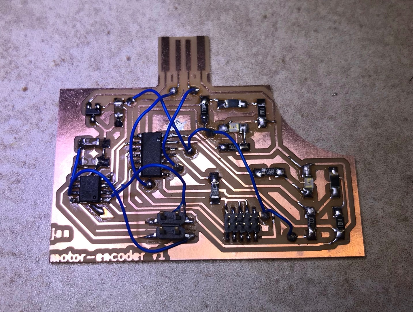
As shown in the PCB design section above, this PCB was designed to be a two-sided board using vias. One requirement of milling a board on the Roland with Mods, that I hadn't taken into account, is the fact that symmetry in the x-axis is needed in order to be able to flip the board inside the cut-out of the stock to ensure alignment of the bottom tracks with the vias. This was not possible with my current board design, so I decided to make it a 1.5-sided board using jumper cables to create the connections that were meant to be made using bottom-side tracks. Alternatives would have been to re-design the board with a symmetry along the x-axis and re-mill on the Roland, or use the current design on the Othermill PCB mill with Gerber files which can account for any kind of assymetry within its inbuilt software when making a two-sided board. The final result is shown below.
Hardware Adjustments for Rotary Encoder Read-Out
First attempts to read out the encoder signal failed due to no variation between read-outs on the voltage divider for reflect vs. transmit sections of the encoder wheel located above the phototransistor. Further, the detected signal was always high, close to 1023 counts (the maximum on the SAMD11 10-bit ADC). This means that the resistance on the phototransisor was both very high in comparison to R1 on the voltage divider and also not sufficiently varied when being struck by light reflected off the encoder wheel.
First, this indicated that the encoder LEDs were not bright enough. I thus de-soldered the initial weak green LEDs I had stuffed on my PCB, and replaced them with these much brighter, cold-white 5000K LEDs . The footprint of these LEDs is slightly different, with a longer anode pad. I thus had to place a little piece of Kapton tape between pads below the white LED to prevent creation of a short circuit of the cathode with the track running between the anode and the cathode pad. The difference in brightness between the white and the green LEDs is very clearly visible in the short video below.
To increase LED brightness even further I reduced the resistor in series with the LED down to 100 Ohm.
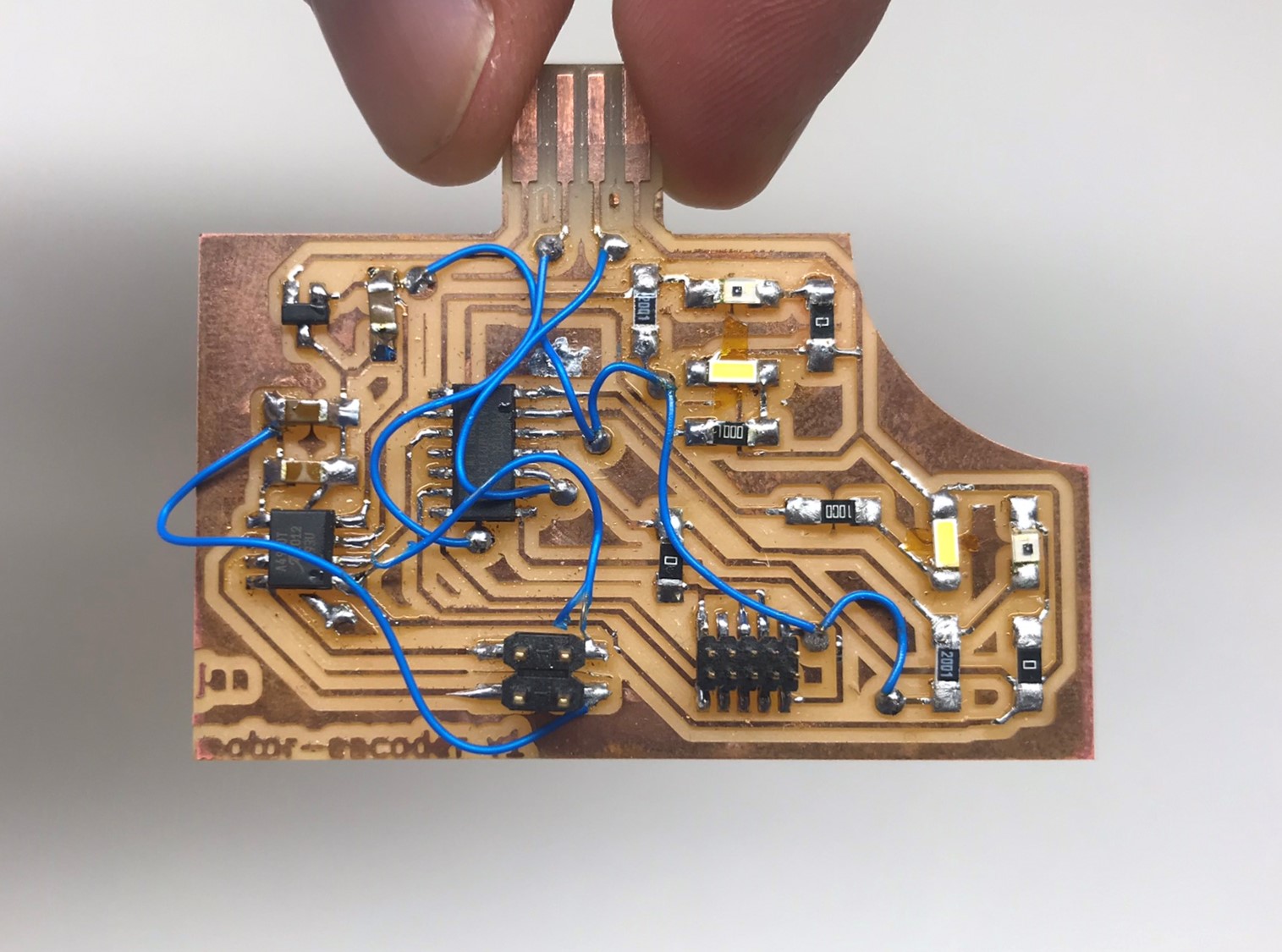
While these new LEDs were strong enough to generate a difference between reflect and transmit sections, the difference in analog reads was still only between 800 and 1000. In order to further improve this, I first dropped the fixed resistor forming R2 in series with the phototransistor on the voltage divider from 1 kOhm to a 0 Ohm resistor. This reduced my measureable reflect count down to about 500-600. While this is in principle good enough to distinuigh between reflect and transmit state, the range needs to be extended a little bit further in order for me to be able to read out the signal as a digital 0 and 1. Why is this important? Before I get to that in the section below, I will finalize here the description of my hardware modifications: The last component I played around with was R1. Increasing R1 too much, moves the entire signal range down. However, I found a sweet spot of 2000 Ohm for R1 where I get an analog signal range between about 200 in reflect regions and 900 in transmit regions. This is well in the range of being possible to read out as a digital signal. The final fucntional version of my PCB is shown below.
As a final note, had I not managed to move my signal into the correct range by playing around with the LED and resistor values, what would have been my options? First, I had actually tried to use the comparator on the SAMD11 to get a digital output signal. Here, one can arbitrarily define a reference voltage in the middle of the two signals and simply get a digital output on whether the value is larger or smaller than the reference. While this can be done with the help of the SAMD11 data sheet, and going through all registers required to set up the comparator correctly, it does requires some experience in writing directly into the SAMD11 registers. In my case, I destroyed the bootloader a few times while trying to set up the comparator correctly, and finally decided to go with hardware modifications. Second, an external comparator, like an Op-amp could be used to transform the analog input into a digital signal. In my case this would have required re-milling and stuffind my PCB, so I was glad I managed to fix things simply by adjusting components on my board.
Intro to Interrupt Service Routines
In the case of fast rotational movement it is possible that one starts missing counts in the case of the analogReads just running in series with the rest of the code, especially if further processing is carried out. In order to still accurately measure spin speed with an encoder, this can be resolved by implementing an interrupt service routine (ISR), the code for which will be shown in the section below. An interrupt pin triggers a function, the service routine, immediately and every time a defined event occurs on the pin, as opposed to running synchronously with the rest of the code. Interrupt pins can be set up only on change in digital signal input, hence the importance of being able to read out my optical encoder signal as a digital HIGH and LOW. In the same way commercial, e.g. magnetic encoders, will typically do some internal processing on their analog input to pass out a digital signal. The event triggering the interrupt function can be either a change from only HIGH to LOW on the interrupt pin, or vice versa, or a change in either direction. The code in the interrupt routine will then be executed before regular code execution resumes.
Programming the Encoder
The code to set up my encoder system on the PCB shown above using an ISR is pasted below:
          // Define pins on MCU
          #define ENC1 2
          #define ENC2 5
          #define LED_ENC1 4
          #define LED_ENC2 14

          //Define other constants
          #define UPDATE_FREQUENCY 1 // frequency of motor rotation speed updates in 1/s

          // Initiate encoder counter
          long encCount = 0;
          long encCountOld = 0;
          long rot_speed = 0;
          long timestamp = 0;

          void setup() {

            // Set up pins for inputs and outputs
            pinMode(ENC1,INPUT);
            pinMode(ENC2,INPUT);
            pinMode(LED_ENC1,OUTPUT);
            pinMode(LED_ENC2,OUTPUT);

            // Initiate serial monitor
            Serial.begin(9600);
            delay(10);

            // Turn on encoder LEDs
            digitalWrite(LED_ENC1,HIGH);
            digitalWrite(LED_ENC2,HIGH);

            // Set up one encoder pin as interrupt on RISING, i.e. pin goes from LOW to HIGH
            // can also trigger on CHANGE giving us 4 counts per revolution instead of 2
            attachInterrupt(digitalPinToInterrupt(ENC1),encUpdateCountDir,RISING);
            // attachInterrupt(digitalPinToInterrupt(ENC1),enc1Update,RISING);
            // attachInterrupt(digitalPinToInterrupt(ENC1),encUpdateChange,CHANGE);

            timestamp = millis(); // Initialize timestamp for rotation speed updates
          }

          void loop() {

            long timeDiff = millis() - timestamp;

            if (timeDiff >= 1000 / UPDATE_FREQUENCY){
              long timeDiff_s = timeDiff/1000;
              long encDiff = encCount - encCountOld;
              // this gives rotation speed in revolutions per minute since we get 2 counts per revolution
              rot_speed = (encDiff*60)/(2*timeDiff_s);
              encCountOld = encCount;
              timestamp = millis();

              if (rot_speed > 0){
               Serial.print("Motor is spinning clockwise at: ");
               Serial.print(rot_speed); Serial.println(" rpm");
              } else if(rot_speed == 0){
                Serial.print("Motor is not spinning.");
              }else{
                Serial.print("Motor is spinning counter-clockwise at: ");
                Serial.print(-rot_speed); Serial.println(" rpm");
              }
            }

          delay(1000);

          }

          void enc1Update(){
             encCount++;
          }

          void encUpdateCountDir(){
             if (digitalRead(ENC2) == LOW){ // ENC1 state will always be HIGH here since interrupt is triggered on RISING
              encCount++; // differing state means disk rotating clockwise --> define here as positive rotation
             } else{
              encCount--; // same state means disk rotating counterclockwise --> define here as negative rotation
             }
          }


          // Use this function to detect counts on any change in state on encoders -> gives 4 counts per revolution
          void encUpdateChange(){
             int enc1state = digitalRead(ENC1);
             int enc2state = digitalRead(ENC2);
             if (enc1state != enc2state){
              encCount++; // differing state means disk rotating left --> define here as positive rotation
             } else{
              encCount--; // same state means disk rotating right --> define here as negative rotation
             }
          }
Finally, implmenting the code shown above alongside the hardware changes, I was able to read out both spin speed and direction as the encoder spins over my optical encoder system, as shown in the video below. Next week, as I try to read out a 20,000 rpm motor with this setup, the value of going through the trouble of setting up an ISR will become clear!