Final project:
ideas and elements
I want to make a CNC that plants, waters, monitors, and harvests things I can eat automatically.
I realized it is a much bigger project than I think it was...
Idea:
To Do:
1) Planting tool head
2) Watering nozzle
3) Harvesting tool head
4) Sensor bundle (moisture, pH, temp, etc)
5) Camera and image processing
6) Cellular module and a website for livestream data?
7) Maybe a user interface
not reinventing CNC control so need to talk to Jake...
What this project really is:
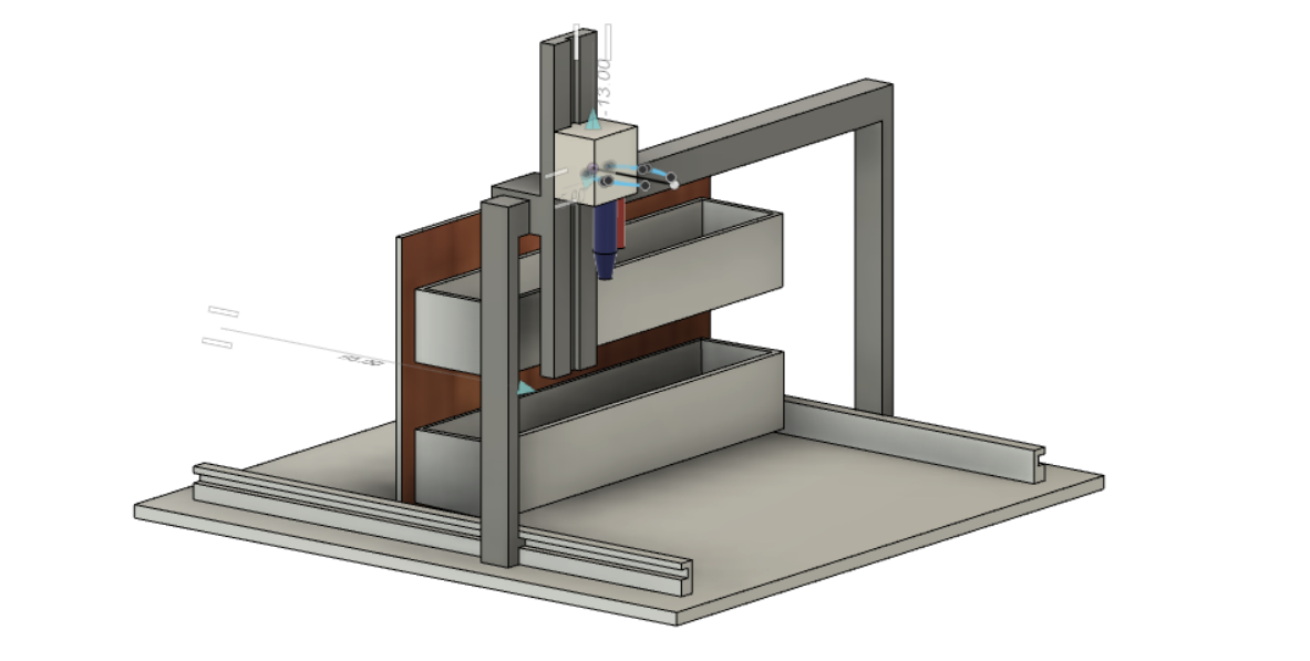
This project really turned into reinventing the motion system of a 3 axis cnc. I originally think it was easy to drive 3-4 motors. In addition to motors, I will construct a frame with 8020 and 3D printed parts, pulley, and acrylic cutouts. The documentation is more of an afterthought because I ran into serious project management/planning issues. To summarize my struggles, I failed to visualize how many mechanical parts I will need to construct a somewhat solid/rigid cnc framework that can be of use for anything (i.e., not a piece of shit.) It is a CAD nightmare, as I did not design/set most of the dimensions from the beginning. There are so many mounts, brackets, and pulley, and spacers I needed to design around my existing materials (I stole 8020, stepper motors, lead screws, motor couplers, and lead screw nuts from Anthony).
Materials:
aluminium 8020
stepper motors*4
Gikfun 12V DC peristaltic pump
Aokin linear bearings
Kootans L brackets for 8020
Songhe soil moisture sensors (capacitive sensors can be made in house)
unknow lead screws and nuts (from some old 3d printer)
HTMAA pcbs
acrylic cutouts (laser cutting)
3D printed brackets and mounts (stratasys with dissolved support)
various M5 and M3 screws/nuts
OSB and some paints
body
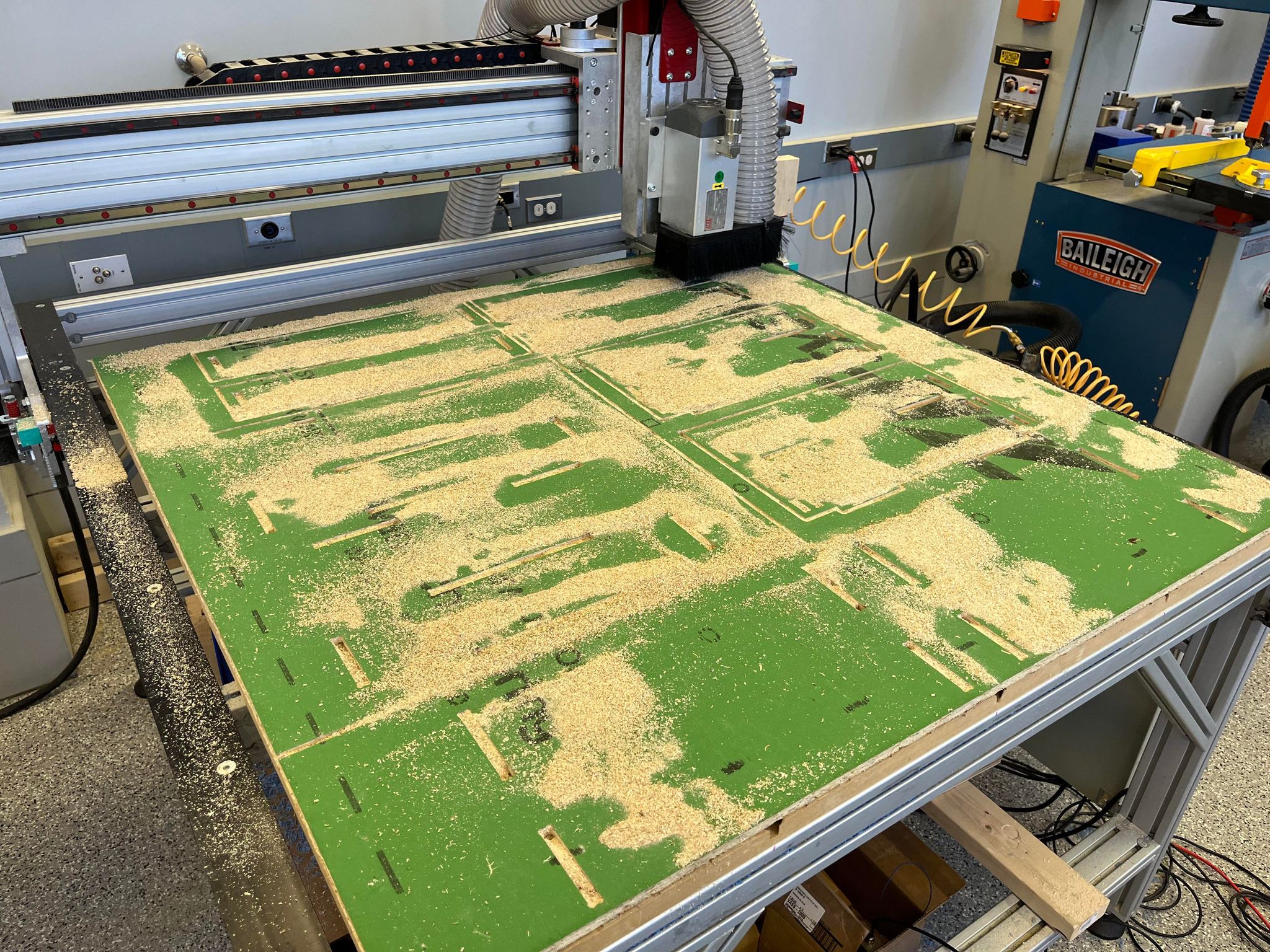
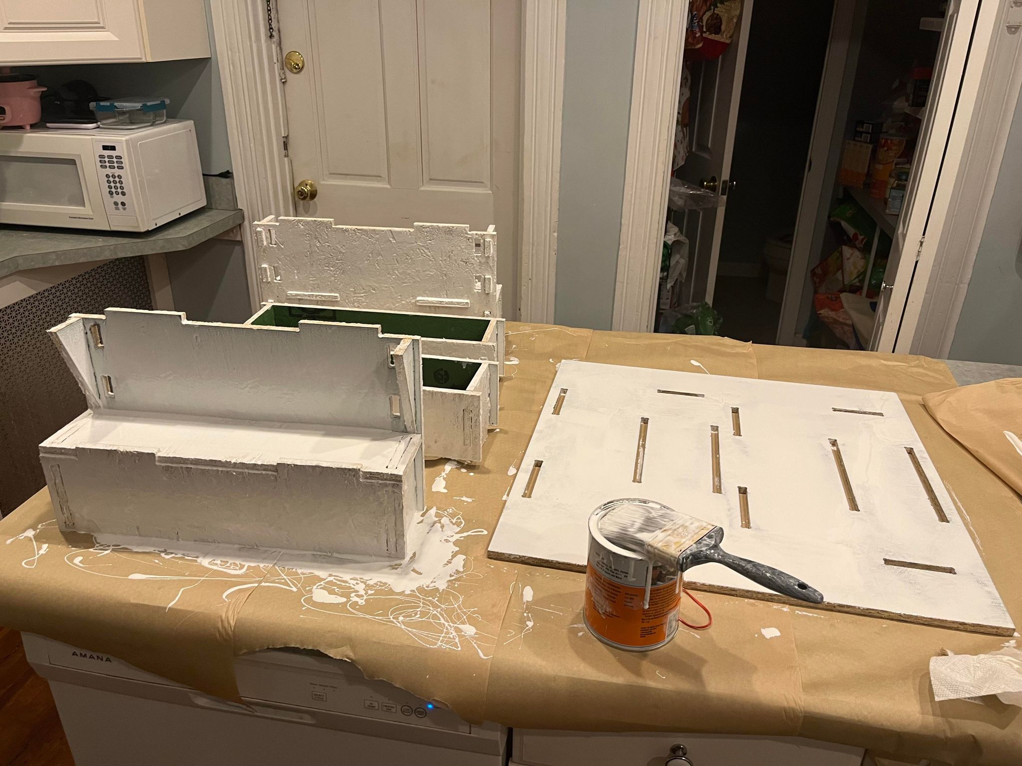
The body of the farm is intended to host plants. To do that and make sure OSB last, I did quite a bit of sanding and bought a can of rubberized coating to coat OSB to ensure that they can last longer given moisture can delaminate OSB rather quickly.
locomotion
pulley
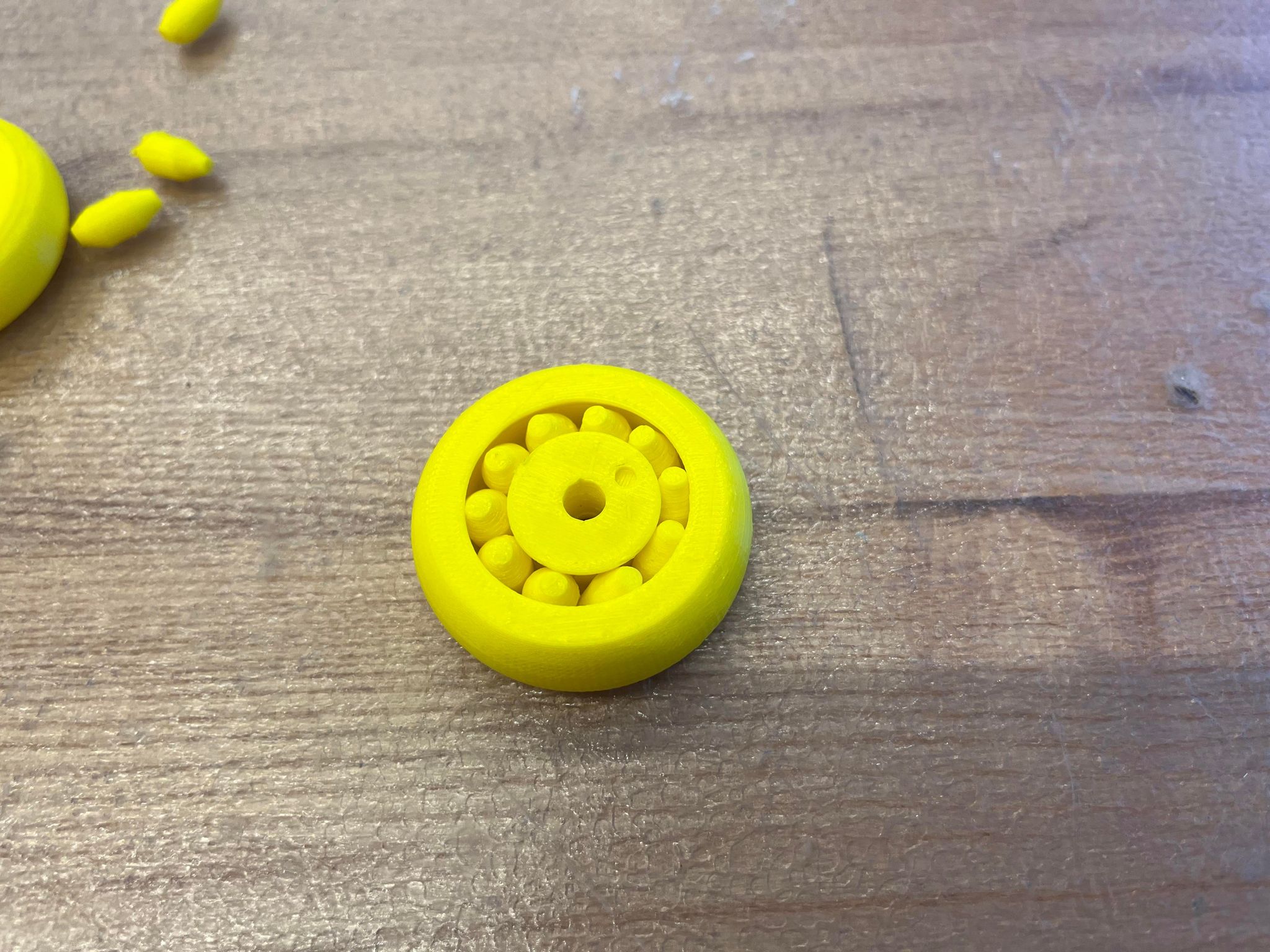
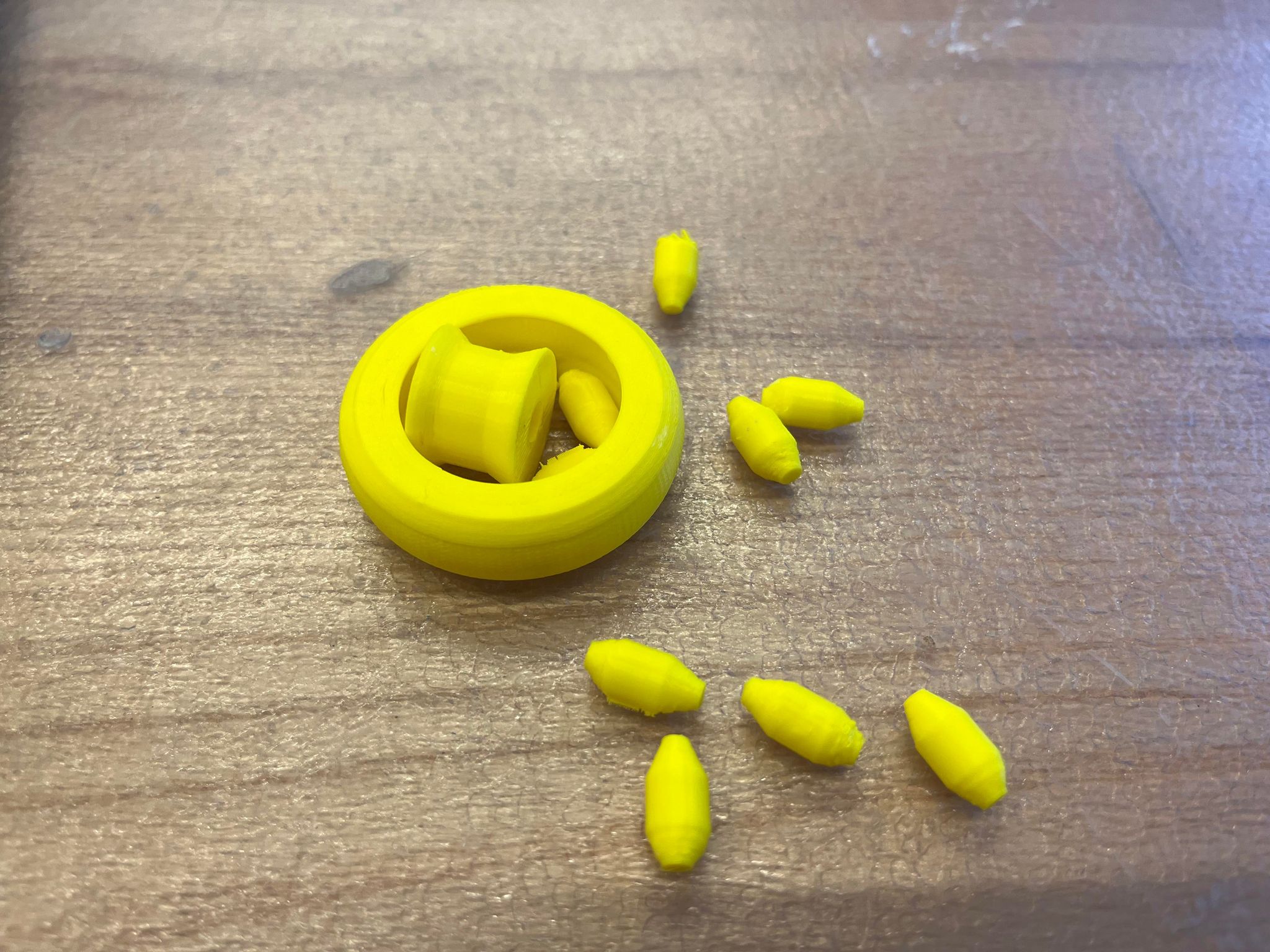
I spent a lot of time trying to get a 3D printed pulley to work. The truth is, due to the tolerance of filement printing, 0.4 mm was the smallest gap sindoh was able to print detachable parts (0.2, 0.3, 0.35, 0.4, 0.5 mm were tried). Any part gap smaller than 0.4 mm was either too hard to turn or the inner and outer bores would fuse together, creating one solid peice. I did get one prototype working, see the video below. However, this had a sad ending. Because of the shap of my bearing and the tolerance gap, the bearing decided to fall apart after a few spins... It was that moment I realized that 3D printed pulley would not be a good fit for this project. I decided to purchase some pulley off Amazon. These are really cheap and provide smooth gliding along my 8020 tracks.
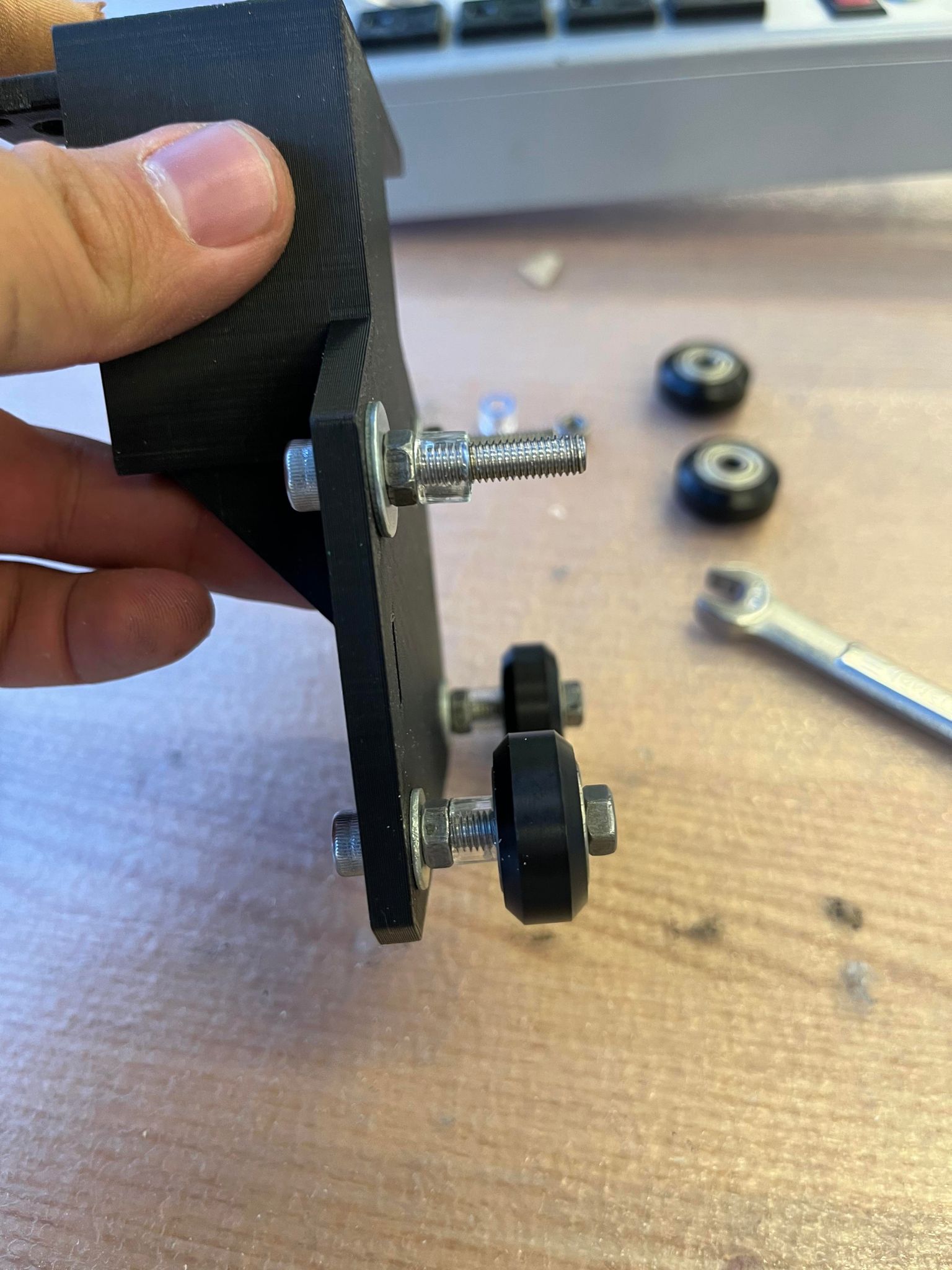
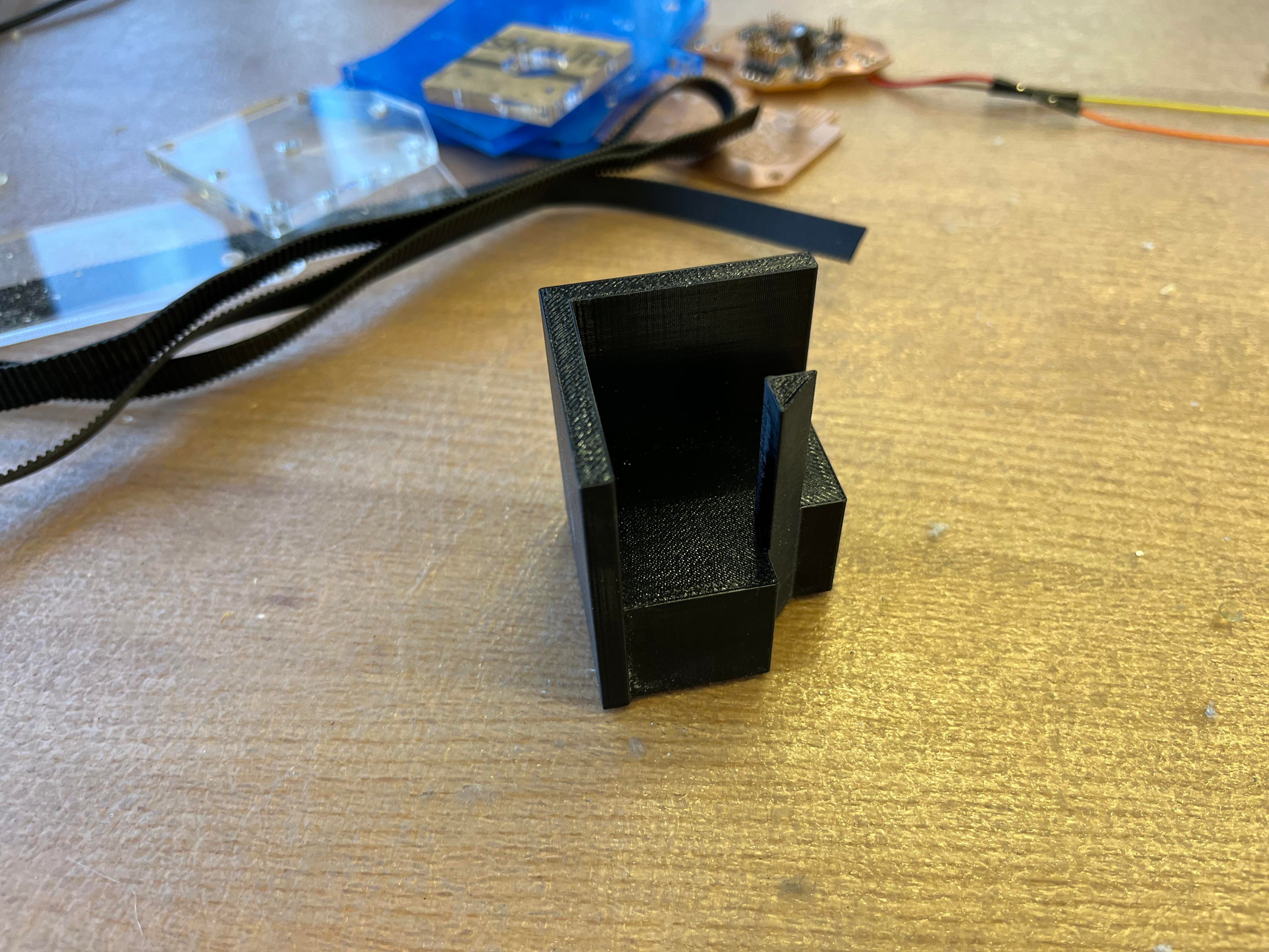
pulley mounts for rails
After puchasing the pulley, I need to make some pulley mount for my v track inspired motion systems. The issue I encountered was mainly from tolerance and width of the track. To simply put it, it was hard to figure out the width between my pulleys due to the profile of my pulley and the t-slot width of my 8020. The pulley wheels are supposed to sink into the track a bit and sandwich my 8020 fairly tight without pinching it. The solution I came up with was creating lateral wiggle room for my screws in the mounts. You can see it in the picture below. The lataral wiggle room allows me to manually tighten the wheels without printing/laser cutting trail parts. After fabricating my mounts, I need to accout of the sapce between the mount and the pulley. The easy solution I came up with was laser cutting acrylic plates to create 'washer' style spacers with through holes for M3 and M5 screws.
3D printing
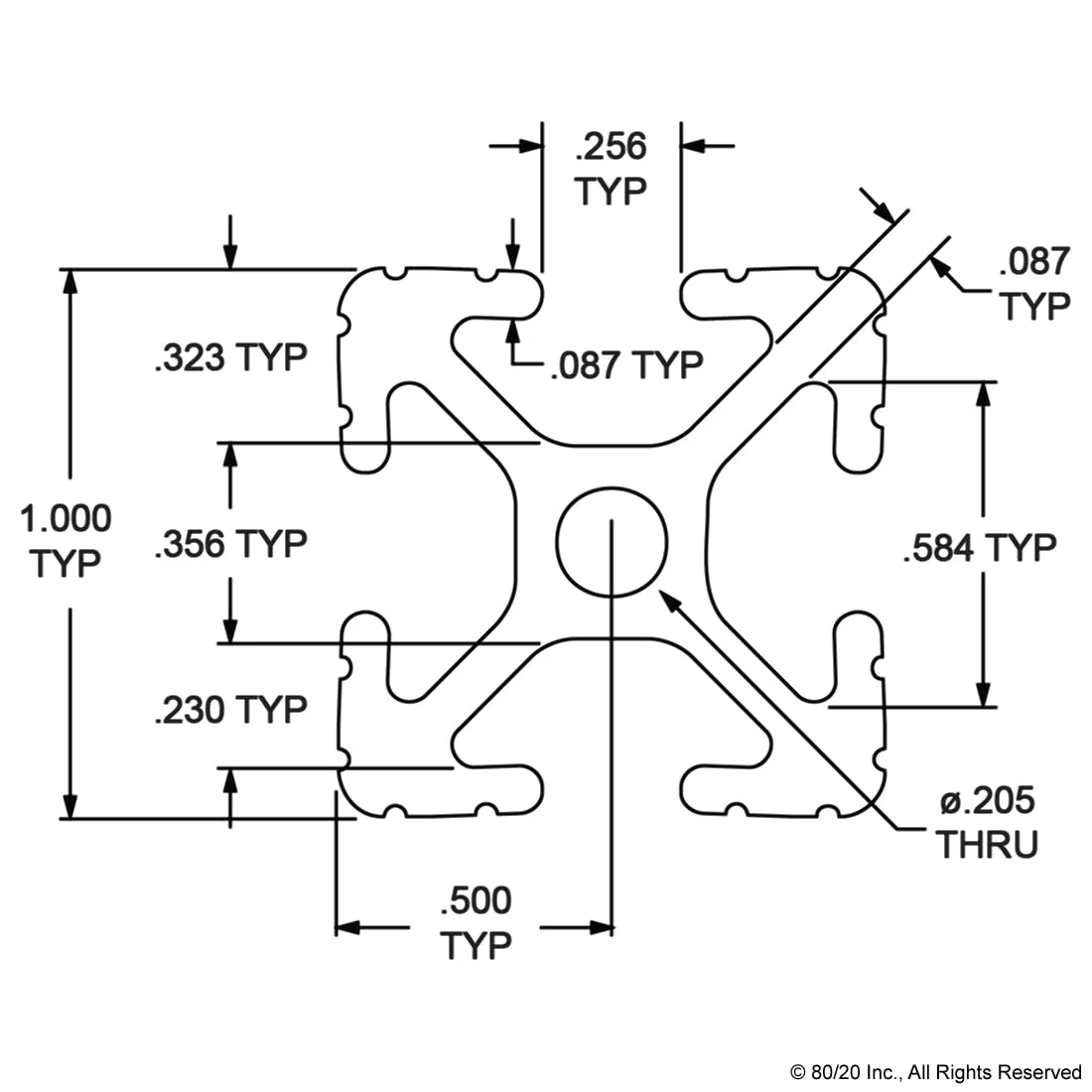
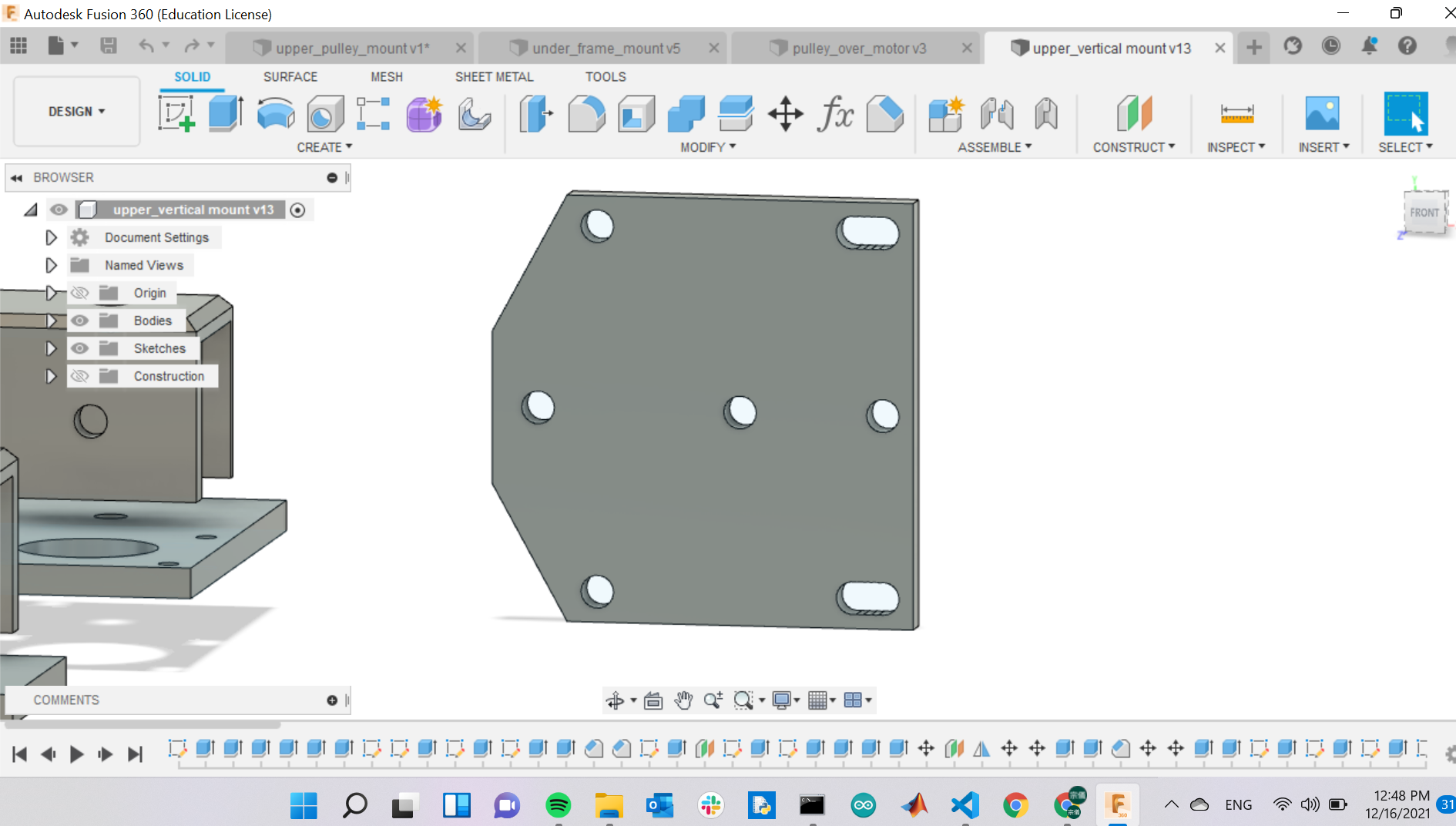
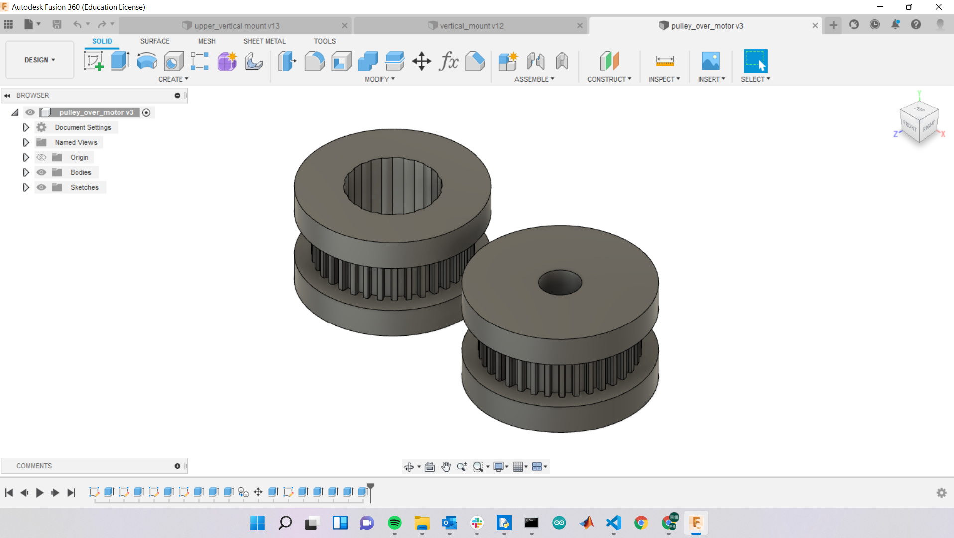
The other important part of this project is fabricating all of the mounting brackets. This part is more or less similar to making pulleys and pulley spacers. I used a combinations of laser cutting and 3D printing for most of my parts. Most of the time in this section was dedicated to measuring dimensions and make sure I can get everything into the right place. There was a minor setback in my mounting bracket for my vertical frame. I did not account of the tolerance of 8020 and had to come up with a solution. Luckily anthony jumped in and teached me how to milled down the surface of 8020 manually. I ended up milling 0.5 mm of each face of the 8020 stock and they fit perfectly afterward. It was relatively simple to design these bracket without having to think about the dimentsion of the overall machine at the time. The bottom mounting brackets are used to hold up the 8020 frame and the top mountinting brackets are used to hold the horizontal member of the vertical frame. The upper 3D printed bracket are also used to hold lead screw nuts and guide rail bearings. In addition to the mounting brackets, I also have to design and fabricate geared wheel that fit on the motors and my timing belts. I used this website to do quick geometry calculations for my bearing designs. Here are some pictures from the CAD designs:
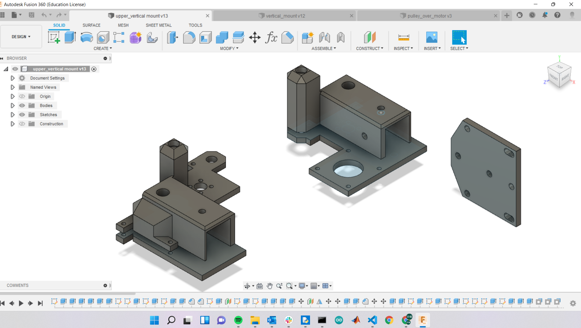
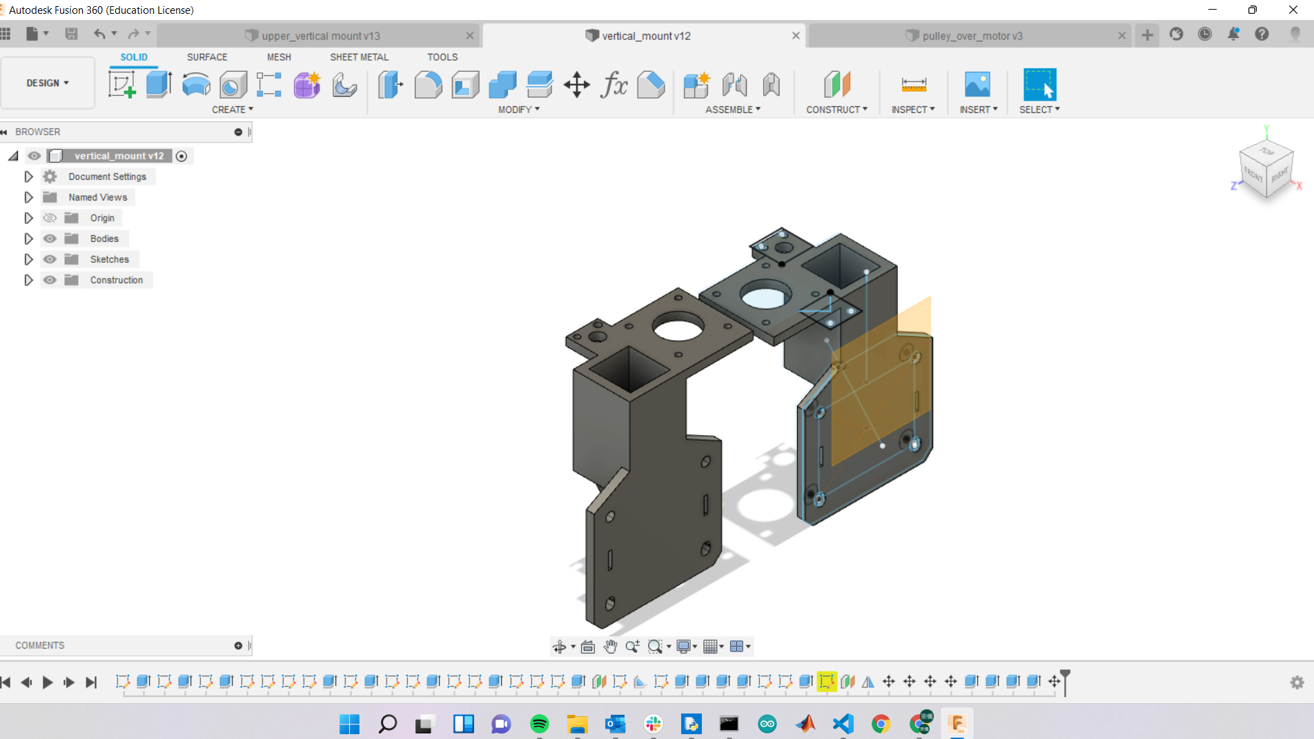
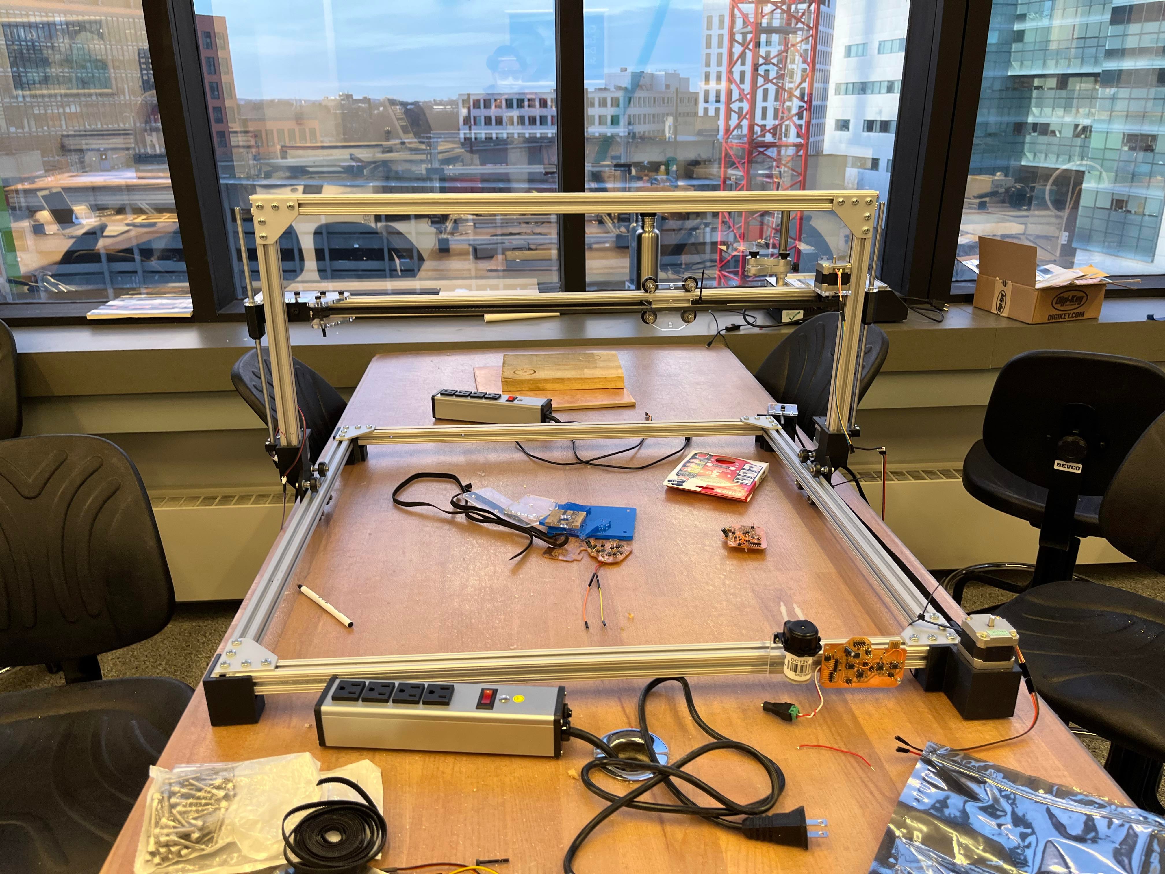
frame construction
For the frame construction, I spent minimal time on CAD and put my frame together with "wood working" mindset. The concept being I don't know the exact fit of many things on this machine, so I would cut each 8020 stock to lenght with a bit of leftover space. As I the frame together, I would press fit and cut away any leftover of my 8020 stock to achieve a tight fit while wasting minimal 8020. (Note: I was affraid of cutting all of my 8020 to size and then realize I have something loose...) I also ordered aluminium L bracket online, because 3D printed brackets were not rigid enough to hold all the weight together without shacking. You can see in the pictures:
board
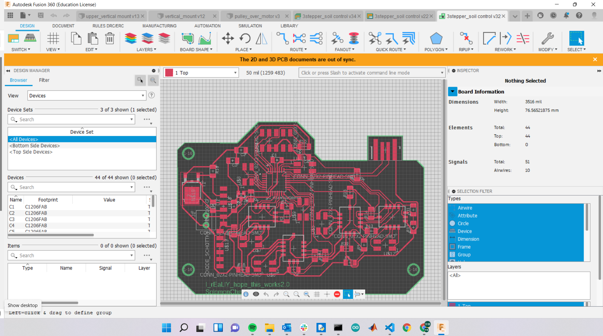
This is the relative simple part of my final project in my assumption. I could not be more wrong. Going into this part of the projec, I was confident that with my previous I/O weeks' progress, driving 4 motors was nothing but scaling up. The only possible hurdle in my mind at the time was routing PCB and the time needed for soldering. The first mistake I made was a design flaw. I placed one of my six pin header too far from the edge of the board. With a N MOSFET nearby, these pins are hard to get to and was potential shorting hazard. I tried to fix them by bending after soldering -- not a good idea at all. I end up ripping all pads of that 6 pin connector off the board and have to perform improvised board surgery with jumper wires (see in picture below). First, I hot glued the pins/pads back to the board. Secondly, I wrap solid wires individually around each pin and soilder them onto where they needed to go. This took nearly 2 hours to done right and it was no fun at all.
Afterward, I proceded to hook the board up to motor for some preliminary testing. This is when interesting things happened. The board drove all motors without problems (sadly I did not have any footage of my machine moving). However, after I deconnected my board from the motors and uploading new program, the board stopped working all of sudden. Assuming my board had some sort of failure, I started diagnosing by probing around with a multimeter. I could not find any unexpected short, ripped trace, or anything at all. To my surprise, I was measuring 5V across my 3.3V voltage regulator for my microcontroller. My first reaction was suspecting that I had grabbed the wrong power regulator since there is no obvious difference on the packages of these voltage regulators (i.e., the only difference was a letter A or B on top of the package, which was pretty much invisible to naked eyes). In the process of debugging, I made two more identical boards and tried to adjust soldering, component arrangement, and anything I could think of. I spent about 24 hrs not doing anythig but trying to debug this board. We also tried re-bootloading the board, which seemed to revive the board from time to time (depend on the phase of moon/ tide, or if I was praying to the correct diety). The board would run all motors momentarily, but after disconnection and re-connection, it would fail. This really was a mystery of that night. After remaking the board twice and confriming with Anthony that I had the correct parts, it was evident that voltage regulator or boards were not the cause of my issues. I proceeded to probe the board extensively, finding out that microcontroller pins connected to DIR (direction) pins on my drv8436 were getting 5V. This discovery led me down a rabbit hole of looking for potential cause in the drv8436 documentation. I couldn't figure out anything useful. Note, this is the Sunday night before the presentation. The conclusion was that my machine would not be able to move in my presentation since it had something to do with the motor driver. We did not have any other replacement optinos in the EECS shop at the time.
code
Even though my machine was not moving, I had writen priliminary code for controling the CNC movement already. This code is supposed to work with the Songhe capacitive sensor I bought. The intention was to create a feedback loop between soil moisture sensor and the watering system. Whenever the soil moisture content dropped below a certain level, the watering action will be triggered for targeted pot plants. I intended to optimiza movement by driving the motor alternatively, but never gotten to that point. This script also integret a serial command feedback for future user interface (i.e., basic commands can either be typed in via Arduino serial window or other controler. There is one pin that controll the MOSFET and the peristaltic pump for watering. I really wanted to include a joy stick for control, but didn't have any time). Here is the (unfinished) example:
#define DIRX 9
#define DIRY 18
#define DIRZ 23
#define STEPX 10 // PA3
#define STEPY 17
#define STEPZ 22
#define XM1 11
#define YM1
#define DIRX 9
#define DIRY 10
#define DIRZ 11
String command;
const int coef = 1;
void setup() {
  Serial.begin(9600);
  Serial.println("get to work");
  pinMode(DIRX, OUTPUT);
  pinMode(STEPX, OUTPUT);
  pinMode(XM1, OUTPUT);


  digitalWrite(DIR, HIGH);
  digitalWrite(XM1, HIGH);
}

int delayus = 10;
int changetimer = 0;

void loop() {
//  digitalWrite(STEP, HIGH);
//  delay(10);
//  delayMicroseconds(delayus);
//  Serial.println(changetimer);
//  digitalWrite(STEP, LOW);
//  delayMicroseconds(10);
  //delayMicroseconds(delayus);
//  if (changetimer == 100) {
//    delayus++;
//    if (delayus == 100) {
//      delayus = 10;
//    }
//    changetimer = 0;
//  }
//  changetimer++;
}
void box1(){
  if(command == "box1"){
    movex("forward",100);
    movez("down",100);
    movey("forward",100);
    movey("backward",100);
    movez("up",100);
    movex("backward",100);
    command = "";
  }
}
void movex(String dirx, int disx) {
  int stepx;
  if(dirx == "forward"){digitalWrite(DIRX, HIGH);}
  else{digitalWrite(DIRX,LOW);}
  stepx = disx*coef;
  for (int i = 0; i <= stepx; i++) {
    digitalWrite(STEPX, HIGH);
    delayMicroseconds(delayus);
    digitalWrite(STEPX,LOW);
    delayMicroseconds(delayus);
  }
}
void movey(String diry, int disy) {
  int stepy;
  if(diry == "forward"){digitalWrite(DIRY, HIGH);}
  else{digitalWrite(DIRY,LOW);}
  stepy = disy*coef;
  for (int i = 0; i <= stepy; i++) {
    digitalWrite(STEPY, HIGH);
    delayMicroseconds(delayus);
    digitalWrite(STEPY,LOW);
    delayMicroseconds(delayus);
  }
}
void movez(String dirz, int disz) {
  int stepz;
  if(dirz == "up"){digitalWrite(DIRZ, HIGH);}
  else{digitalWrite(DIRZ,LOW);}
  stepz = disz*coef;
  for (int i = 0; i <= stepz; i++) {
    digitalWrite(STEPZ, HIGH);
    delayMicroseconds(delayus);
    digitalWrite(STEPZ,LOW);
    delayMicroseconds(delayus);
  }
}
Big reveal(what was wrong)
At my presentation, Zach explained that the first version ("moo")of the stepper motor driver had a design flaw. He was forced to short the Nsleep pin to the VRef pin (which was connected to the VDD of microcontroller on my board ). Nsleep pin was connected to the internal 5V power regulate on the drv8436, which backs up voltage to my microcontroller. I have gotten the revised version of the drv8436 and plan on fixing my machine as soon as I can. Sadly, I am flying out for holidays and don't have time to complete this within the week after presentation. You can see the little piece of wire on the drv8436 module in the microscope picture below.
I have updated my board designs and will be doing electronic productions soon to make my machine move! There are now three pines on the bottom of Zach's drv8436 modules. He fixed it by breaking out the Nsleep pin. The updated board design is listed below with all other CAD designs, but here is a picture of what it looks like:
Current state of the machine
It is missing a functional board. I still need to mill a functional board for it and make sure all motor are driven correctly. But other than that, all of the mechanical designs and assembly were completed.
Links to CAD designs
Farm body
Farm body, parts that don't fit onto 4'x4' sheet OSB
assembly video of the farm body (press fit)
under frame motor mount, under frame pulley mount,
under frame mount (right), under frame mount (left)
vertical mounts for 8020 (need to expend 1mm for tolerance
upper horizontal v track pulley mount
cap of the horizontal 8020 on the vertical (left), (right)
board and pump mount
final board design (fixed drv8436 issues)
drv8436 breakout footprint lbr for Eagle/fusion
Note:
This project was inspired by FarmBot