Networking and Communications
The assignment for this week was: design, build, and connect wired or wireless node(s) with network or bus addresses.
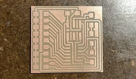
[1] Board Design & Fabrication
This week I was able to make a good amount of progress towards my final project, the car dashboard. On the dashboard, there will be both digital screens and analog gauges for displaying information, and rather than having one central processor control everything, I decided to give each display interface its own microcontroller and chain them all together using I2C. Therefore, it made sense this week to figure out how the I2C implementation would work. Considering that I had made a test board with the gauge stepper motor during the previous week, this week I chose to start working on the digital screen part. I designed two different boards this week: one that controls 9 LEDs, and another that controls a 128x64 OLED screen; both of them will be communicating over I2C. This week, I also switched over from the outdated ATMega328P chip that I was previously using to the newer ATTiny1624, which was much simpler to use -- 1 wire programming interface, no external clock required to run at 20MHz (unlike the ATMega), and wider pin spacing to allow for easier board milling and soldering. These are what the two different boards look like:
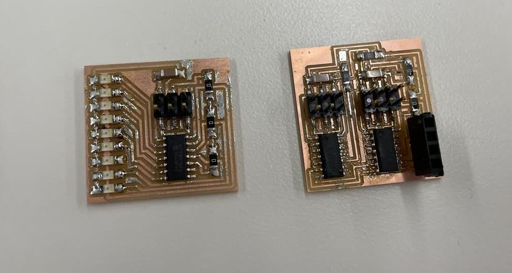
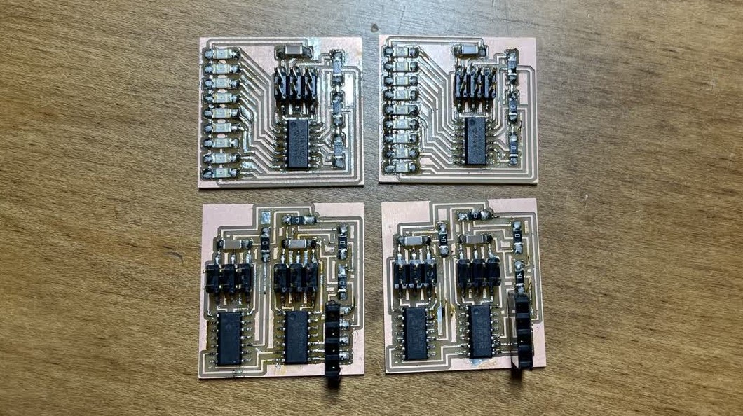
One thing of note is that the OLED screen board has two ATTiny1624 processors on it. This is because I needed to solve the issue with shared I2C addresses: the OLED screens I am using can be configured to use two different I2C addresses -- 0x3C and 0x3D -- but no more, which is an issue since I plan on using five such screens in my final project. I solved this by using two processors in a way so that one processor is connected to the main I2C bus and can be configured to use an I2C address via software, and then it forwards whatever data it receives from the main I2C bus over serial (UART) to the second processor. The second processor then interprets that data and displays it on the OLED screen connected to its I2C bus. That way, multiple OLED screens can be used, each effectively having its own configurable I2C address. I ended up making 4 boards this week; 2 of the LED boards and 2 of the OLED boards:
[2] I2C Bus Connection
Now that I had my individual boards, I created a cable using IDC connectors and ribbon cable to connect everything together, along with an additional place to plug in power input to the entire I2C network as well as the important I2C pull-up resistors on the SDA and SCL lines. This is what the set up looks like without the OLED screens plugged in:
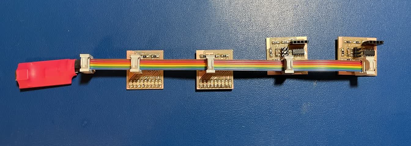
and with the OLED screens plugged in:
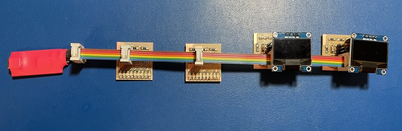
I programmed the leftmost board to send out a continually incrementing sequence of numbers to the other three boards. The first board (the one with 9 LEDs) displays whatever number it receives in binary, and the two OLED boards both display their received numbers on the screen using a font that I drew by hand. Each of the boards receiving data joins the I2C bus with a unique pre-determined address (here I just used 1, 2, 3) whereas the master controller does not need to join with an address since it never needs to receive data from other devices. Here is a quick video of the entire system working: