Electronics Design
This week's assignment: redraw an echo hello-world board, add (at least) a button and LED (with current-limiting resistor), check the design rules, make it, and test that it can communicate.
[1] Schematic and PCB Design
Before getting started this week, we took part in the group assignment where we learned about testing and debugging boards with test equipment such as oscilloscopes and multimeters. What we learned is documented here.
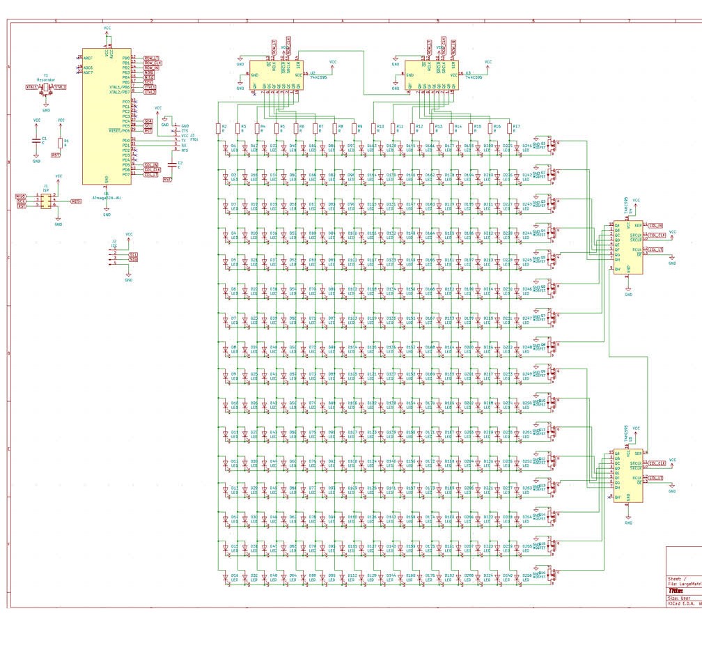
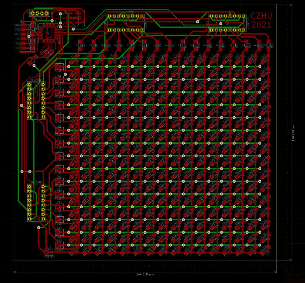
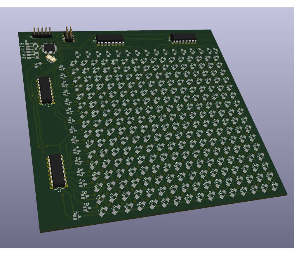
For this week's assignment, I decided to take a more adventurous spin on what was required. Rather than have just a single LED on my board, I wanted to create a board with a 16x16 grid of LEDs -- yes, 256 LEDs in total (that I had to painfully solder one by one). In order to drive this many LEDs, I had to use shift registers, specifically the (in)famous 74HC595 SIPO shift register. The SIPO means Serial-In, Parallel-Out: a microcontroller can send serial data over 1 pin to control 8 pins of the shift register in parallel. To drive the shift registers, I went with the ATMega328P microcontroller, the same one used in the Arduino Uno. Using KiCad and a solid chunk of time, I was able to design the schematic and a corresponding 2-layer PCB for this LED matrix. This is what the schematic, PCB, and 3D rendering of the LED matrix board look like:
[2] PCB Milling
After exporting the SVGs of the front traces, back traces, vias, and board outline from KiCad, I manually aligned them in Inkscape and exported them as four separate PNG files at 1000 dpi. Using mods, I then milled out the PCB. Because I was milling a board with such a large area, I had to increase the cut depth for certain parts of the front and back traces files in order to mill out all the traces correctly. This process took painstakingly long: I had to mill out the traces in one pass, see which areas were not fully cut through, adjust the PNG file to remove all the areas where the traces did cut correctly, remill the new PNG file, and repeat this process until everything was cut through. After this grueling process, I did end up with a nice-looking board though! Shown below is the board while being milled, and after the milling was complete.
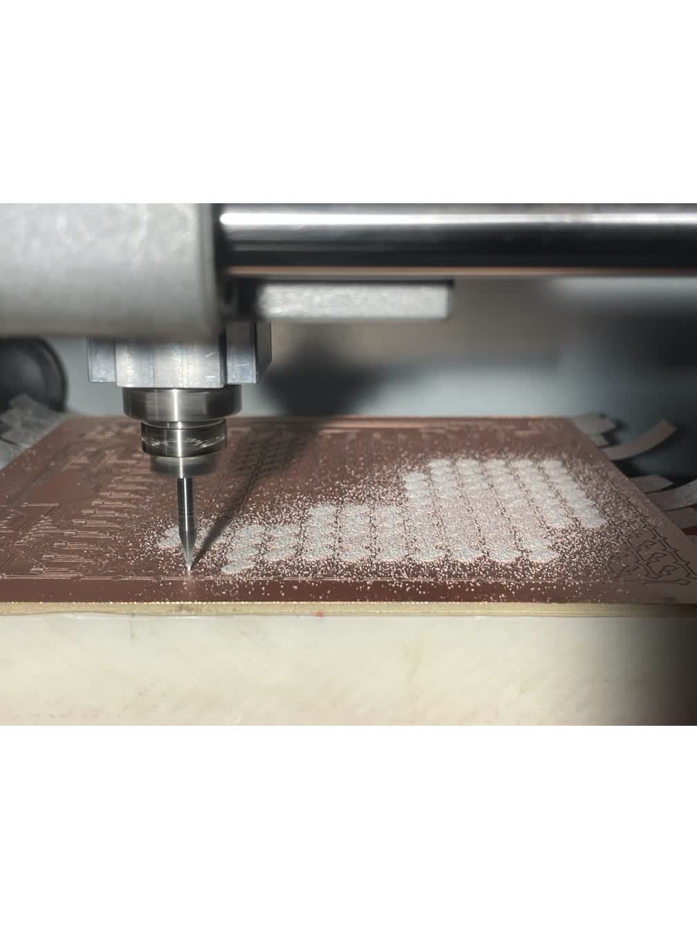
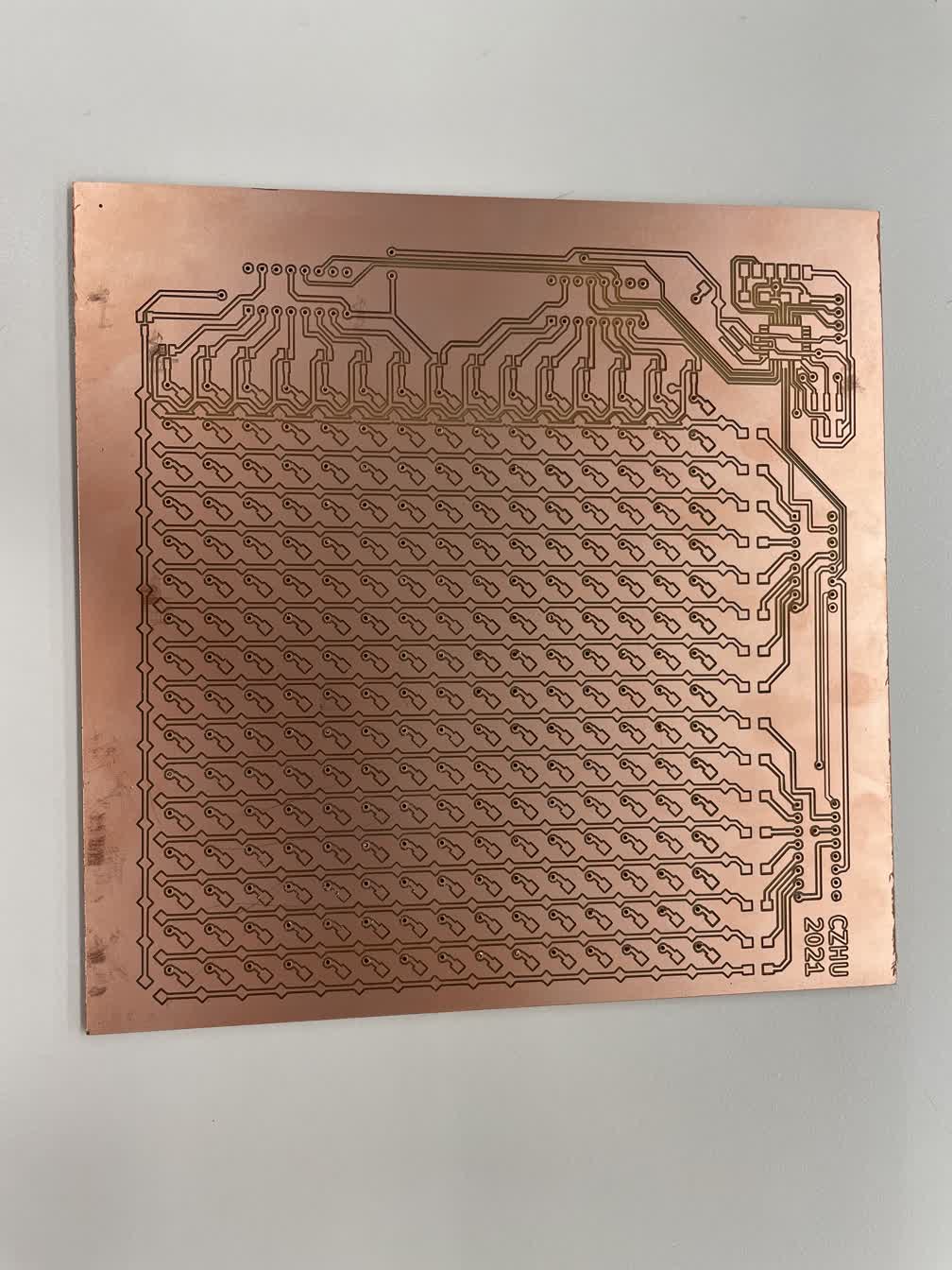
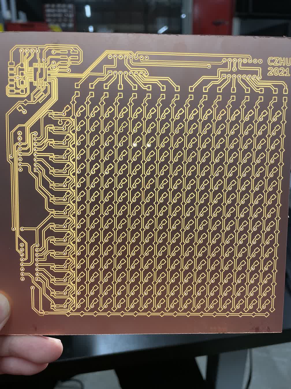
One of the most satisfying moments was holding the finished board up to a bright light and seeing that all of the traces were milled out properly:
[3] Populating the PCB
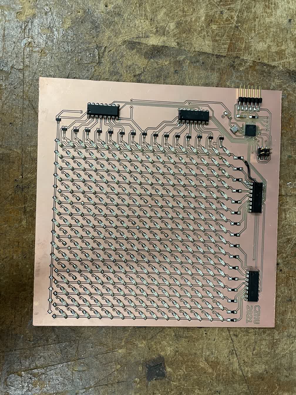
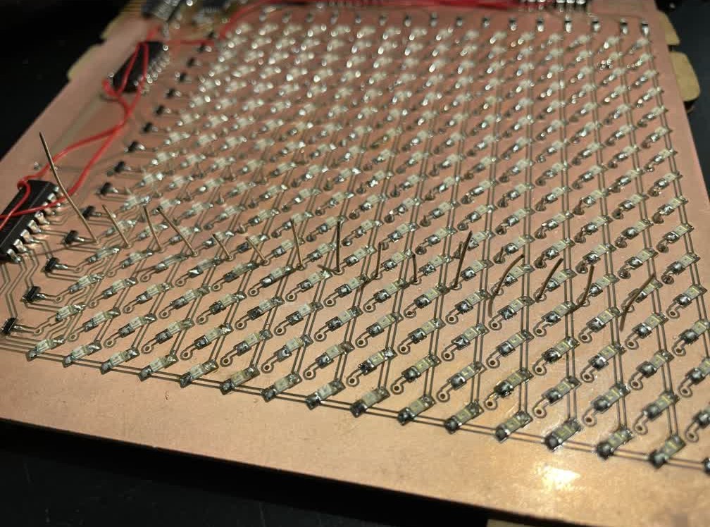
After what seemed like the worst part of the process was over, I now began soldering components to the board. In short, this was a pain: 256 individual LEDs really does take a long time to solder. Moreover, I had to "debug" my soldering, since there were a not-insignificant amount of smaller solder bridges I had to find one by one using a multimeter. Better yet, since there was no double-sided board stock available in the Harvard shop that day, I was not able to mill out the back traces of the board. Instead, I had to painstakingly solder bodge wires to act as the traces that would have been on the back of the PCB. Speaking of double-sided boards, instead of being able to use copper rivets as vias, I had to insert small pieces of wire through the via holes and solder them together on the back. This is because the lack of traces on the back meant there were no spots for copper rivet vias to connect to. Overall, I would absolutely not recommend this process to anyone ever, but fortunately the results were worth it -- check out the results from week 6 and week 8 to see how beautifully everything came together!
This is what the board looked like after soldering all of the components on the front:
After soldering in the wires which were meant to be traces on the back of the board:
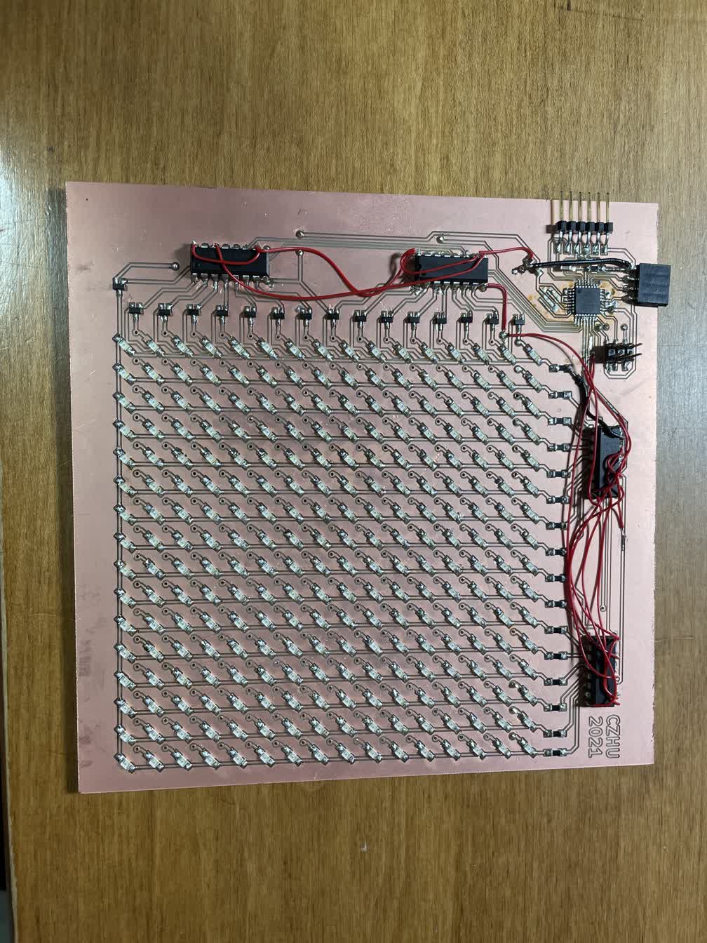
Inserting small pieces of wire in the via holes:
In the end, I was able to load a simple serial echo program onto the ATMega328P and confirmed that the board indeed works. For more in-depth software and actual usage of the LEDs in the matrix, check out the results from week 6 and week 8!