Output Devices
The assignment for this week was: add an output device to a microcontroller board you've designed, and program it to do something.
[1] Schematic and PCB Design
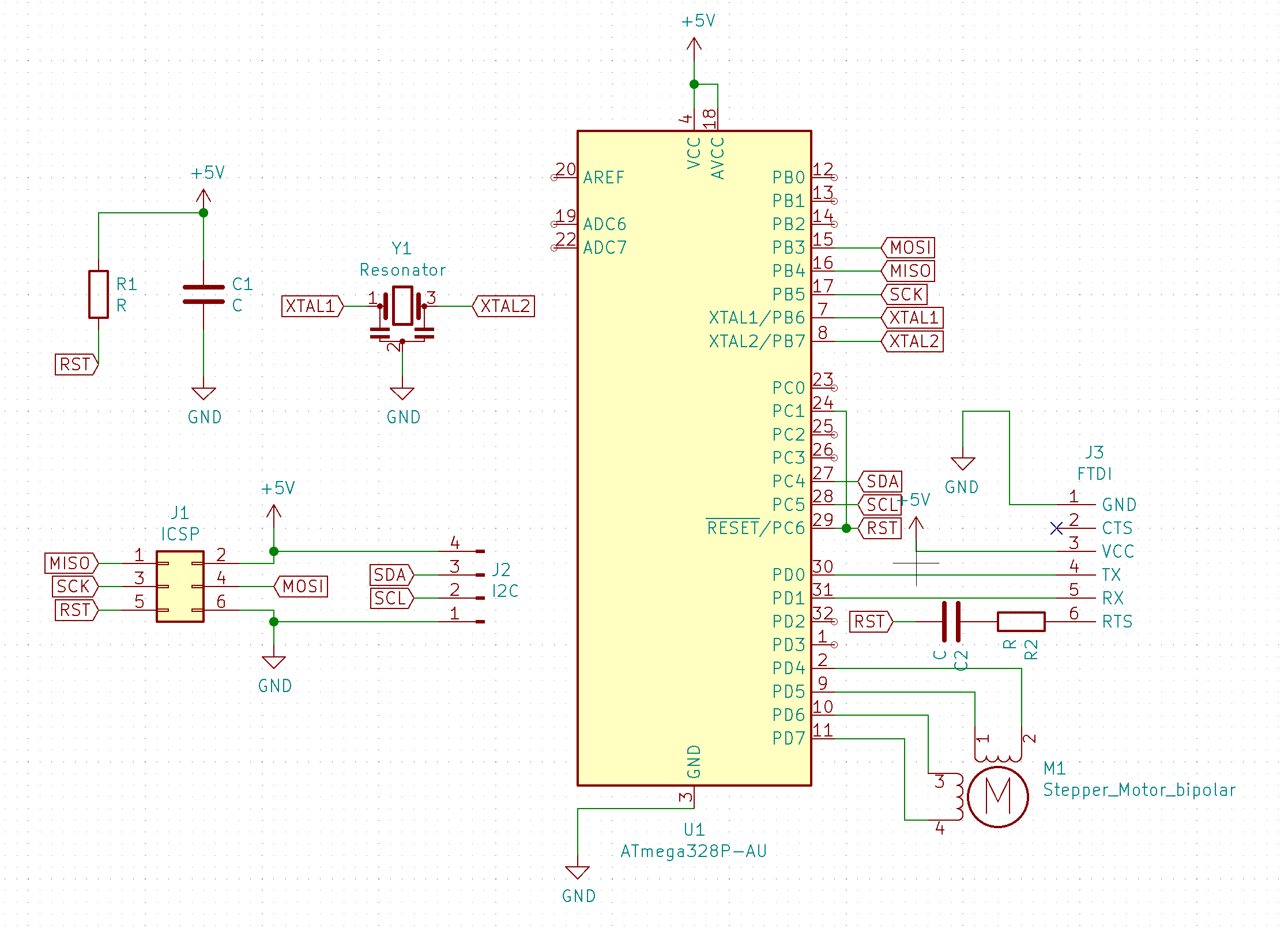
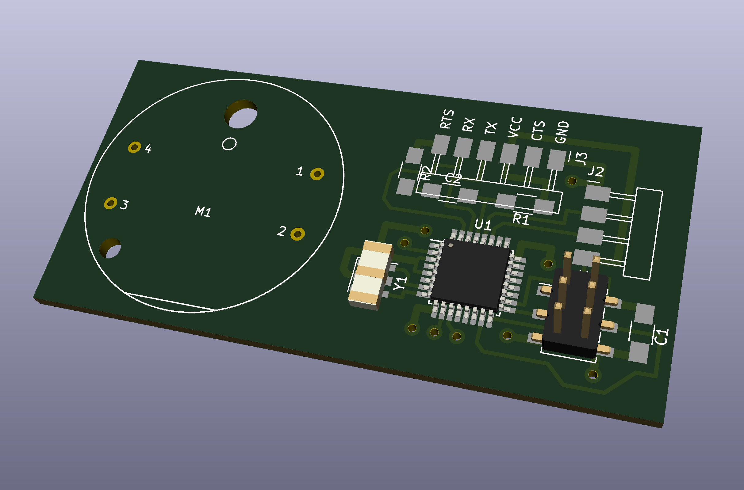
Technically, I could just paste in my page from week 8 and call it a day here since the LED matrix is an output device. But, during this week I changed my final project idea (see final project tracking page), so I decided to get working on that in some part. Since I was now planning on creating a dashboard for a car, it was a good idea this week to figure out how to create a working analog gauge. I designed a simple circuit using at ATMega328P around the X27.168 stepper motor, a small low-power stepper motor used in dashboard gauges of many production vehicles. The interesting thing about this stepper motor is that because it draws such low current (around 20mA, due to a high phase resistance), it can be driven directly from the pins of a microcontroller. In fact, as part of this week's group assignment, I measured the current consumption of this small motor: at full speed, it consumes an average of 16mA at 5V, and when stationary and holding its position, it consumes around 8mA at 5V. This means that the circuitry required to control these motors is extremely simple, and there is no need for a dedicated stepper driver IC and separate motor power supply. Here are the schematic, PCB, and 3D rendering of the test board I designed:
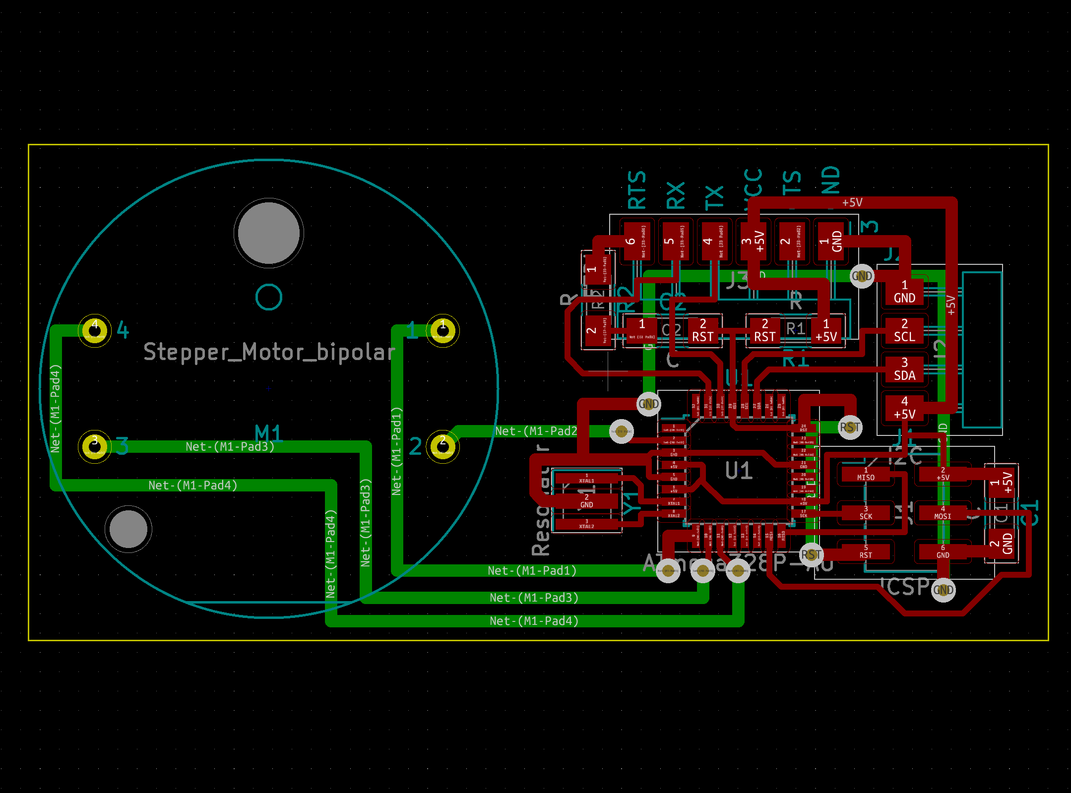
Because the motor I was using is a non-standard part, I need to create a custom footprint for it in KiCad. Fortunately, someone else had already done this and their work was on GitHub, so I was able to use their .kicad_mod file for the gauge stepper motor.
[2] Assembly
After milling the board, I soldered on the components and tested it. This is what the board looked like with everything except for the motor soldered on:
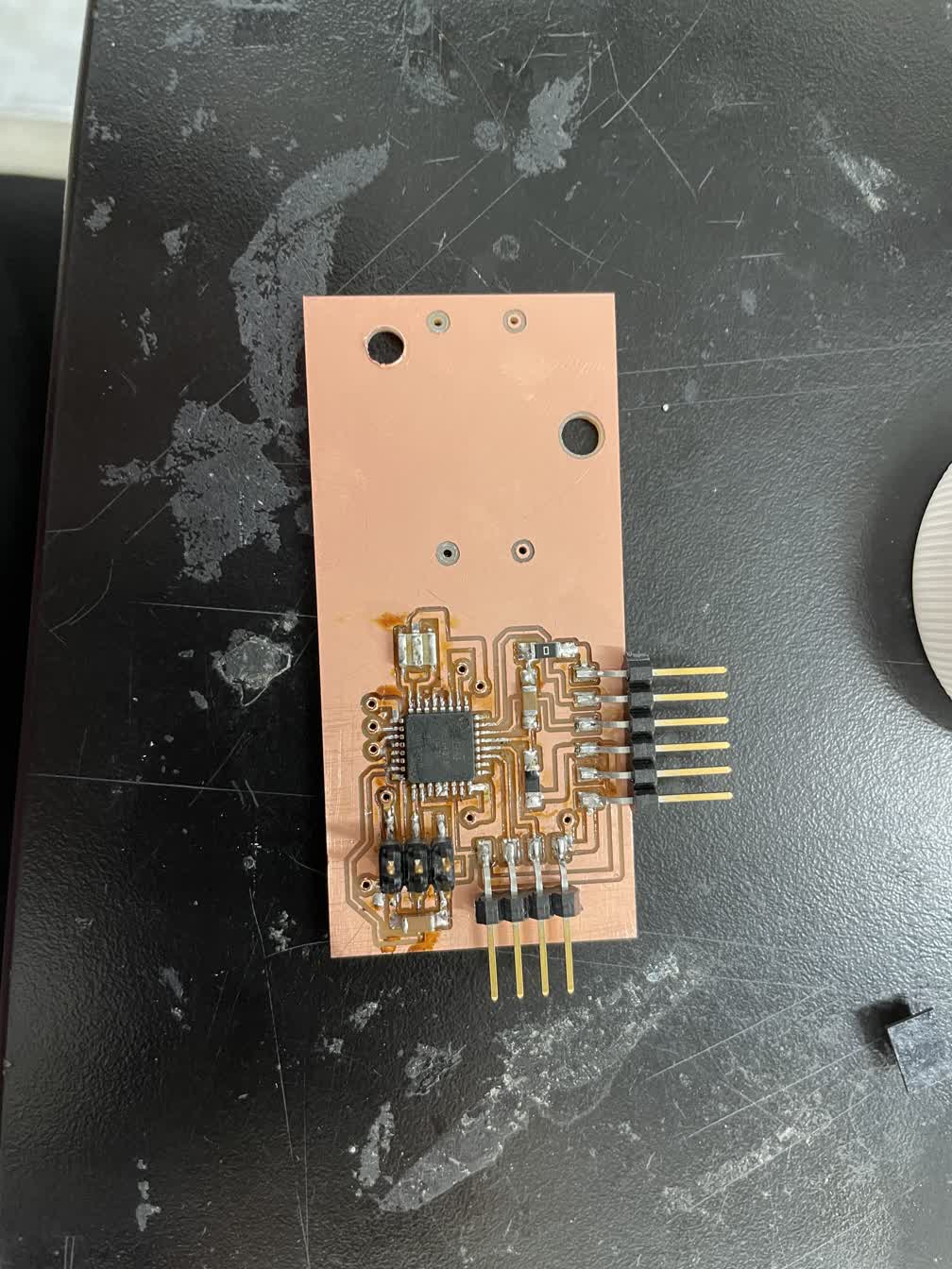
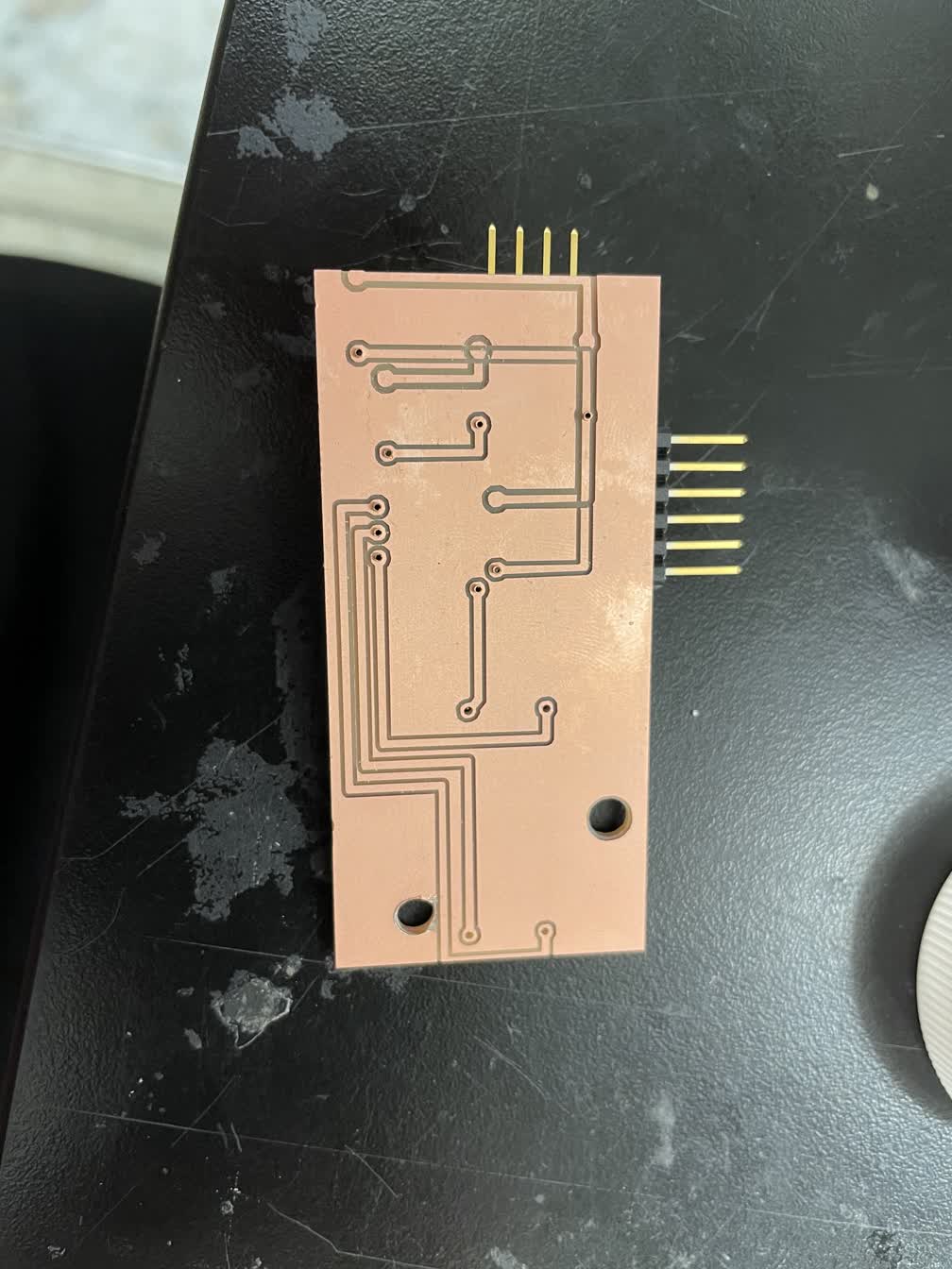
As seen in the image of the back of the board, I had a small alignment error when I tried milling the traces on the back, but I managed to stop the mill before things got too out of hand. After remilling the back traces correctly, I only had to solder in two small wires to fix the incorrect traces.
I finally uploaded a small piece of test code to verify that the motor works: