
My original plan this week was to build an outdoor shed for my bike. But after some internet research I learned that I’d need a minimum size of 6’ x 4’ x 2’ to fit my bike, which is 76 square feet, without a floor. That’s more than two 4x8s (64 ft^2), so I decided it was too ambitious.
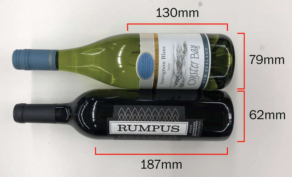
So I pivoted to ... a wine rack! I think I’m one of several wine racks this week. There are a lot of different wine bottle shapes in the world, so I decided to optimize for a standard red and a standard white. Based on my measurements, I decided I needed that the wine bottles should rest in 85mm curves (to give me wiggle room), and these curves should have a 100mm gap.
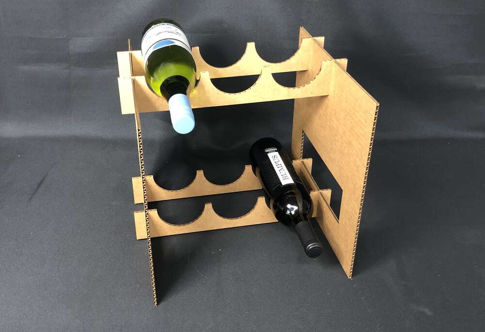
Since this is a rapid prototyping class, I figured out start out by designing a cardboard version. To keep it simple, I decided to make everything simple slot joints. They’re pretty deep, deep enough so that the cross pieces should be flush with the side pieces. (I think this is called a “halved joint.”) This is parameterized so it would be simple to swap in for plywood once I get there.
Back in Week 2we used a program called LightBurn to run our files for the laser cutter. But our trial version had run out, so I had to switch over RDWorksV8, which worked fine. The two issues I ran into were that RDWorksV8 wasn’t aware of how large my pieces were (I had to scale them up) and I learned that DXF files aren’t aware that construction lines aren't real. Both easily solvable, and my wine rack came out great with nice joints.
This was pretty small, and I wanted to end up somewhere “meter scale,” while also keeping in mind how large of a wine rack I’d realistically need. I decided to expand it to a ten-bottle rock.
I was about a half-day behind my sectionmates for a lot of the week, which was great because I could learn a lot from them. Rosalie reminded me to fillet my slot joints, and told me that (thank god) it wouldn’t be 100% necessary to add a dogbone.
I’d been trying to add dogbones by hand – the tutorial that got sent around to the group was for inside edges of a 3D model, and I was doing everything in sketch mode. I found this nice guide and the math worked out, but it was pretty tedious and once I started trimming I was having a lot of trouble keeping my designs constrained. So it was nice to be able to ignore dogbones, instead I just added 1.5mm to my joint depth to make up for the curves. My joint width was simply the material width.
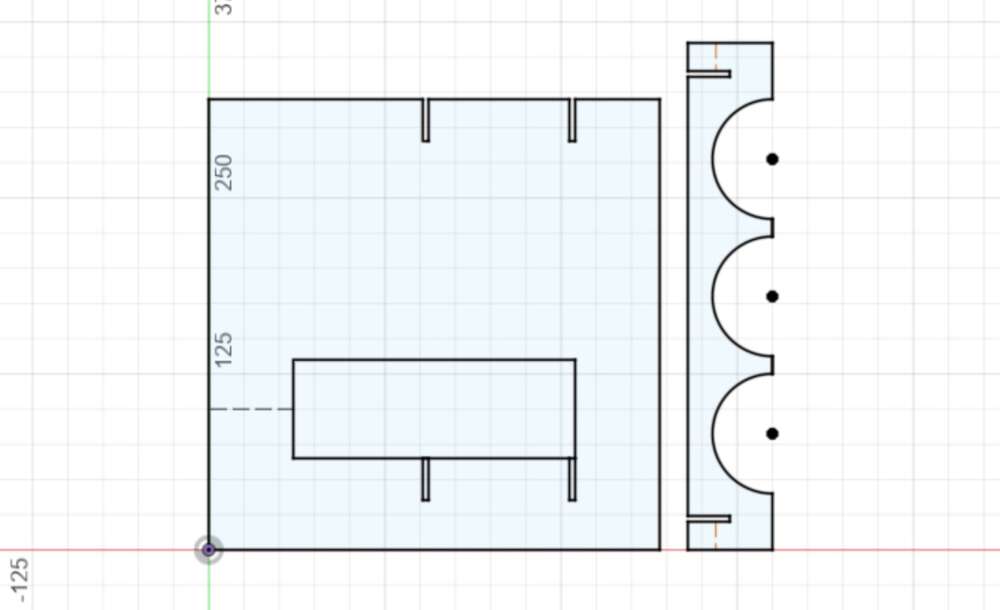
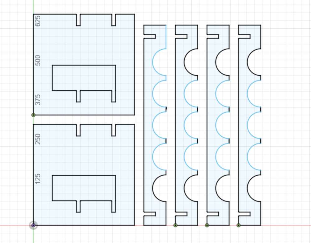
As I got closer to wrapping up, Doria gave me a tip that my overhang (the part of the crosses that extends beyond the side piece) should be a little longer, or else I’d risk having the brittle OSB snap offf. So I made that change. Here was my final design. Note that this screenshot is after I removed my construction lines to clean up the DXF file, which (mostly) explains why my piece isn’t totally constrained.
I brought this design into Aspire to build my cut paths, and ran into all sorts of problems with joins. Even though Fusion recognized that I’d built a series of closed shapes, Aspire did not, and just saw a bunch of segments. I cleaned up my contruction lines and reimported, and it threw fewer errors and let me advance, and so I thought I was good to go.
I made sure my design had tabs, although I made the mistake of autogenerating them first, which creates about 1000 tabs. So I spent a while deleting a bunch of them.
On Monday night it was my turn for the shop bot. But when we did the air cut, it was clear that something was funky – it was still cutting everything as individual segments
Me and my TA Nathan went upstairs to check it out in Rhino. We were able to join most segments, and figure out the culprit for why some other segments were acting weird – I had duplicated some of the circles in my crosspieces. After we deleted those, it was a snap to join my design into eight closed shapes.
We also noticed another problem – I was cutting everything in one layer, but my design has interior “windows” in the side pieces that needed to be cut on the inside edge instead of the outside. So I made two layers. I also added my tabs by hand instead of automating them, which was way faster.
With those changes, my file was good to go, and I’d only burned half of my hour-long slot with the machine. Here’s my shop bot cooking. All and all the cutting took a little under 30 min, and the only scare was that my 20mm x 20mm offset probably could have been a little larger, I was quite close to the edge.
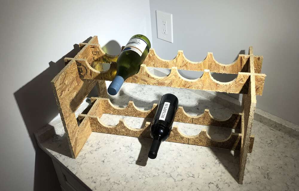
I pried my pieces off and everything had cut great, or at least as great as OSB can cut.
I assembled the wine rack, and even without dogbones my cross pieces were basically flush. Some of joints were really snug (not too snug, just right) and some of them were slightly looser. Not sure what could have caused that difference but my final shape is solid nonetheless. I was inspired by this week’s recitation to try a fancier picture, although I don’t have a backdrop.
Ta da! Now I just need to buy more wine.
This week I also took the safety training to use the ShopBot, which was part of the group assignment. As a section we didn’t test all of the characteristics of our machine (like I’m not sure we tested any other materials) but we did create a test cut to get a sense of what sort of tolerances we could get away with for our joints.
This is what led me to make my joint width simply the material width, and that worked fine. In part because my joints were slot, so I kind of only had to worry about the tolerances on one axis instead of two, which is different than a butt joint.
I was involved in group work in a different, important way this week. I helped shuttle people’s big things for show and tell!
Files: Here are the final DXF files for my cardboard and OSB versions of my rack, plus the SBP code that I sent to the machine.