
My first order of business this week was to make a breakout board, as many others have done. Basically, a simple arduino-like device that will let me hook up various peripherals for input/output/network testing. I’m going to base it around the ATTiny412 and call it “Reubino.”
The class has mostly migrated to DC11s. But I’m sticking with my Tinys! For a few reasons.
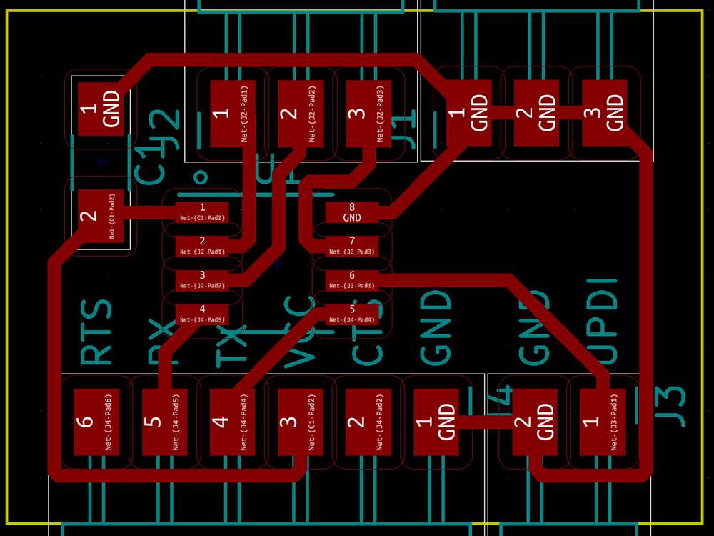
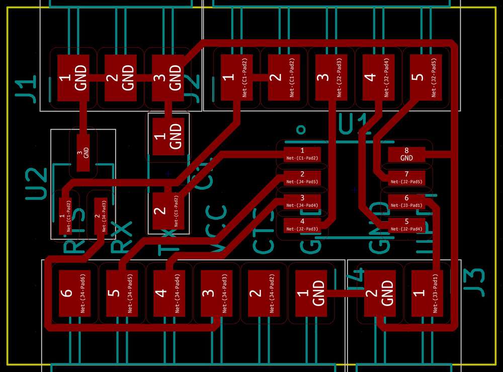
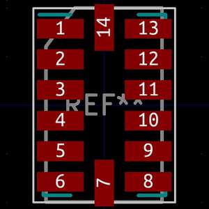
I put together my Reubino design with FTDI and UPDI connectors, which left me with three exposed pins. (Eight to start, minus GND, VCC, UDPI and an RX and TX pin for FTDI.) Was pretty pleased with my layout.
The input I’m going for this week is a three-access accelerometer, the ADXL343. For my final project, I’m hoping to use a six-axis accelerometer to track the path of a ball thrown in the air, so I figured this was a nice way to get started.
However, looking at the accelerometer example board I realized that my Reubino design was missing a piece: I’d also need to expose VCC. On Sunday night I had a nice chat with Rob who pointed out a couple other tweaks I needed to make.
(Rob also answered a dumb question of mine. I was wondering if it was safe to expose VCC as male pin headers. Like, could someone get shocked if they touched it? But the currents we’re working with aren’t even close to strong enough for that.)
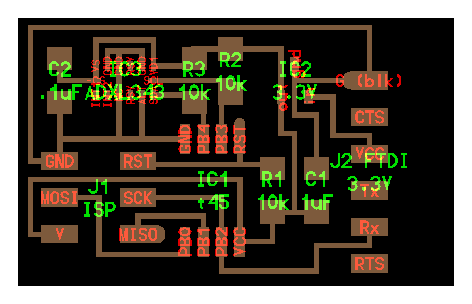
I decided to expose two VCC pins in case another peripheral needed a power line, and also because it gave me really nice symmetry on my breakboard board. With those tweaks made, here was my final Reubino design. Compact with no jump resistors!
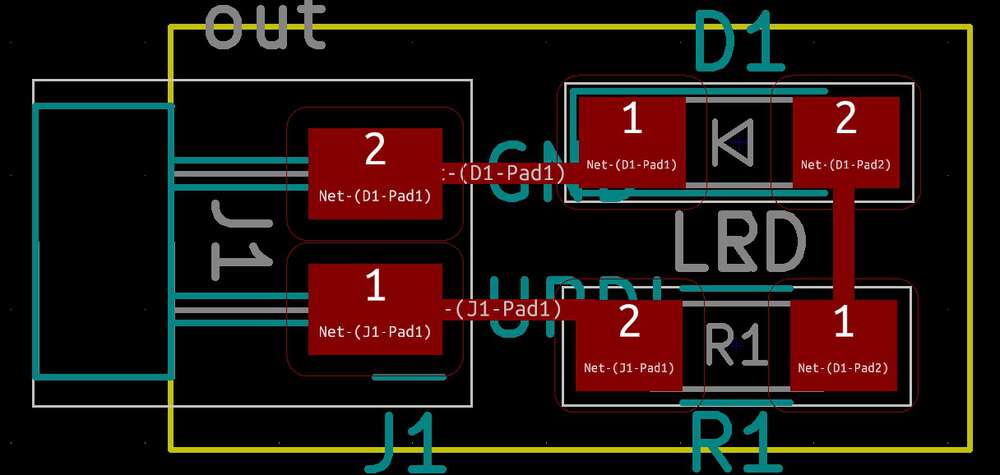
I then decided to design two peripherals: One containing a three-axis accelerometer and one with a simple LED for blinky testing. The blinky peripheral was a breeze, here’s the final design.
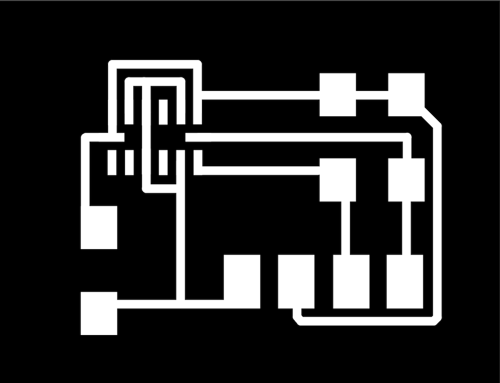
The accelerometer, based on the t45 example for the ADXL343, was a lot tricker. The default accelerometer pads are actually too wide to allow for the 0.4mm minimum clearance for the 1/64 end mill. And they’re too close to each other for KiCad to let you draw 0.4mm traces.
The solution: I dropped the traces down to 0.25mm so I could draw them in Kicad. And then in Adobe Illustrator, I increased the size of the traces and narrowed the size of the pads so that everything was 0.4mm wide with 0.4mm gaps. This seemed to match what Neil did for his example. Here’s where I ended up, after my Illustrator edits.
Then it was time to cut my boards. It’s nice to feel like I’m getting better in this class, and for the first time milling went very smoothly for me. Here’s the whole gang. I cut an extra breakout and accel.
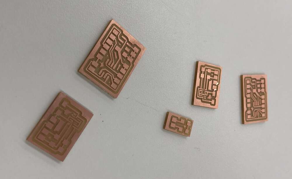
I was freaked that I wasn’t going to have handled the accelerometer pads correctly, so I was thrilled when I saw how clean they milled! Although the pads are so tiny that one of them peeled off on one of my boards. (Luckily, the pad wasn’t used for anything.)
Because of a design mistake, I did get two paths merged on the Reubino. But these were both VCC lines coming from the capacitor, so I don’t think that this is actually a problem. It should have just been one line in the first place. (Nathan confirmed that this was fine.)
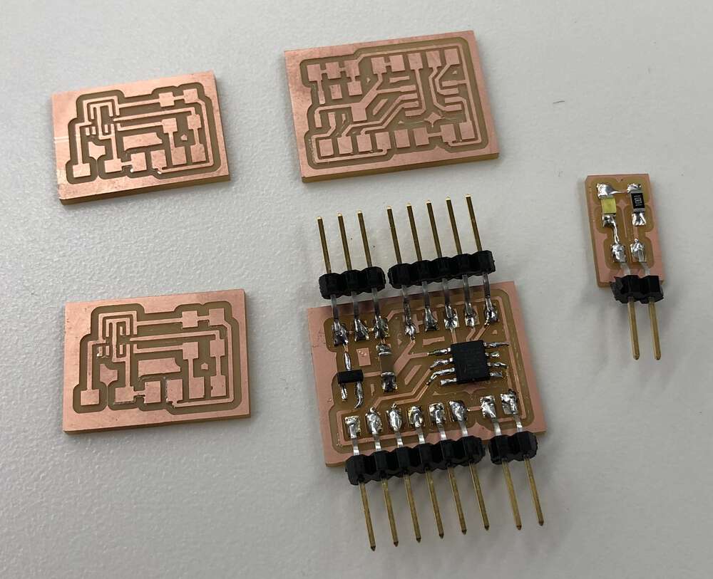
Then it was time to stuff. I started with the Reubino and the blinky peripheral. With the exception of one coldish solder on my ATTiny microcontroller (keeping an eye on pin 4!), I’m very happy with how stuffing went.
I’m still not fast, but I took Neil’s advice from when I presented in class a couple weeks ago, and kept my iron on for just a little longer after the solder started flowing. I didn’t nail everything but this left me with a good number of shiny/smooth joints, and it actually felt like my solder was “wicking up” the pads of my components.
I was starting to think about how to solder my accelerometer peripheral, which was going to involve reflow since the pads are on the botton. But then Chris Zhu became my hero of the week. He told me that we had a different three-axis accelerometer in stock in our lab (the LIS3DH) that already lived in its own breakout board.
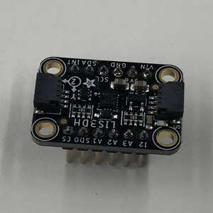
Just like the ADXL343, it could communicate through IC2 so my Reubino was all set up to handle it. I snagged one of them and saved myself the trouble of having to learn reflow this week.
This meant that I was ready to start testing and programming, but there was a problem. When we did embedded programming a few weeks ago, we had a nice USB-to-UPDI adapter in our lab. But it was nowhere to be found! And the other UPDI programmers didn’t seem to be working correctly, or at least we couldn’t figure out what resistor they were missing. They would all throw UPDI initialziation errors.
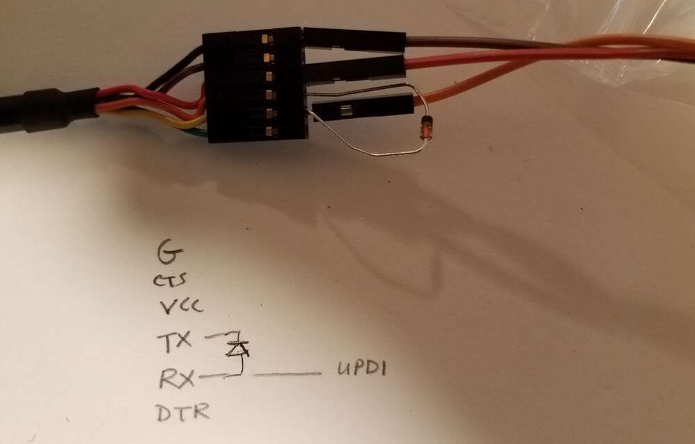
Rob came through with a lovely diagram of a hack that turns an FTDI connector into a UDPI programmer. You jam a diode into RX, running to TX. Which turns RX into UDPI.
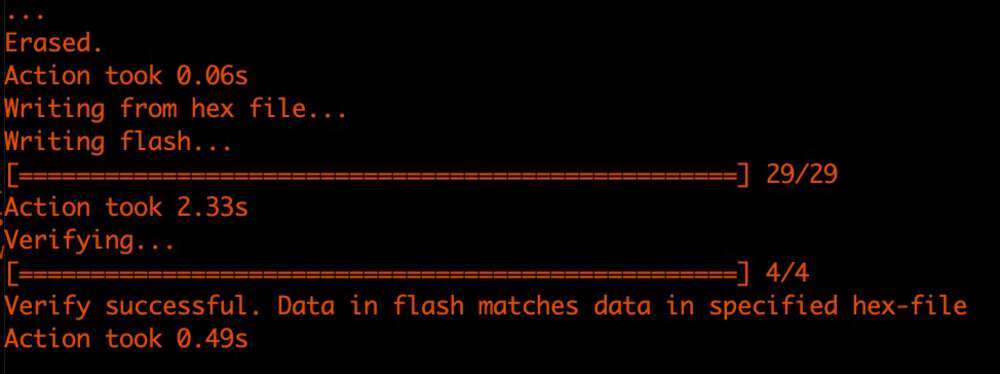
I’m not going to lie, this setup felt incredibly janky. So I was shocked when it worked great.
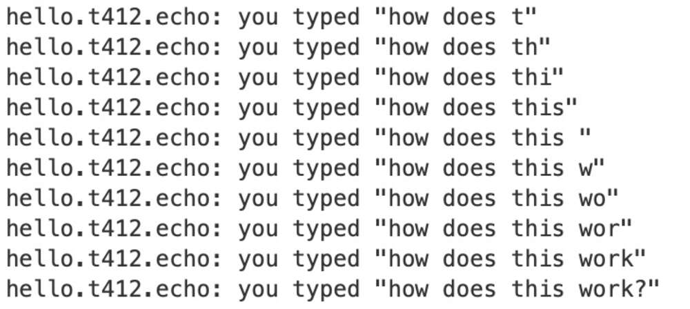
My Reubino doesn’t have a light on it, but it does have UDPI and FTDI, which means I can test echo to make sure it’s working correctly. But I uploaded echo.ino and my Serial terminal was empty. Was my Reubino a dud???
But then I remembered that Neil’s echo script for the Tiny412 used the alternate RX and TX, while my board did not. So I just had to delete the Serial.swap() line from the code. And then it worked great.
Then it was time to test my first peripheral. I plugged my blink board into ground and port 4, because I wanted to see if that potential cold solder was in fact a problem. I pushed the code, and ta da!
I know that in practice there’s no difference between a wire and a trace on a board. But it still felt magic to see that I’d actually designed a working attachment.
On to the accelerometer. Once again, it was straightforward to hook up to VCC, GND, SLA and SCL. This particular accelerometer is made by Adafruit and they have a nice guide for how to get it working with Arduino. I downloaded the sensor libraries that Adafruit developed, and found the demo for the accelerometer. But when I tried to compile the code, I got one of my least favorite errors.
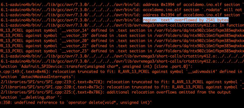
Overflow is bad news. That most likely meant that my ATTiny412 didn’t have enough flash memory to handle the libraries associated with the accelerometer. Sure enough, I reached out to Chris and asked him how large his compiled accelerometer code was. His script handled a bunch of stuff, not just the accelerometer, but it came out to 17kb. The 412 has 4kb.
Obviously a big lesson here is that its kind of stupid to make a breakout board with a 4kb microcontroller when larger options are available. If the whole point is to make a flexible unit for testing lots of components, the limited flash is really not that flexible. There are all sorts of inputs and outputs I’m not going to be able to plug in to my Reubino!
So I still hadn’t gotten an input working, and I was left with a few options. I could:
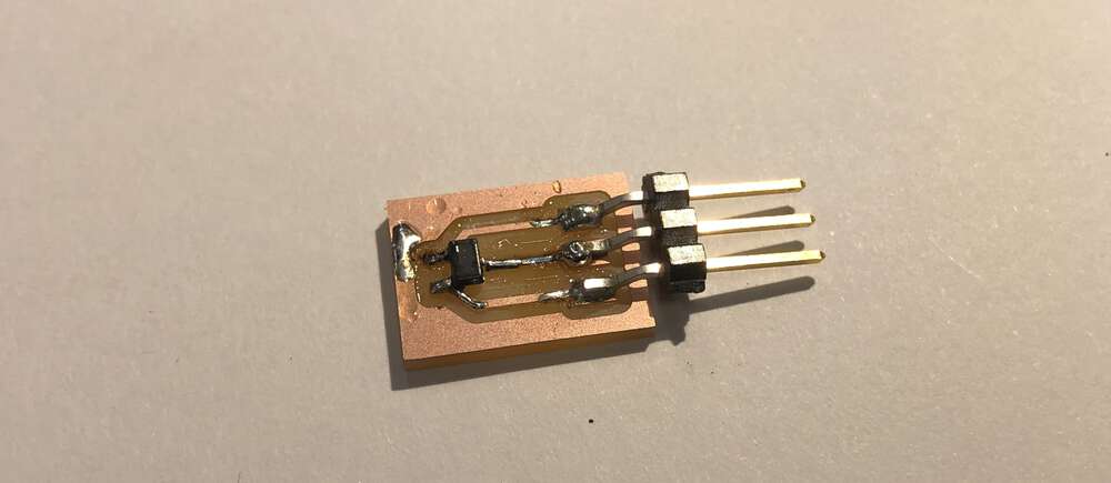
In the interests of stress and spiraling, I went with option three. And the modularity of my Reubino really shined. In about 45 minutes, I was able to design, mill, stuff and wire a super simple board that contained a Hall effect sensor (an A1324) and the three pins needed to run it. My favorite iron was in use and it had been a long day, so this is not my best solder job.
I plugged it in, pushed Neil’s hello world code, and fired up the serial terminal on my Mac. Where I saw … nothing. I thought my sensor wasn’t working. Disaster! But then I realized Neil’s code is using Serial.write() instead of Serial.print() so the data wasn’t going to the terminal.
void loop() {
   uint32_t result = 0;
   //
   // accumulate readings
   ///
   for (int count = 0; count < nsamples; ++count)
     result += analogRead(2);
   //
   // send framing
   //
   Serial.write(1);
   Serial.write(2);
   Serial.write(3);
   Serial.write(4);
   //
   // send reading
   //
   Serial.write(result & 255);
   Serial.write((result >> 8) & 255);
   Serial.write((result >> 16) & 255);
}
Just in the interests of testing, I switched all the values to Serial.print() instead, plus a print to confirm that serial was available. And sure enough, my serial terminal lit up with a bunch of garbage.
There are a couple potential causes here, but I think the main one is just weird formatting errors that happen when I play fast and loose with printing hex data to the terminal, including some integer values that might be overflowing. Wish I knew C++ better.
I was unable to get my Serial plotter working in the Arduino LED. I’d love to figure that out in the future, and generally get a better sense of where Serial.write() data ends up and how to use it. Instead I took the easy way out, and simply printed (instead of writing) the simplest of the values that Neil produced in his Hall effect hello world.
This worked fine. My serial terminal continuously printed some values, and those values did in fact seem related to the proximity of a magnet. Success!
Obviously a lot more to explore here. My final project isn’t heavy on output, so I’m hoping that by creating Reubino, I’ve frontloaded some work for the next two weeks. Which means that those assignments should go by faster and I’ll be able to return to some half-finished work: Casting a soft ball, getting an accelerometer working and reading serial data in a more useful way then just printing them to a terminal.
Wish me luck!
Files: Here are the traces and outlines for my Reubino exposed-pin board, ADXL343 accelerometer breakout, LED breakout, and Hall effect sensor breakout. I didn’t write a lot of original code this week, but here’s the final script I was running to get values from my Hall effect sensor.