Embedded Programming
This project gave me an especially difficult time. I have never worked with programming any electronics except for arduino before. I began working with my Atiny412 board from week 5, but struggled to make it work, and had trouble finding documentation on it. I found some helpful recources for the D11C (here and here).
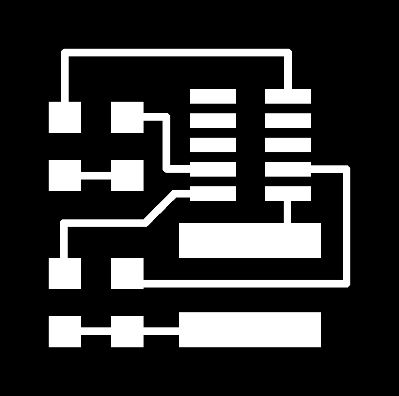
So I decided to use it instead. My programmer from week 3 has a D11C with a bootloader, so I used that and designed a secondary board to connect to it. The scondary board will have a button and an LED that will be operated by the D11C on the main board. With only a handful of components, I decided to make the board in Gimp. The blue LED has a 1k ohm resistor, and the switch has a 10k ohm pull-up and pull-down resistor. The boards will be connected by a 0.5mm pitch ribbon cable.
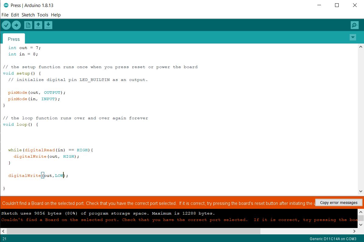
The board will operate by turning on the LED when the button is pressed. I wrote the code using the Arduino IDE. It uses a while loop to check if the button pin is HIGH, and if so, the LED pin is also set to HIGH. The LED pin is set to LOW outside the loop.
I first tested this code and circuit with an Arduino and breadboard. It worked as intented (after some minor tweaks), so I proceded to replacing the arduino with my programmer, and the breadboard with my secondary PCB.
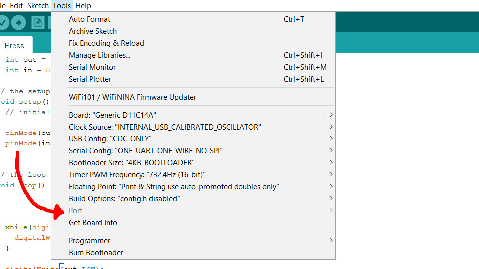
In the Arduino IDE, I installed the Fab SAM board definitions, and set my board to "Generic D11C14A". When I plug in my programmer, my computer makes the USB connecting sound (just as if I had plugged in a mouse or keyboard), but I am unable to choose a port for the board. The option (in the tools menu) is grayed out. After some troubleshooting, I moved on to the secondary PCB.
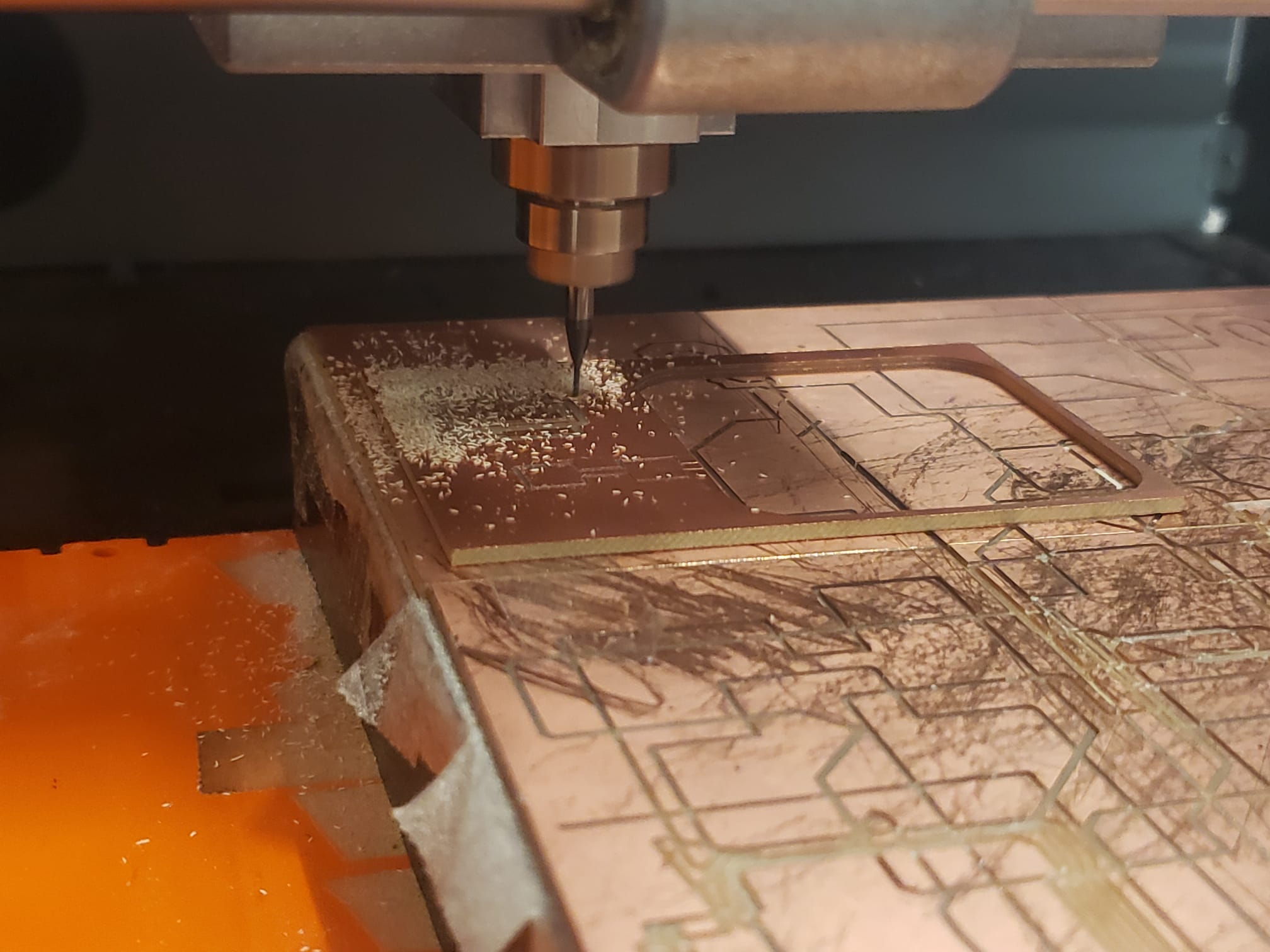
Below are the PNG files that I generated with GIMP to be cut on the Roland machine.

For the first cut, the DPI was incorrect, and the board started cutting too large. After I made the correct adjustment (from 300dpi to 993dpi), the milling when without any trouble. as shown below.
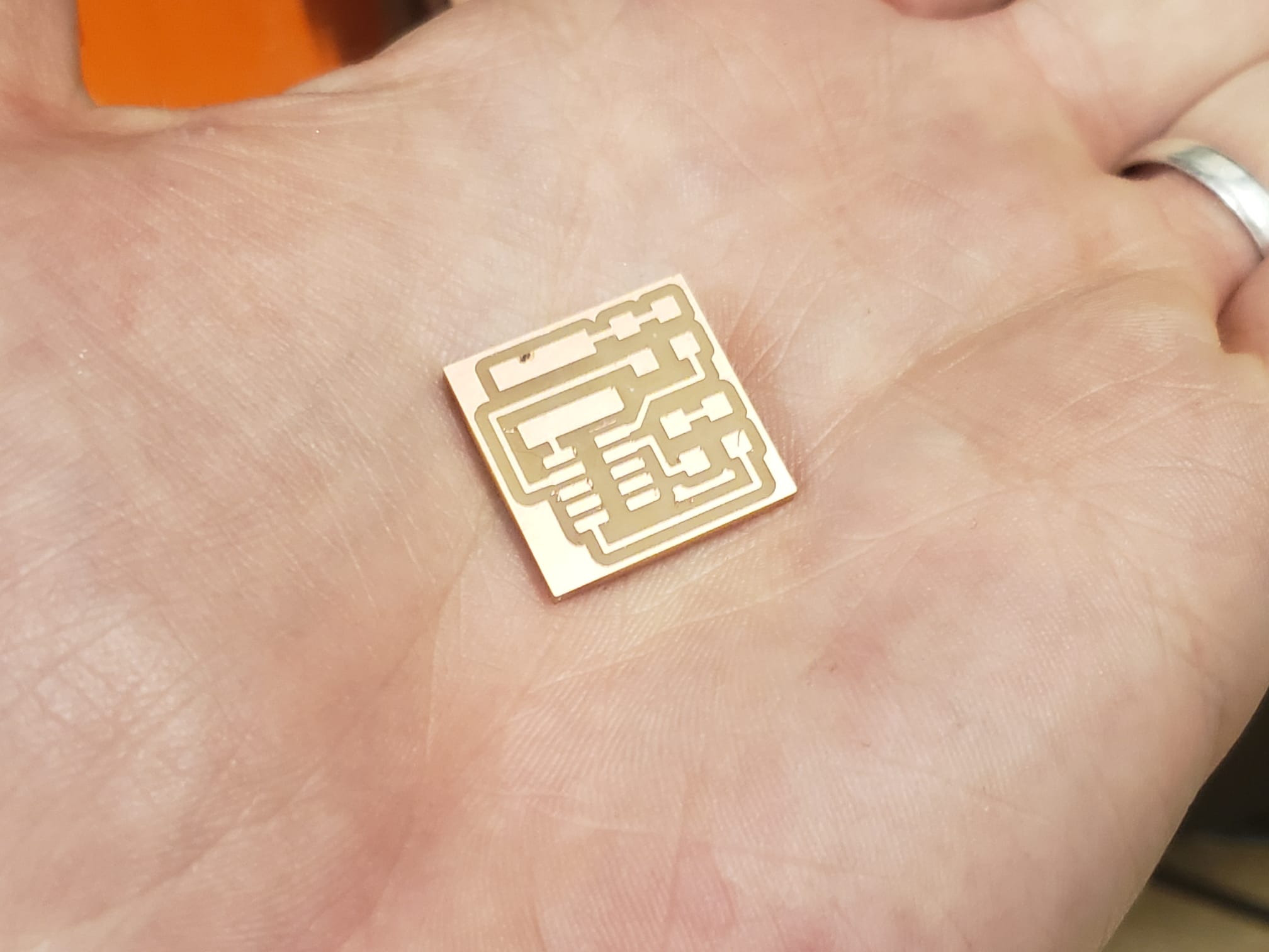
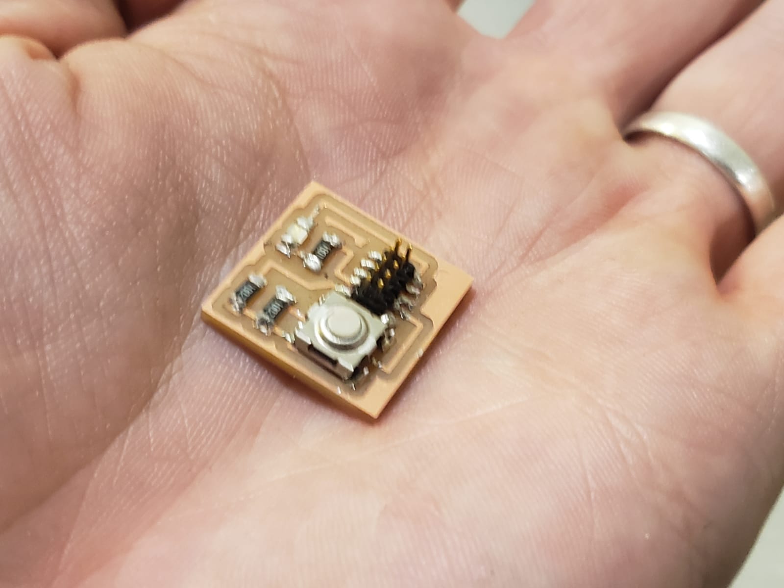
After cutting the board, I soldered all the components in place. The solder seemed to stick less to everything then usual, but there were good connections, to I moved on to testing.
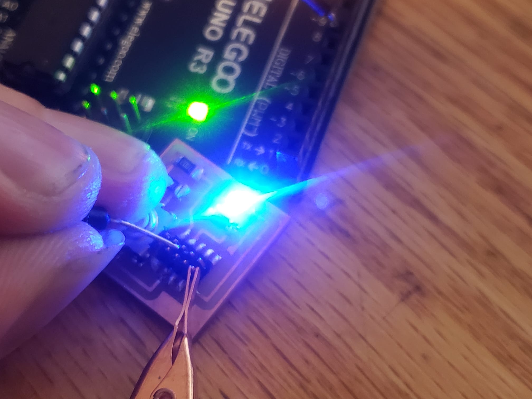
I connected it to my test arduino with my code, and the board worked as intented. The LED turned on when, and only when the button was pressed.
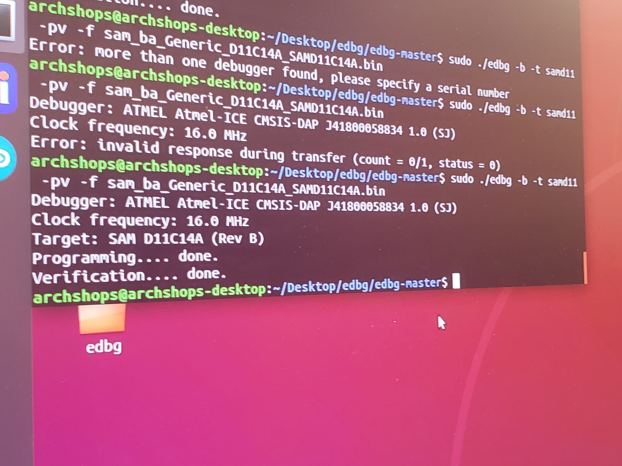
Then I turned my attention back to my programmer board. When the board is plugged into my computer usb slot, I can measure 5V on the power rail before the voltage regulator, and 4.3V after the regulator. I desoldered the voltage regulator and replaced it with a new one, and tested it. This time it measured a healthy 3.3V, but I still could not connect it to the port.
I had already uploaded the bootloader to my board, but I tried to upload it again just in case. It was successfully uploaded, but it made no difference when I tried to upload my arduino program.