For my board, I used an ATSAMD11C microcontroller. The data sheet explains what each of the pins means (as shown in the image below) and the specifications for the microcontroller. I needed to understand this processor in order to clearly understand how my board works.
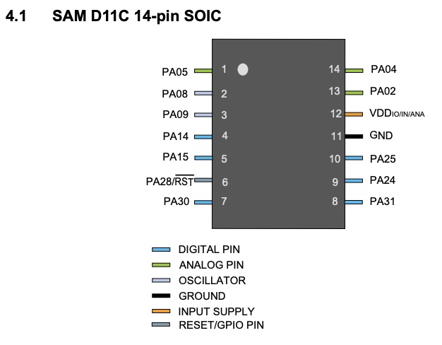 As you can see, there are several analog pins as well as several digital pins.
Analog Pin: Can take a range of values. This pin reads/writes voltage anywhere within a range from 0 to 5V. An analog pin can usually be used as a digital pin.
Digital Pin: Can only take one of two values (LOW or HIGH). Digital pins are mainly used as output pins. You can use them to check an on/off status of a switch (input) or you can use them to turn on/off devices (such as a buzzer, LED, LCD) using HIGH and LOW in the Arduino code, for example. Note that PWM (pulse width modulation) is a way to get analog results with digital means (using a square wave , for example blinking an LED at different frequencies that appears to the eye as different levels of light)
The D11C is part of the SAM D family of boards, Atmel brand. It does not need much power (low-power) and uses a 32-bit ARM processor. Higher bits means higher handling of data and higher ability of handling more RAM (memory).This version that I am using has 14 pins (10 of which can be used for input/output), including digital & analog pins. This microprocessor has 16KB flash and 4KB SRAM. Flash is a type of memory, which is cheaper and slower than RAM. SRAM is static RAM (as opposed to dynamic RAM, DRAM). This SAM D11C operates at a max frequency of 48MHz and reaches 2.46 Coremark/MHz. The frequency typically refers to the frequency of the main CPU clock / frequency at which the clock generator of a processor can generate pulses.
For programming my board, I wanted to be able to light up the LED with a certain amount of flickering when the button is pressed. Ultimately, I also wanted to use the extra pins to be able to drive a motor (which may be useful for my final project) as well as attach a speaker which would be able to output a music file or set of different music files (which may play upon pressing the button too). Lastly, I want to attach a buzzer (optional, for an alarm) and perhaps an RTC (real-time clock) attachment to be able to set timers.
Although I used Arduino programming one time before, I was still extremely behind on Week 5, when I was supposed to mill and prepare my board for Arduino programming. Routing and exporting my PNG files to use in the mods system for the Roland mill was quite difficult, since I kept trying over and over and facing many roadblocks with exporting the PNG's that would mill the board properly. So for this week I decided to start with something simpler with regards to programming, in order for me to have enough time to actually get the board milled and set up!
You have either AVR or ARM, and UPDI or SWG.
We need to write C programs for the processers used in this class. We'll be given an example program and then modify that program.
For this class, I will use the IDE (Arduino IDE) interface for my programming. We'll install the IDE and then install the cores which pull in a toolchain and talk to the programmer to load your program.
First, I need to load the bootloader (edbg) > JTAG > D11C > usb > bootloader (to change the program)
NOTE: need to solder button on right (parallel lines then get connected when button is pressed)
Extra credit: other programming languages (python??) & development environments - WHAT IS A DEVELOPMENT ENVIRONMENT??
1) Arduino > Tools > Programmer > Atmel SAM0ICE
fab.cba.mit.edu/classes/863.21/Architecture/people/LauraMaria/index.html
How to use bootloader & what is a bootloader:
http://mtm.cba.mit.edu/2021/2021-10_microcontroller-primer/
https://mtm.cba.mit.edu/2021/2021-10_microcontroller-primer/fab-arduino/
Follow these instructions for installing the bootloader onto your PCB board (for mac, using edbg):
https://mtm.cba.mit.edu/2021/2021-10_microcontroller-primer/edbg/
1. Click on the link for "edbg mac build 2021-09-16" on the site above, to download
2. Double click on the download file, click "open" to the popup or just leave the popup, and go to your Mac security settings and make sure to allow the file to be downloaded/opened. Settings > Security & Privacy > General > Allow Apps Downloaded From... edbg
3. Go here https://github.com/ataradov/edbg and download the code (Code > Zip file > open zip file )
4. Install homebrew for mac if you don't already have it: https://brew.sh
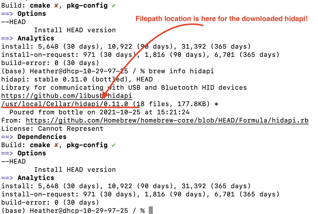
5. Type the following into the Terminal: brew install hidapi
6. Try typing in LIBS += /usr/local/lib/libhidapi.a CFLAGS += -I/usr/local/include/hidapi into the terminal. It might not work; don't worry.
7. Type brew info hidapi into the Terminal. A bunch of code/text will appear in the terminal; in there somewhere is hidden the location / file path of the hidapi that you have installed. For me, it was in /usr/locatl/Cellular/hidapi filepath location! You can find this by typing in cd ../ into the terminal several times and then ls in the terminal until you see usr show up in the list of folders / in the current folder directory when typing in ls.
8. Next, type in the following into the terminal, first line and then press enter, and then second line and then press enter.
LIBS += /usr/local/lib/libhidapi.a
CFLAGS += -I/usr/local/include/hidapi
***I GOT STUCK AT THIS STEP!!!!*** I went to office hours but there were some issues with Mac, and the TA wasn't sure how to get me through the step I was stuck on.
The TA verified that edbg was installed on one of the computers in the archshop already. So, we decided to go with that instead.
What is a bootloader ?
The arduino bootloader allows arduino the IDE and compiler to load programs onto the PCB board. The bootloader needs to be programmedontothe PCB board in order for this to be possible.
For the ATSAMD11 and ATSAMD21 series microcontrollers, this means finding one of the cmsis-dap tools and using edbg, pyOCD or openOCD in order to load the bootloader binary on the board. That binary is specific to whichever microcontroller you’re using. In my case, I used a SAM D11C and edbg.
Once the bootloader has been loaded (via the SWD pins), we can plug the PCB board in via USB to the computer program and communicate with it (e.g. use Arduino IDE programming to control buttons, LEDs, and other devices).
Here are the steps the TA took to help me get the bootloader onto my PCB board:
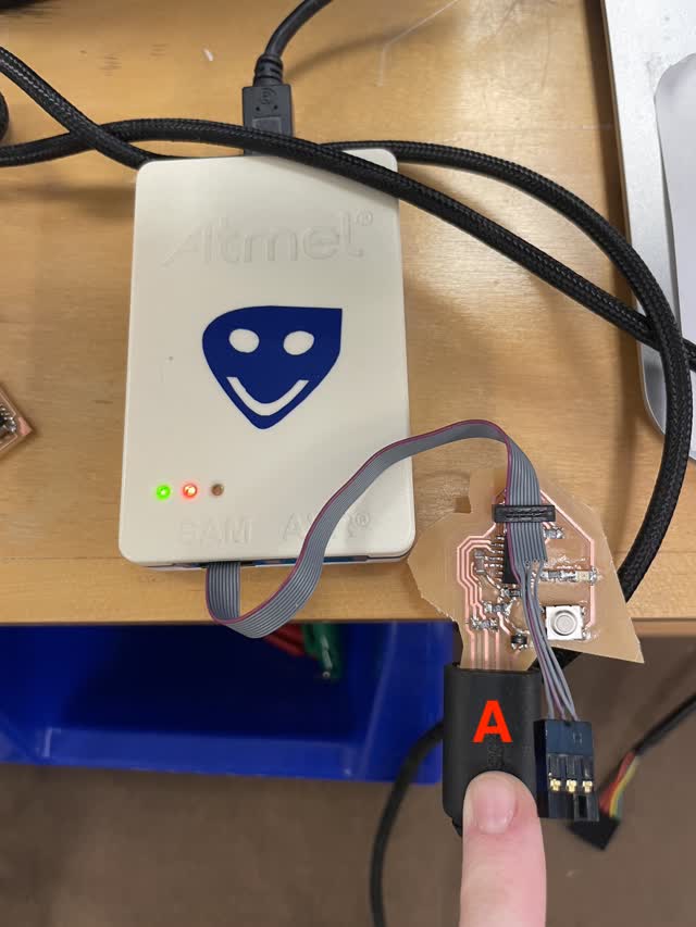
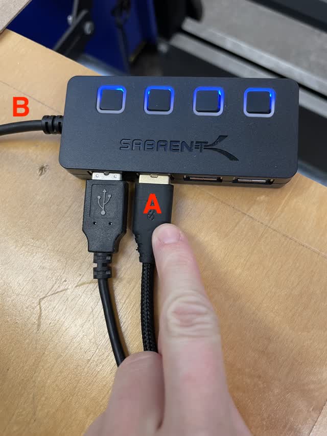
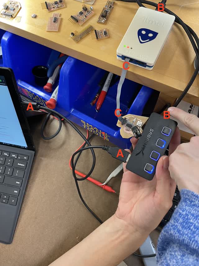
1. Connect everything per the photos below (connect A to A, and B to B, etc.)


2. Navigate to ~Downloads/edbg within the archshop computer near the solder stations, using the cd, ls, and cd ../ commands in the Terminal command line on the computer
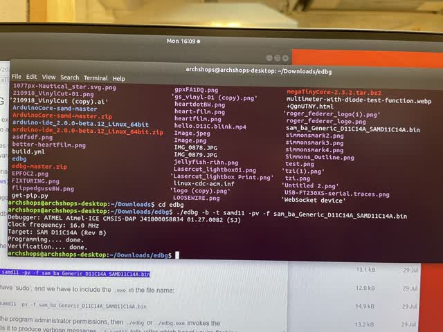
3. Type into terminal ./edbg -b -t samd11 -pv -f sam_ba_Generic_D11C14A_SAMD11C14A.bin (SHIFT INSERT to paste it)
This page has useful info on this: https://mtm.cba.mit.edu/2021/2021-10_microcontroller-primer/edbg/ (you can use the code and leave out the sudo)
Yay! All done now - the bootloading is complete!
Note that the next step, Step 3 on the website which is the Arduino setup, is not working for Mac right now. The TA's are working on fixing it and hopefully it will be working by tomorrow.
With TA Laura:
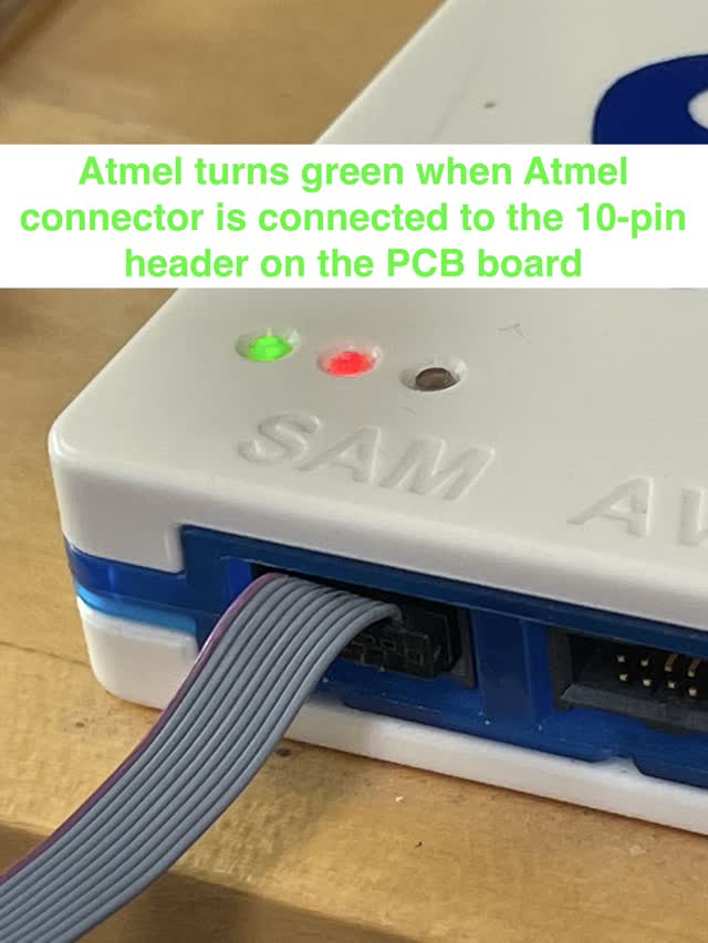
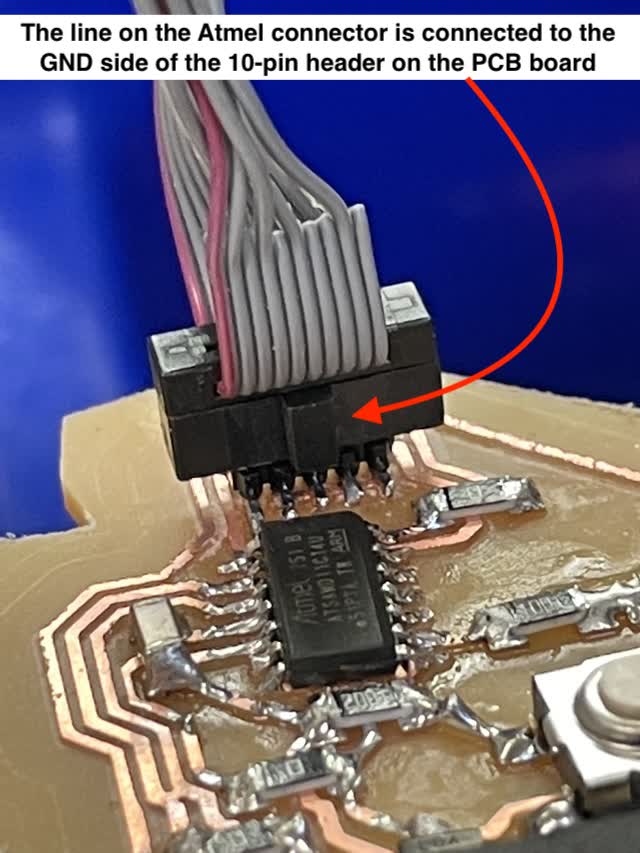
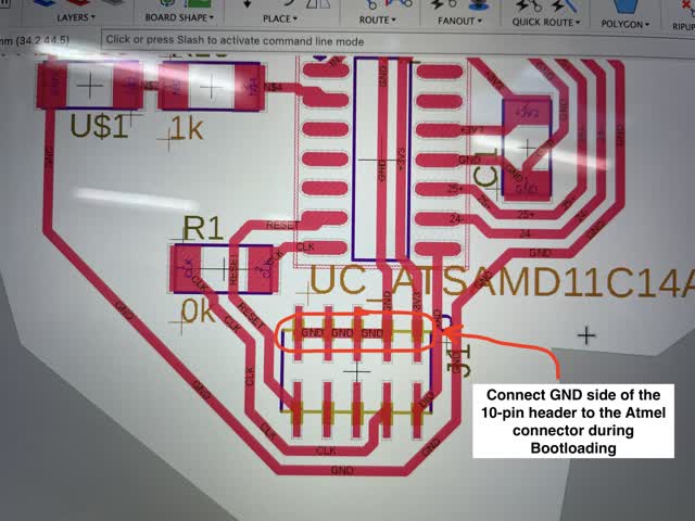
When connecting your board to the Atmel for bootloading, GND along the 10pin connector should be lined up with the line on the little connector thing on the Atmel. And the Atmel should be lit up green.
Atmel is connected to computer, and to the board, board is connected to the USB for power, and USB is connected to my laptop for power. See below for the connections (A connected to A, B connected to B, C connected to C):
The code should say Programming... done, and Verification... done. (As shown below)
Open Arduino.
Tools > Board> Mattairtech Generic D11C14A (Follow quentin's tutorial to add that library for it in Arduino)
Use PA08 for the LED pin specified. (pin 8)
Noticed that I had two traces connected - Used exacto knife to carve that part out and multimeter with the TA to check that those traces were no longer connected. I checked by plugging my board into USB power and using the black and red multimeter leads to check between each 3.3V and GND connection that the multimeter would read 3.3V when on the V (voltage) setting of the multimeter dial.
So everything seemed fine...
We went onto Arduino and tried to see if Arduino would recognize the board, and it would not! Even though the bootloader was properly loaded!!
So I went to office hours yet again. This time, with Anthony Pennes at the EDS / EECS shop.
He checked with the multimeter as well, and everything seemed fine. He also mentioned that the cardboard piece that I put on the back of the USB connection part could be causing issues. However, after we finally put the board in & out again many times, he finally mentioned that it could just be a soldered connection that is loose. Anthony suggested that I re-heat all of the solder joints again just to ensure all of them are properly soldered well together.
Yay! I was able to get the LED to light up!
Next, I added a library to allow Arduino IDE to program the D11C microcontroller on my board.
https://mtm.cba.mit.edu/ (Practical Microcontroller Primer > Fab Arduino SAM guide > Part 3 (Arduino Setup)
The instructions to setup the Libraries in Arduino IDE for SAM D11C are as follows:
These boards aren’t supported by arduino out of the box. In order to make that happen, we need to open up arduino and do:
Then I went to Arduino and:
Tools > Board > Fab SAM Core for Arduino > Generic D11C14A

Tools > Port > usbmodem14101 (note: this won't show up if your soldering isn't done right; check with a multimeter and re-heat your solder joints if you're having troubles; plug the USB of the PCB board into your computer for power, then connect the leads of the multimeter one lead to GND and the other lead to either 3.3V or 5V along all traces of the board at different locations to check that everything is soldered properly, with the multimeter on the Voltage (V) setting)

And then I loaded the Button example sketch in Arduino (File > Examples > Digital > Button)
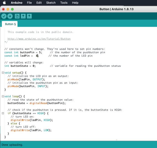
Note that I changed the pin numbers for the button and the LED to the pin numbers on the SAMD11C microcontroller on my board. I had connected the button to PA05, and the LED to PA08 (shown in the schematic/labeling at the very beginning of this page and on the data sheet for the microcontroller).
So then I changed the code in the beginning to: buttonPin = 5, and ledPin = 8, note that you should leave out the "PA0" part.
YAYYYY!!! It WORKS!!!
The group assignment is to compare the performance & development workflows for other architectures. For this, I teamed up with Raghav and Emily for the group project. *test response times / difference btwn chips & why to use one vs the other*
First of all, here are a couple types of architecture:
See here for some more details about these types of architecture, or view this URL:
https://vivadifferences.com/5-major-difference-between-von-neumann-and-harvard-architecture/
Here are some different families of microcontrollers:
ARM and AVR are 2 different families of microcontrollers. ARM micro-controller and AVR micro-controller differ from each other in terms of different architecture and different sets of instruction, speed, cast, Memory, Power Consumption, Bus Width etc.
Harvard Architecture is used for Atmel AVR (for example, Attiny) and most ARM processors (for example, D11C and similar microprocessors) are also made with Harvard architecture. To understand the difference between AVR and ARM, you can go to the link below. AVR microcontrollers are made by Atmel is made by Apple, Samsung, Nvidia, etc. AVR is the most popular microcontroller and is very cheap and used for robotic applications, while ARM microcontrollers are the most popular for embedded systems because they have a lot of features.
https://www.geeksforgeeks.org/difference-between-avr-and-arm/
For the group project this week, Emily found a really good site that a TA made for past year.
TA Quentin Bolsee has done a great job explaining the group project that we need to complete this week, so we decided to reference his work. We only had one board working - a D11C - so although we intended to compare the Attiny to the D11C ourselves with regards to the time it takes to echo, we ended up only being able to use the D11C and to discuss with each other the way the different boards are programmed and connected in order to allow the boards to be programmed with Arduino IDE. Below are the links to the websites that TA Quentin made:
fabacademy.org/2020/labs/ulb/assignments/week09/
fabacademy.org/2020/labs/ulb/students/quentin-bolsee/assignments/week09/
Here is a table comparing several numerical values, gathered from https://www.microchip.com and https://www.espressif.com/ :
The above gives you some idea of the differences in performance of the different microprocessors that can be used for PCB boards.
Here are some of the differences between setting up the boards:
To program Attiny, you need programmer & intermediate board (that's how it's loaded), whereas D11C can be programmed directly because it speaks serial. Raghav was particularly knowledgeable about this, and we also found a site that TA Laura made this year explaining how to connect and set up the boards. The connectors for setting up the Attiny are shown below.

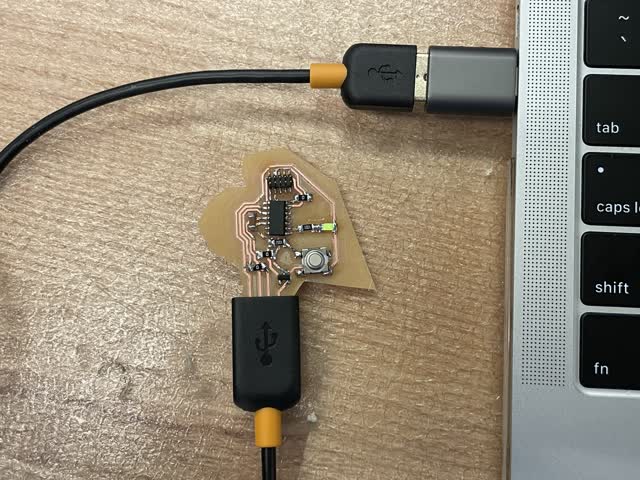
For the D11C, you do not need as many connector boards. All you need to set it up is the PCB board itself, the USB connector, and the Atmel for bootloading, as I had described above on this page.
Here are some other notes from this week:
Types of memory:
Arduino(s) are families of boards, a toolchain to load a program, a set of libraries, an IDE for development, a set of bootloaders, and a geometry for expansion. We are making our own Arduino boards in this class. Thus, we will be installing the Arduino environment (GCC toolchain for the processors).
Here are some notes on what I learned this week:
For more advanced applications:
Useful website from other students who took (or are taking) the class:
created with
Website Builder Software .