decided to try eagle / fusion.
the ATSAMD21E seemed? the closest to regular arduino.
use jake's eagle tutorial.
... got stuck on figuring out a routing strategy..
have i bit off more than i can chew for my first board?
start with a one-sided board!
which chipset?
ATTINY = AVR
ATSAMD or SAM = ARM
design considerations
at the end of the day, maybe i want to make a motor controller..
demircas advice: try designing one of neil's boards in eagle, and adding the led and button.
stick to the ATSAMD21E since my D11C worked. Should have an easier time communicating to each other once networked. Also, the example ATTINY boards (communicate in serial?) use the depreciated FTDI (6pin) connectors.
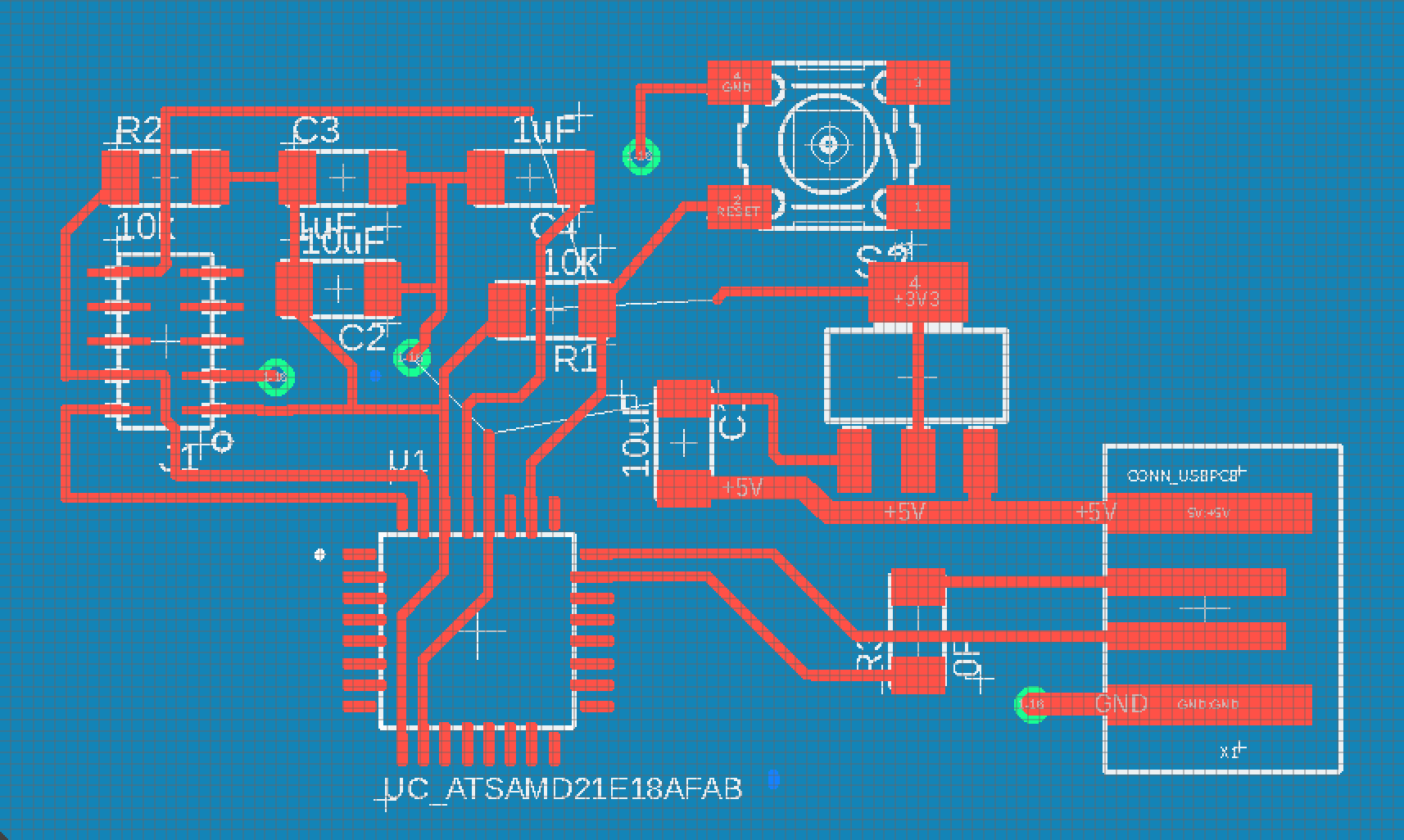
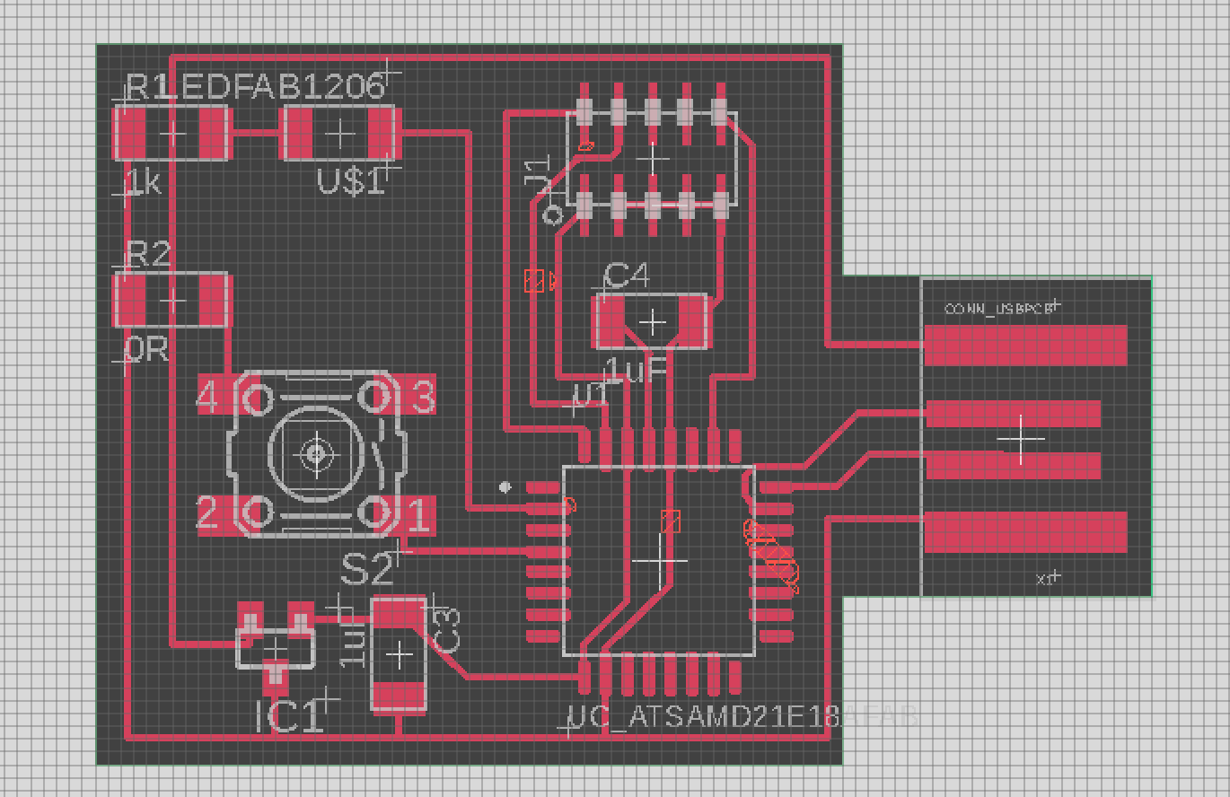
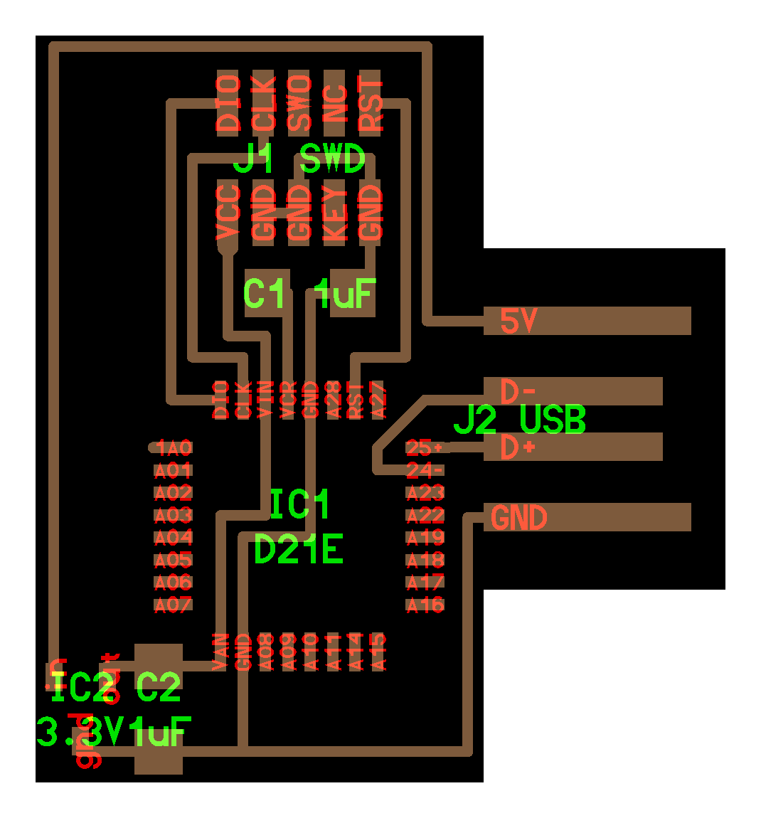
neil's echo ATSAMD21E board and components.
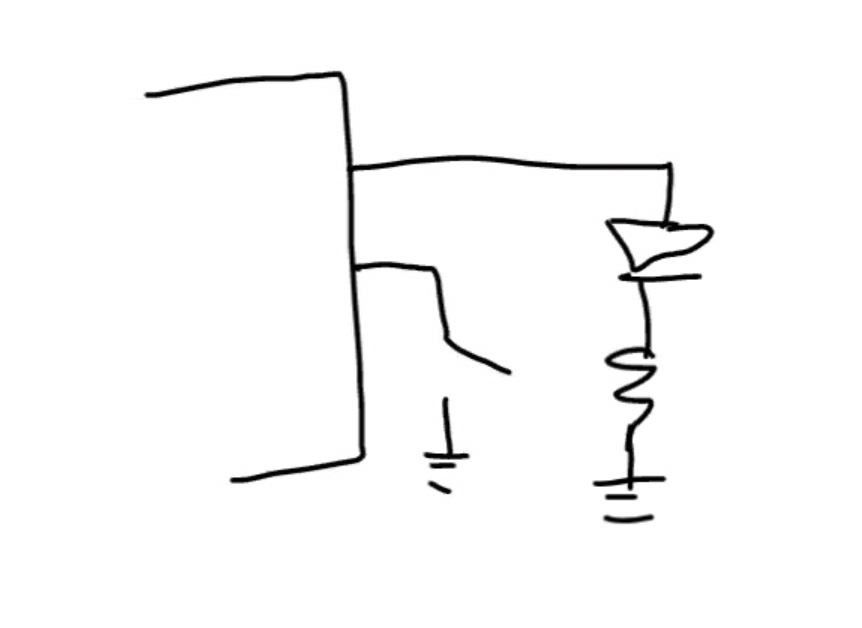
neil's add led and button drawing
eagle view
"display all"
key commands:
• net
• name
• add
• route
• rip up
keep track of units of endmills in mm.
what are good trace widths?
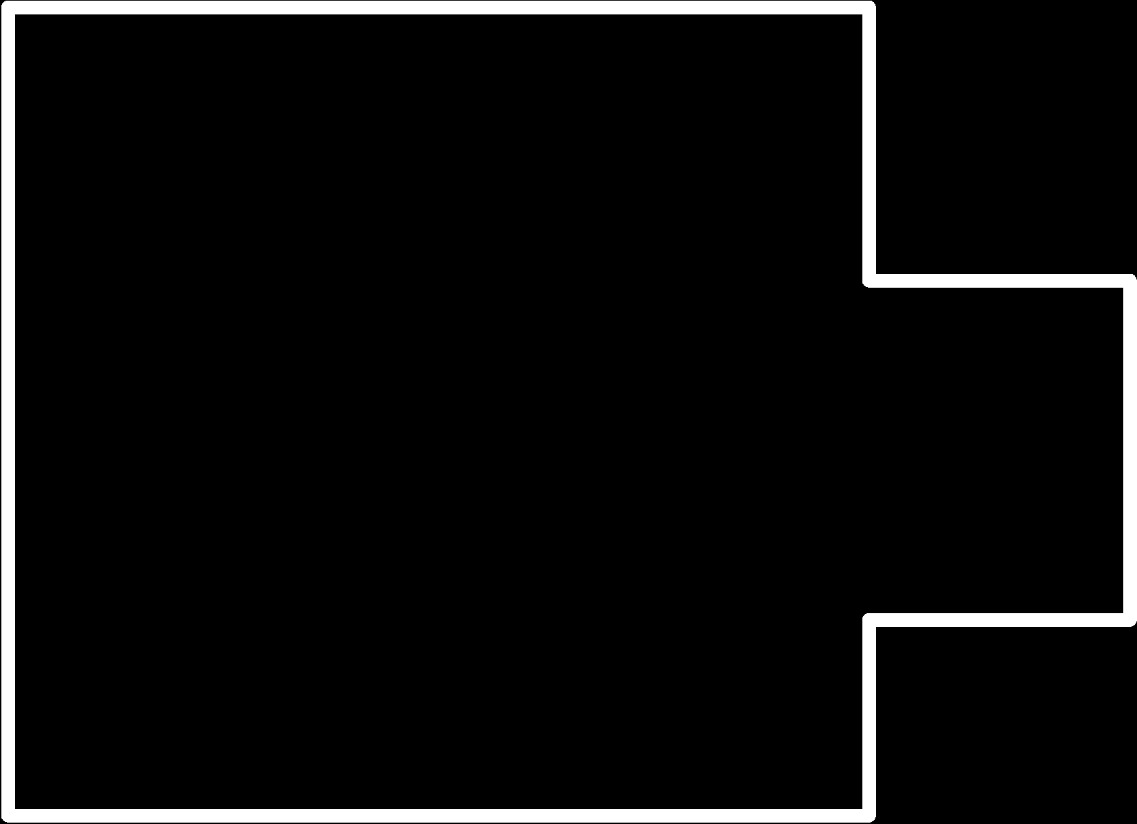
struggled exporting the outline with "line". remember to be generous with room around components for the DRC (design rules), the scale is deceiving, these things are tiny. bump linewidth up (not zero, thx kevin).
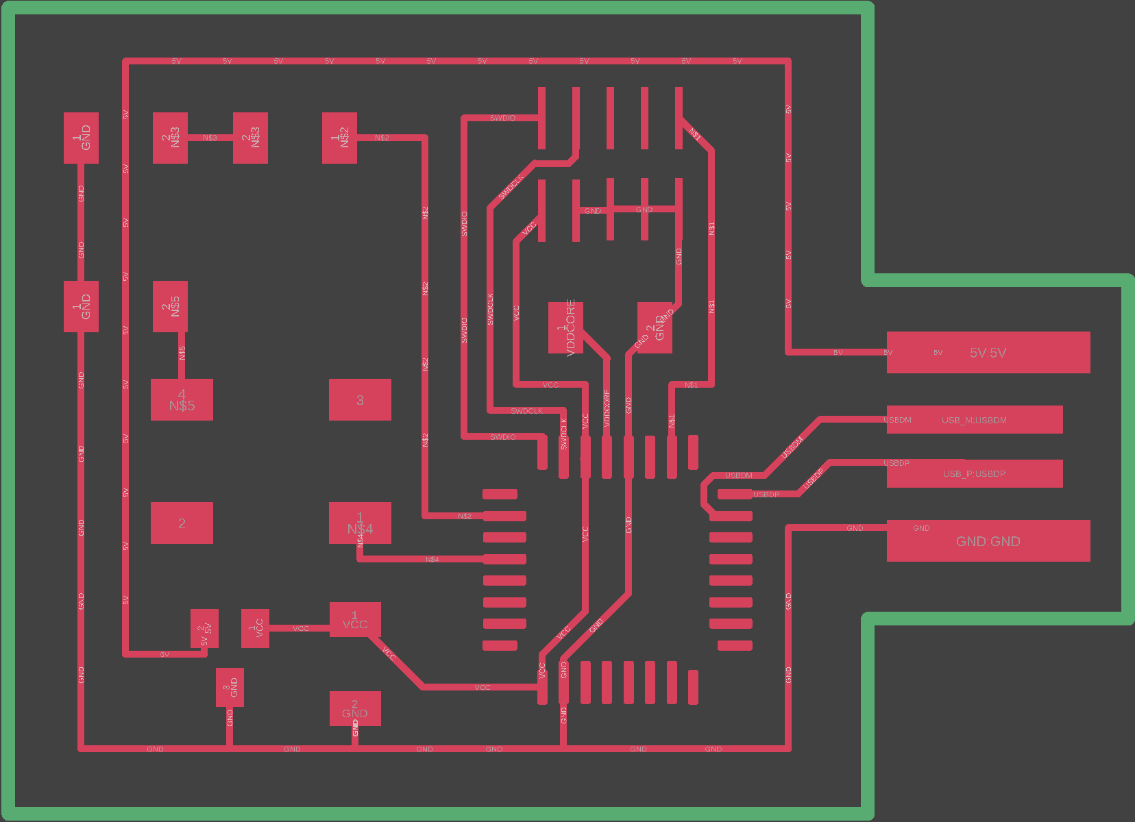
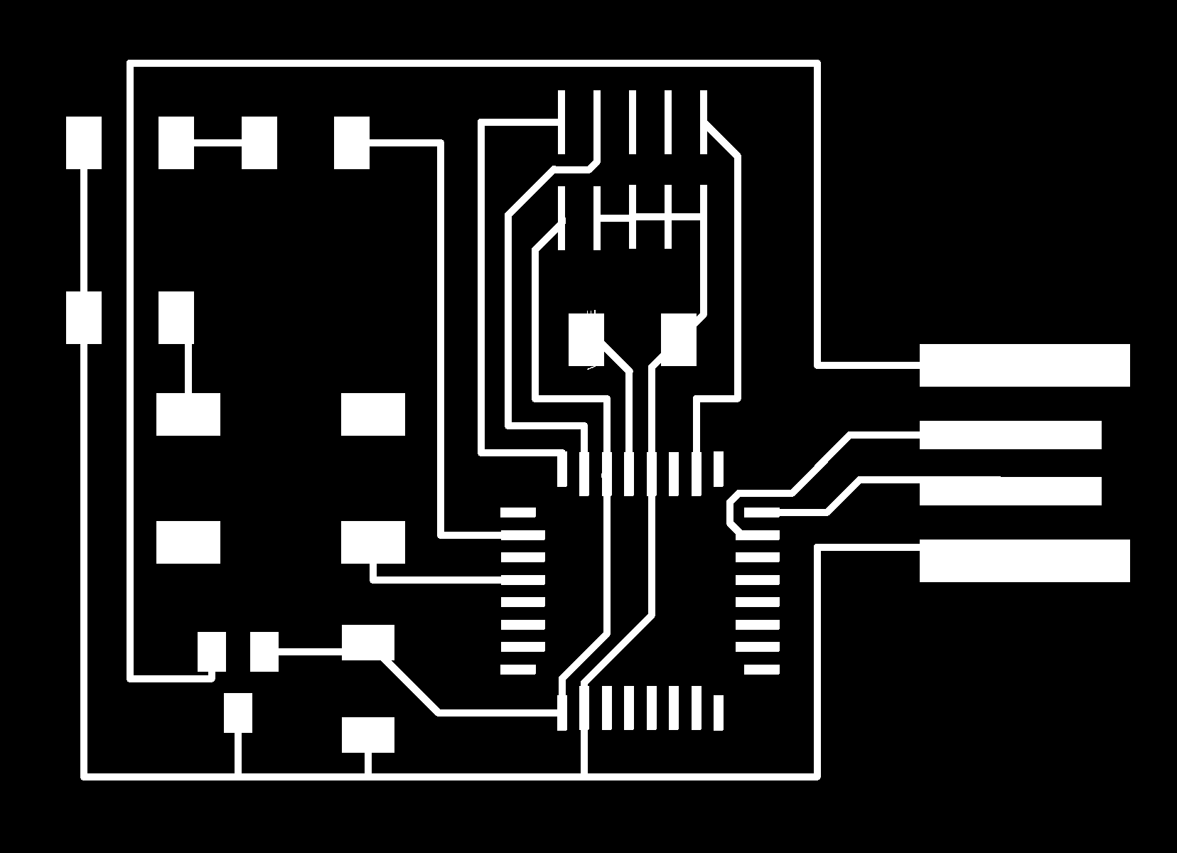
export board to png
at archshops: open up terminal, and a browser window to mods. import the traces png.
refer to archshops modela tutorial
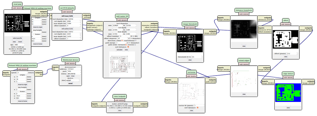
using mods to convert .png to toolpaths
workholding: i used the roland modela srm-20 to cut the pcb. check the size of the board after importing the .png to mods. find a pcb blank that fits the board design. use double-sided tape to hold down the pcb flat onto the spoilboard.
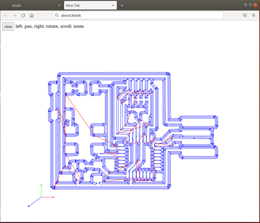
trace toolpaths from mods
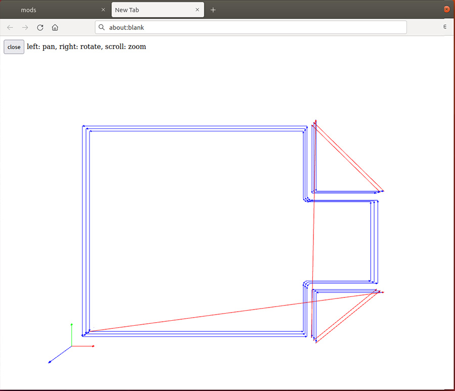
outline thru-cut toolpaths from mods
• adjust offset (0-4) to clear between traces.
• 1/32" sq endmill for outline.
use standard depths in mods.
toolpath window opens when you hit "calculate"
jogging the spindle through mods is a little cumbersome.
once you get close to XY zero, go to Z= 2mm
you have to zero the z-height by loosening the endmill in the collet, and letting it touch the surface of the pcb
you can only jog when the srm-20 door is closed.
opening and closing the door sometimes gives an error in terminal.
reset the blinking green light on top of the modela,
and try zeroing again.
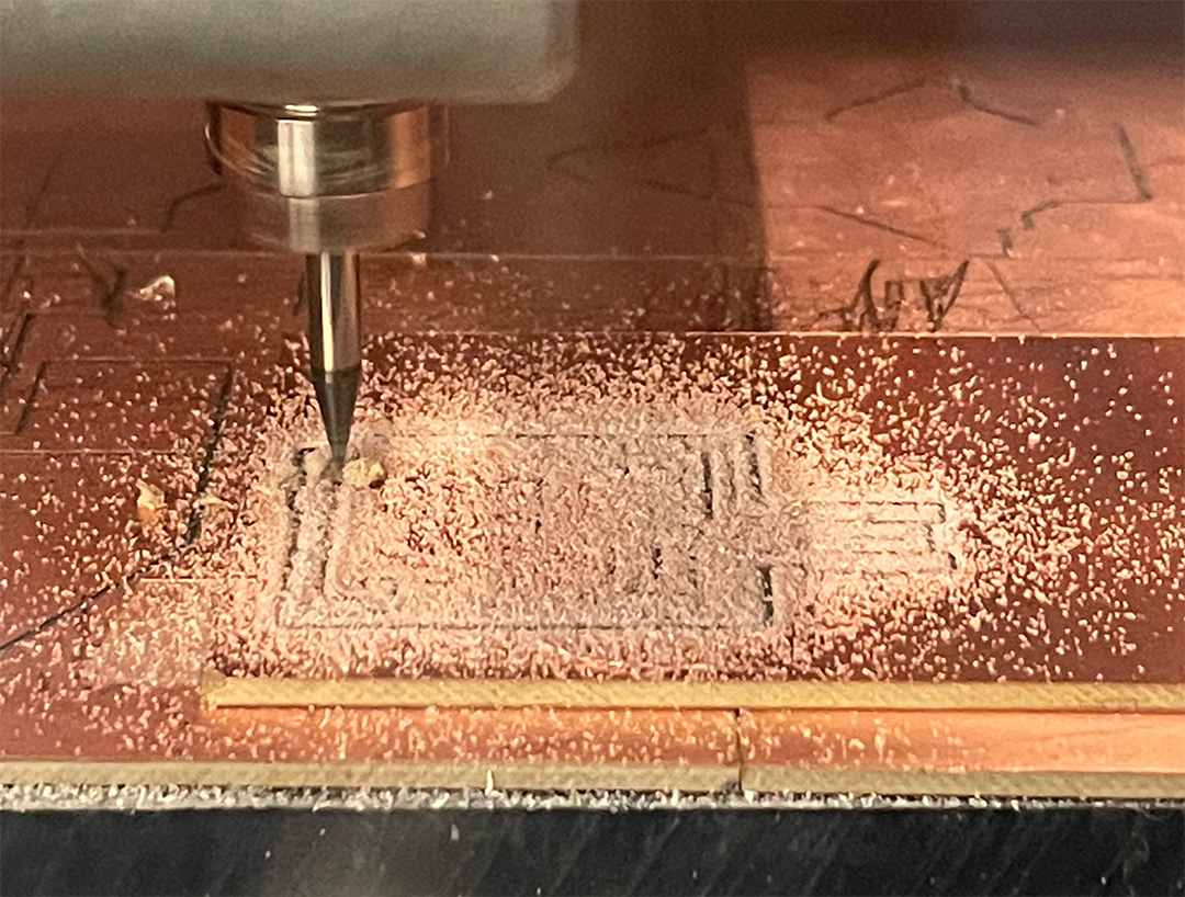
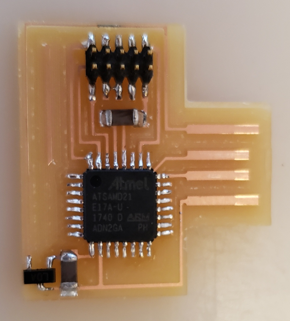
mill baby mill
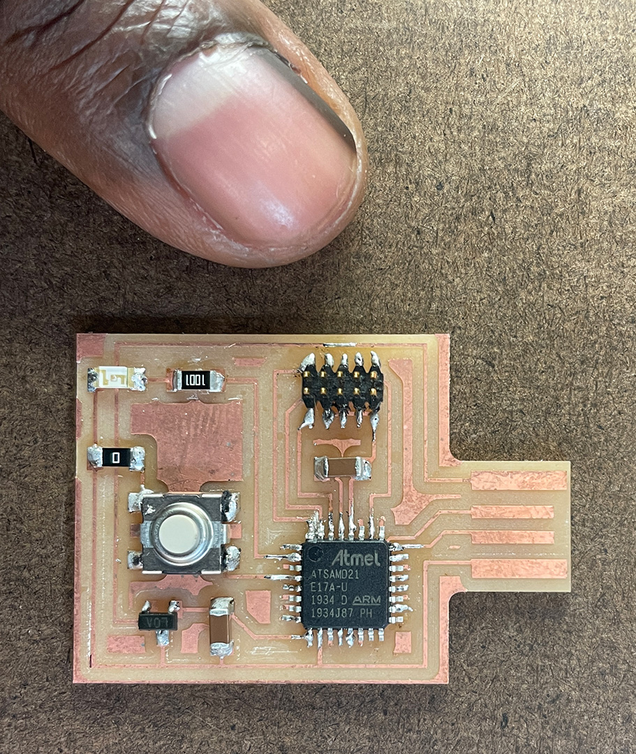
its tiny
next time, bump trace widths up. i needed an exacto knife to do surgery between two pins.
how to figure out polarity of the 1206 LED?
i looked at neil's D11C blinky board
apparently the resistor and LED arrangement doesn't matter.