TL;DR
thnks to Quentin for all the support.
struggled using ebdg with windows and mac, but had success with linux.
i have a Mac M1, so i wanted to be able to bootload with that.
refered to MTM EDBG Mac M1 primer.
success bootloading with openocd on Mac M1
EDBG to SAMD21
EDBG on Windows:
I was unable to boot from a windows machine in archshops, using Atmel ICE.
when trying to run ./edbg.exe, this was the error:
"exec format error"
(was it even a windows machine? maybe i needed to include “sudo”).
EDBG on Linux (success)
I was able to boot from a Linux machine in CBA lab.
(…on my second try)
flip the connector orientation.
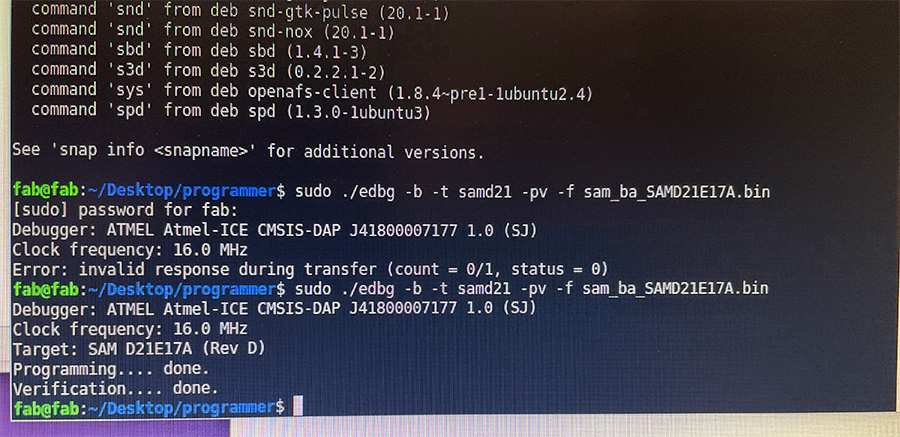
successful bootload on Linux > EDBG > SAMD21
refer to EDBG Mac
instructions:
• turned on rosetta on terminal
• brew install edbg
• brew install hidapi
this is where the issue is (please ask Quentin for details)
edbg struggles to find the hidapi.h header file in the Makefile
Reina states a work around here.
Quentin tried to explicitly include the hidapi.h header file
we needed to install pkg-config, this helped
but still no boot
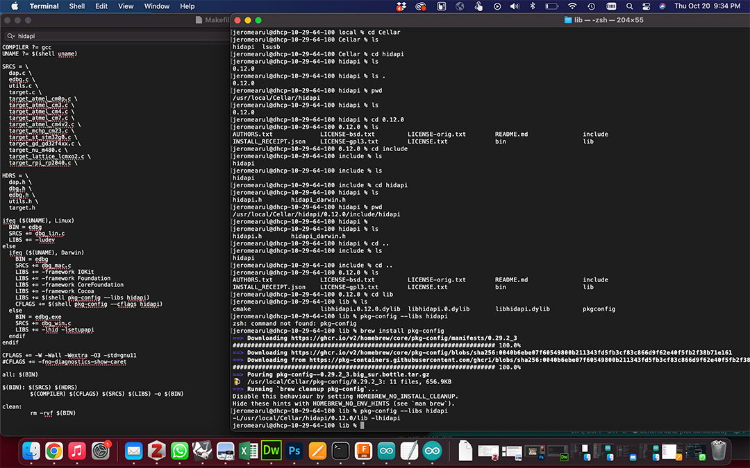
explicit call hidapi.h
brew install pkg-config
OpenOCD on MAC M1 (success)
refer to openOCD primer
openOCD was the solution we decided to implement.
• brew install openocd
include openOCD config file in the same folder as binary.
(quentin used his own source).
success!
BONUS!
because openocd was installed, the Burn Bootloader in Arduino IDE finally worked!
this will be my go to
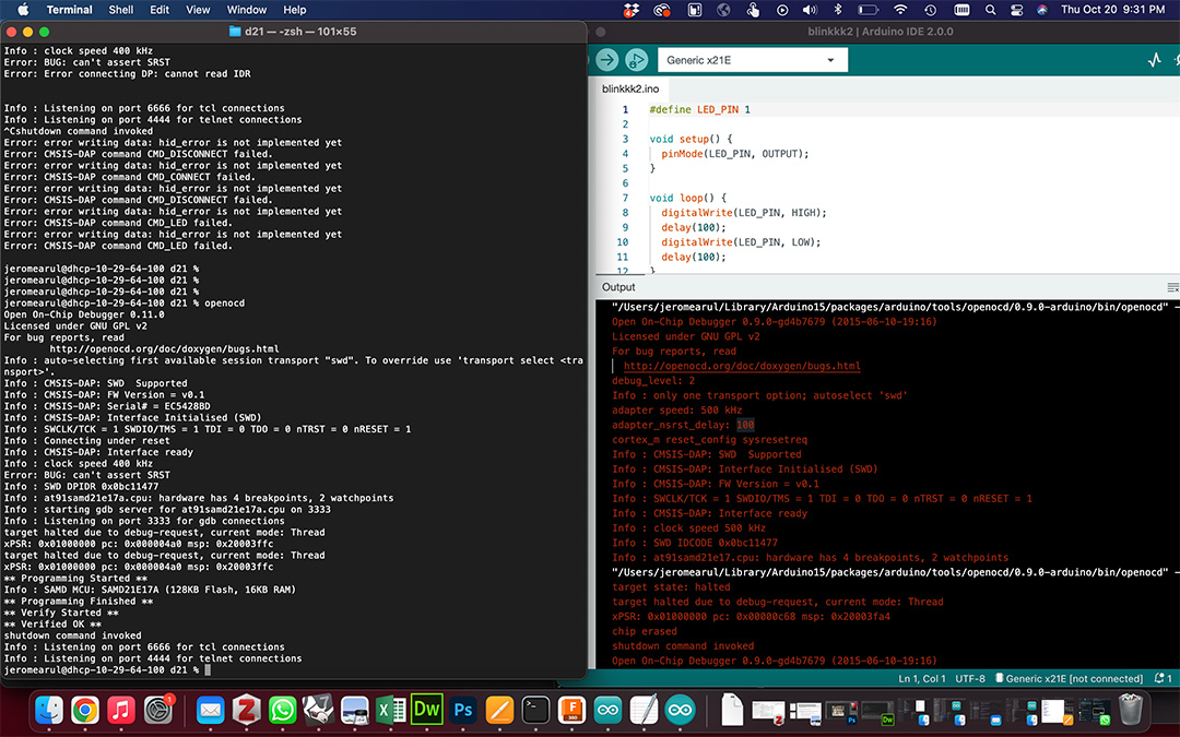
openocd boot and arduino "burn bootloader"
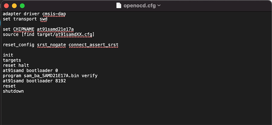
quentin's openocd config file
openOCD resource 1
openOCD resource 2
hardware debugging
Anthony made a funny face when he looked at my board.
Quentin confirmed that I had a lot of cold joints.
Next time, use flux.
refer to mtm microcontroller primer.
hardware results from trying to bootload:
• the 10-pin connector (Cortex Debug Connector for JTAG) was probably loose. flux > resolder.
• we cut the VCC line to the JTAG header (the programmer and target board both had 3.3V regulators, which would interfere? with each other. 3.3V regulator got hot.)
• my LED was backward… (point green edge to gnd) that’s why blinky didn’t work.
• my sketch pinout was wrong: its not Pin 2 and 4. it’s Pin PA01 and PA03 on samd21 schematic.
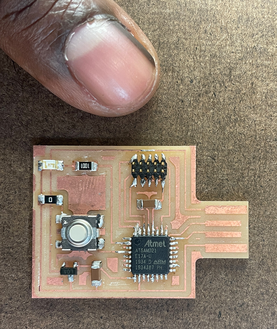
• so the samd21 chip itself was soldered “fine”.
• i was able to bootload the board (linux + ebdg, and mac m1 + openocd)
• compile and upload a sketch through Arduino IDE.
• and some of the circuit was somewhat successful.
still gotta resolder with flux.
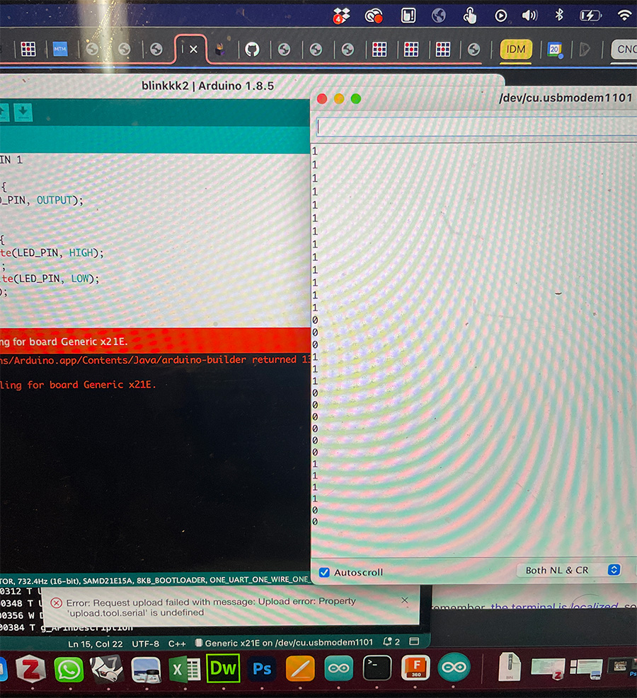
button press > serial print = 0
resoldered the LED, and it works!
other SAMD21 resources:
• Quentin’s repository of ARM / SAM / arduino core binaries
• Quentin's SAMD21 devkit
• a good fab academy project