Electronics Production
Overview
Workload: ● ● ● ○ ○
Previous Knowledge: ○ ○ ○ ○ ○
Current Knowledge: ● ● ● ● ○
Concepts
PCB Fabrication, Milling, Soldering
Software
Mods
Assignments
1. Characterize the design rules for your in-house PCB production process
2. Make an in-circuit programmer that includes a microcontroller
• Mill and stuff the board
• Test it to verify that it works
Extra-Credit: Send a PCB out to a board house
Documentation
Regarding workload, this was a less demanding week. Although the concepts were completely new, I could better focus on only one task - making the PCB - instead of balancing multiple tasks required last week - Git, web development, vinyl cutter and laser cutter.
I feel that I learned a lot about electronics over the past week, but still feel that my knowledge is very limited and will have to work a lot to design and programme my own circuit board - I look forward to doing that over the next month!
Theory
Printed Circuit Board: A printed circuit board is a medium used in electrical and electronic engineering] to connect [electronic components to one another in a controlled manner. It allows each of the components to communicate with the system of a chip through wires in a very precise organization.
It can have multiple layers and necessarily has at least two elements:
• Conductive Layer: made by copper traces that conducts energy
• Insulator: made with non-conductive material
PCBs are made up of a variety of different electrical components, each vital to the functionality of the device to which it will belong:
• Microcontroller (MCU): can be seen as a small computer, and this is because of the essential components inside it; the Central Processing Unit (CPU), the Random-Access Memory (RAM), the Flash Memory, the Serial Bus Interface, the Input/Output Ports (I/O Ports), and in many cases, the Electrical Erasable Programmable Read-Only Memory (EEPROM)
• Resistors: one of the most crucial and common components in a PCB. They transmit an electric current in order to produce a voltage and dissipate electric power as heat
• Connector: used for connecting conductors to printed circuit boards for the easy and safe transmission of signals, data, and power
• Transistors: amplifier used to switch or control the electronic signals in a board
• Capacitors: hold electrical charge within the board and release it whenever more power is needed elsewhere in the circuit
• Voltage Regulator: component of the power supply unit that ensures a steady constant voltage supply through all operational conditions
Practice
In order to make our PCB with a micro-controller, we must:
Design the board (not in this case) > Cut the board > Select components > Solder components on the board > Program the board
1. Cutting the Board
Tutorial: Arch Shop Tutorial - Modela PCBS
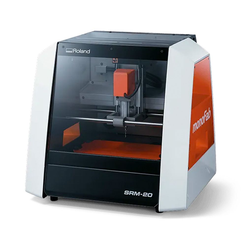
Equipment: Desktop Mill - Roland monoFab SRM-20
1.a. I took a PCB board blank and attached it to a flat and clean part of the cutting bed with double sided tape.
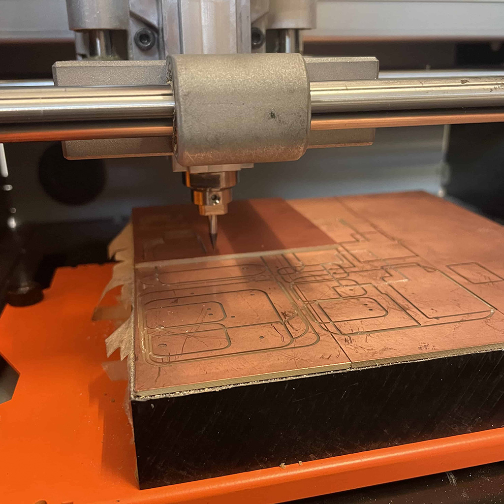
1.b. The first part to be done is etching to create the interior copper traces. For doing that, I took a 1/64 endmill and installed it on the machine.
*The endmill is extremely thin and fragile, so it is essential to be careful when handling it.
1.c. I accessed Mods on the computer and started moving the origin in order to position the endmill in a point that optimizes the production, trying to leave a very small margin.
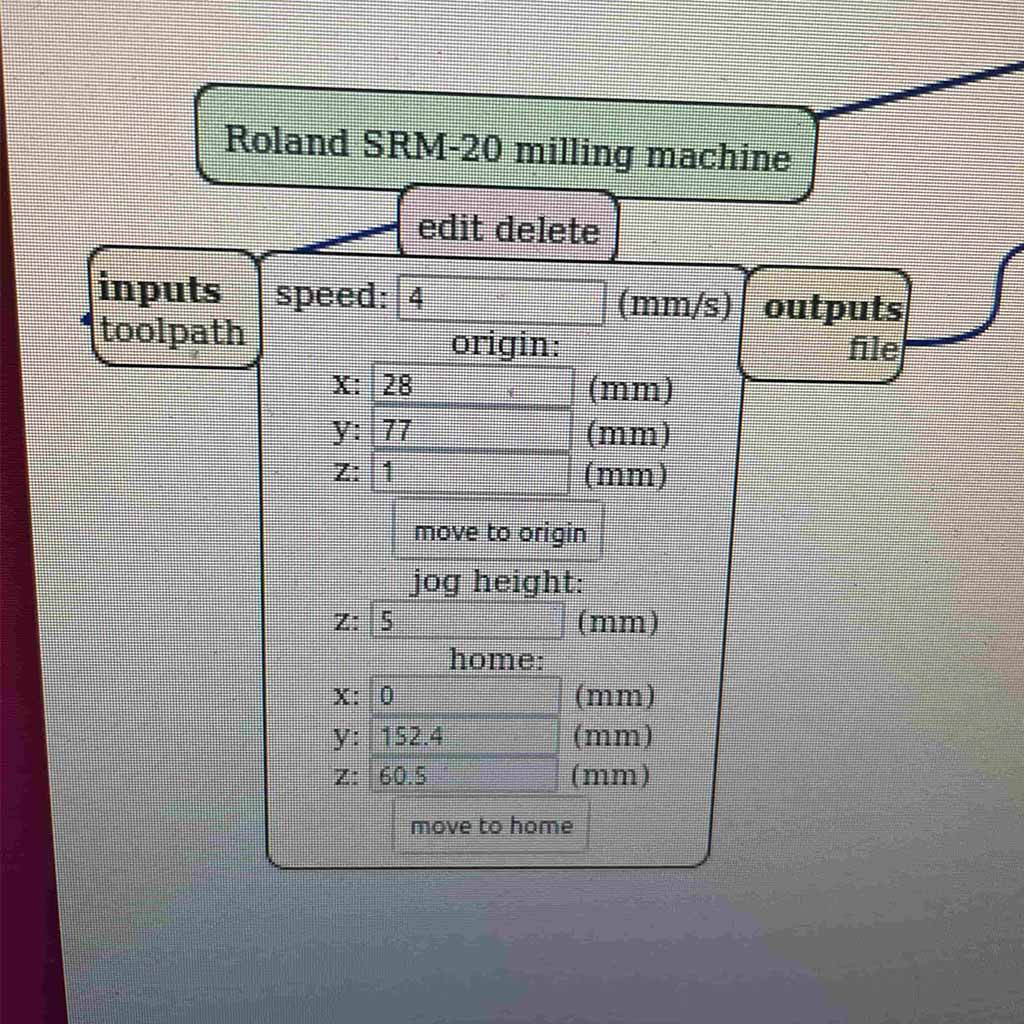
1.d. When I reached the right origin position for x and y axis (z = 1 or 2), I adjusted the endmill ir order to touch the copper surface.
1.e. Then, it was everything ready to run the first etching part (on Mods: 1/64 endmill > calculate > ensure port is open > send file to device)
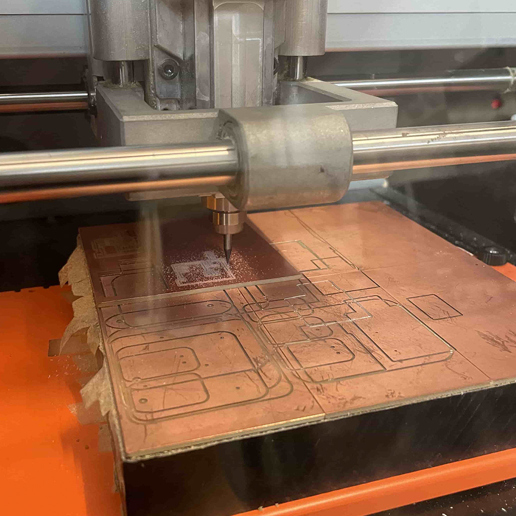
1.f. After etching, I removed the dust with the Festool vacuum and moved forward to cut the outline.
I repeated the process, changing for an 1/32 endmill and importing the outline .png image.
1.g. Finally, the circuit board was cut and ready to solder the components.
*Don't forget to put the endmill back in the tube and remove the tape from both the circuit board and board blank.
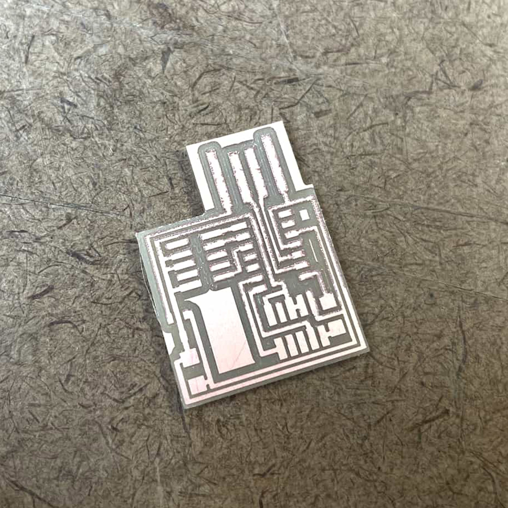
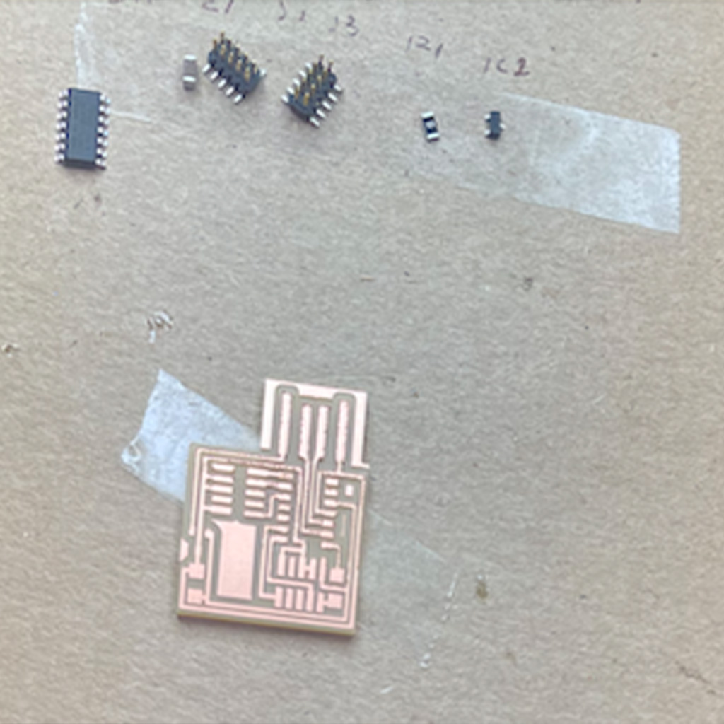
2. Selecting Components
2.a. For this PCB, the components were listed according to the image below
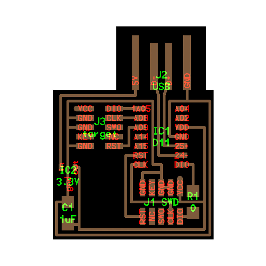
• IC1 D11C: Micro-controller
• J1 and J3: Connectors
• IC2 3.3V: Voltage Regulator
• R1 0: Zero-ohm Resistor
• C1 1uF: Capacitor
2.b. In the Arch Shop, the components are located by areas:
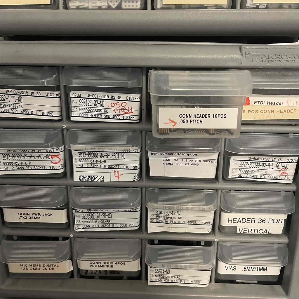
• Micro-controllers: Top part of the small wall
• Connectors: Bottom part of the smaller wall
• Resistors: Left part on the bigger wall
• Capacitor: Middle part on the bigger wall
• Voltage Regulator Right part on the bigger wall
2.c. After taking all, I positioned them on a cardboard with a double-faced tape to make the soldering easier and more organized.
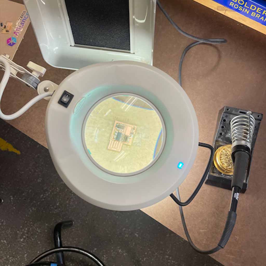
3. Soldering Components
3.a. First, organize the working space with everything you need (solder, wires, cardboard with components, magnifier, light and ventilation).
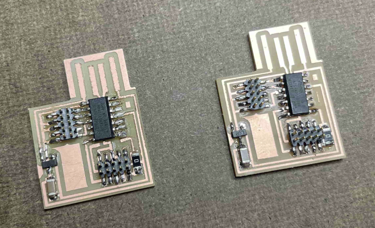
*I struggled a lot with soldering in the beginning. The first PCB has many parts connected that were not supposed to be connected. Also, after I finished I realized that the microcontroller was positioned upside down (the almost invisible circle in the micro-controller should be on the side that is closest to the USB connect).
3.b. With a new PCB printed, I started soldering using a better technique.
First, I applied a little bit of solder in a part of the board that should be connected to the central part of one component. This way, it is easier to handle the component with a tweezer on the left hand and attach it to the board.
3.c. After securing the component by one point, it is easier to solder the other connections. To do so, place the welding tool on the copper, wait for it to become hot and place the wire in the space between the component and the board. It will flow and connect them.
3.d. After soldering all components, I finnaly finished the printed circuit board.
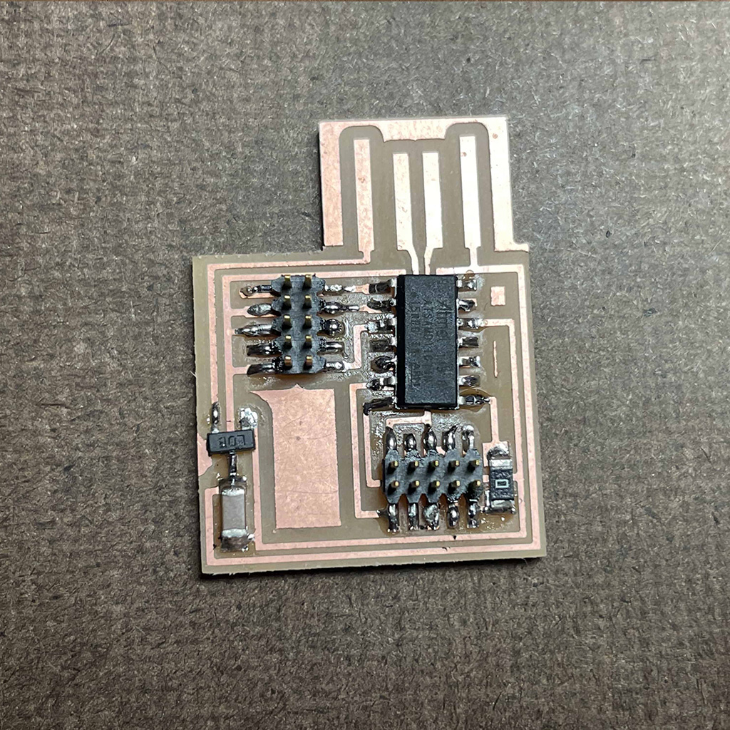
*Comparing with the first, the second PCB showed some progress. First, the soldering was not perfect but it was much better than previous one. Second, all components were in the right position. And finally, I noticed that copper traces were more clear, probably because I used a new endmill when etching it.
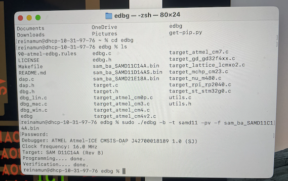
4. Programming
4.a. I tried to test the PCB on the computer, but the power was not working.
4.b. To debug, I used a multimeter to test all the connections between components. I found two of them that were not working because of a weak connection. In order to solve that, I reinforced the soldering.
4.c. Finnaly, the PCB turned on and everything worked well!