03
ELECTRONICS PRODUCTION
This week we worked on electronics production by milling copper to make PCBs (printed circuit boards).
| Tools: | Roland SRM-20, Soldering Iron |
| Files: | In-Circuit Programmer, Test Traces, Test Outline |
| Date: | 09.26.2022 |
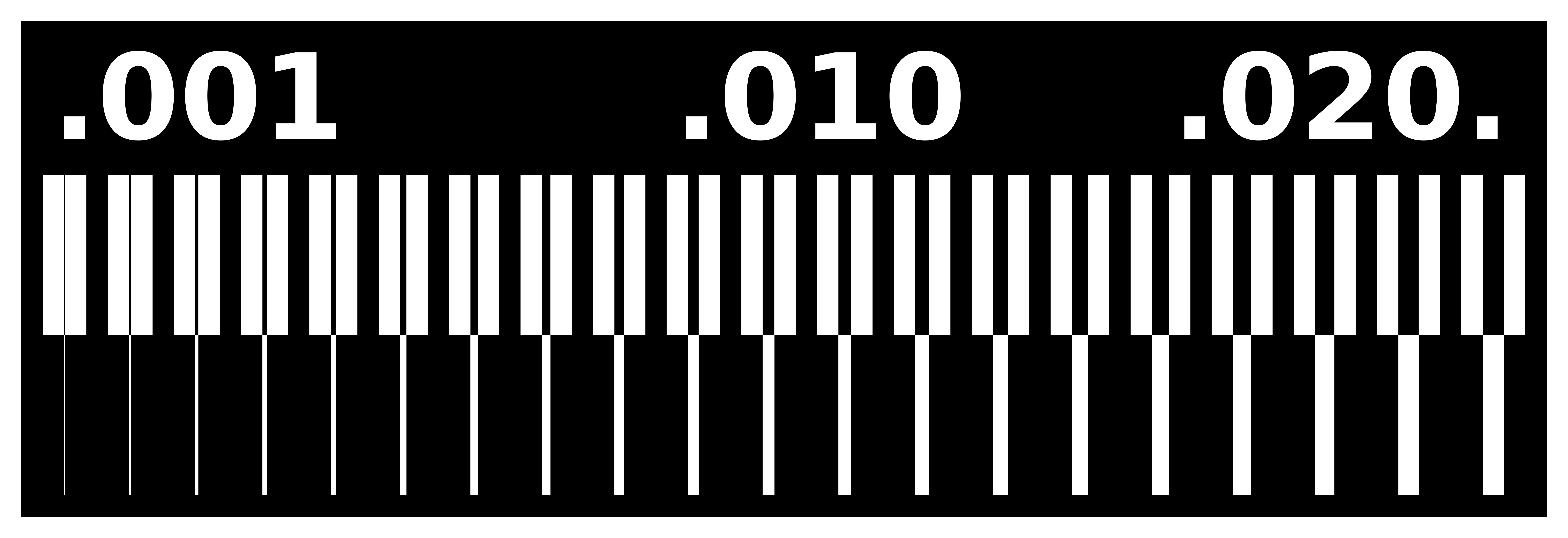
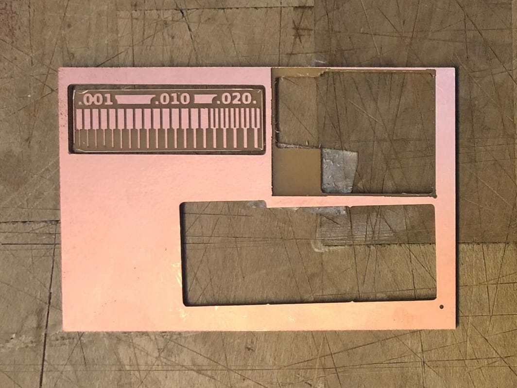
Mill Testing
For the group assignment, we had to test the milling maching and the endmills (both the 1/64" and 1/32") to check if they were in working condition. We used the Roland SRM-20 machine in the architecture shop. The result looked okay except for the lines thinner than 0.004mm--their thickness was not reliable and they were starting to peel off. Note to self: ALWAYS (!)remember to see if the board is taped down properly before vacuuming the inside of the mill or better still, remove the board before cleaning.
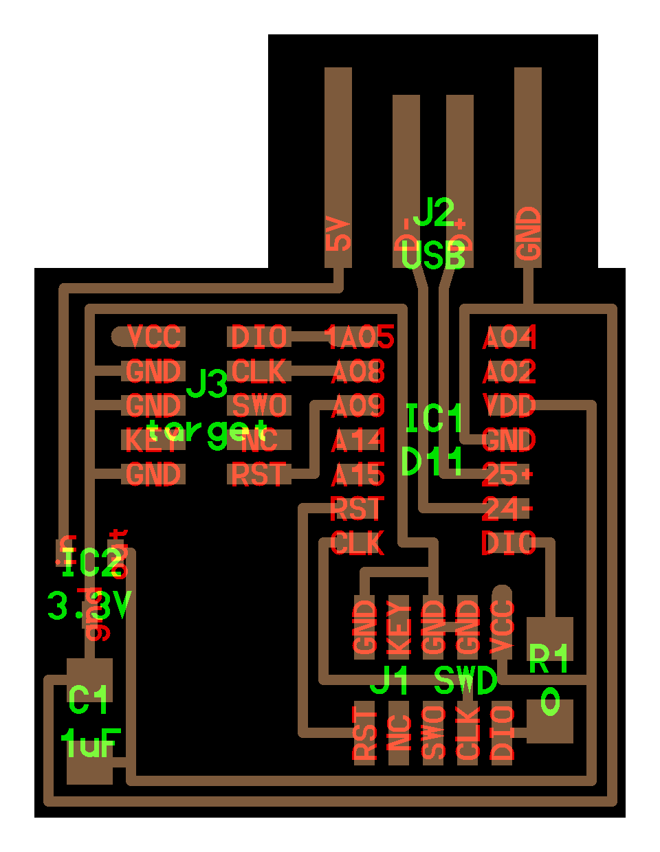
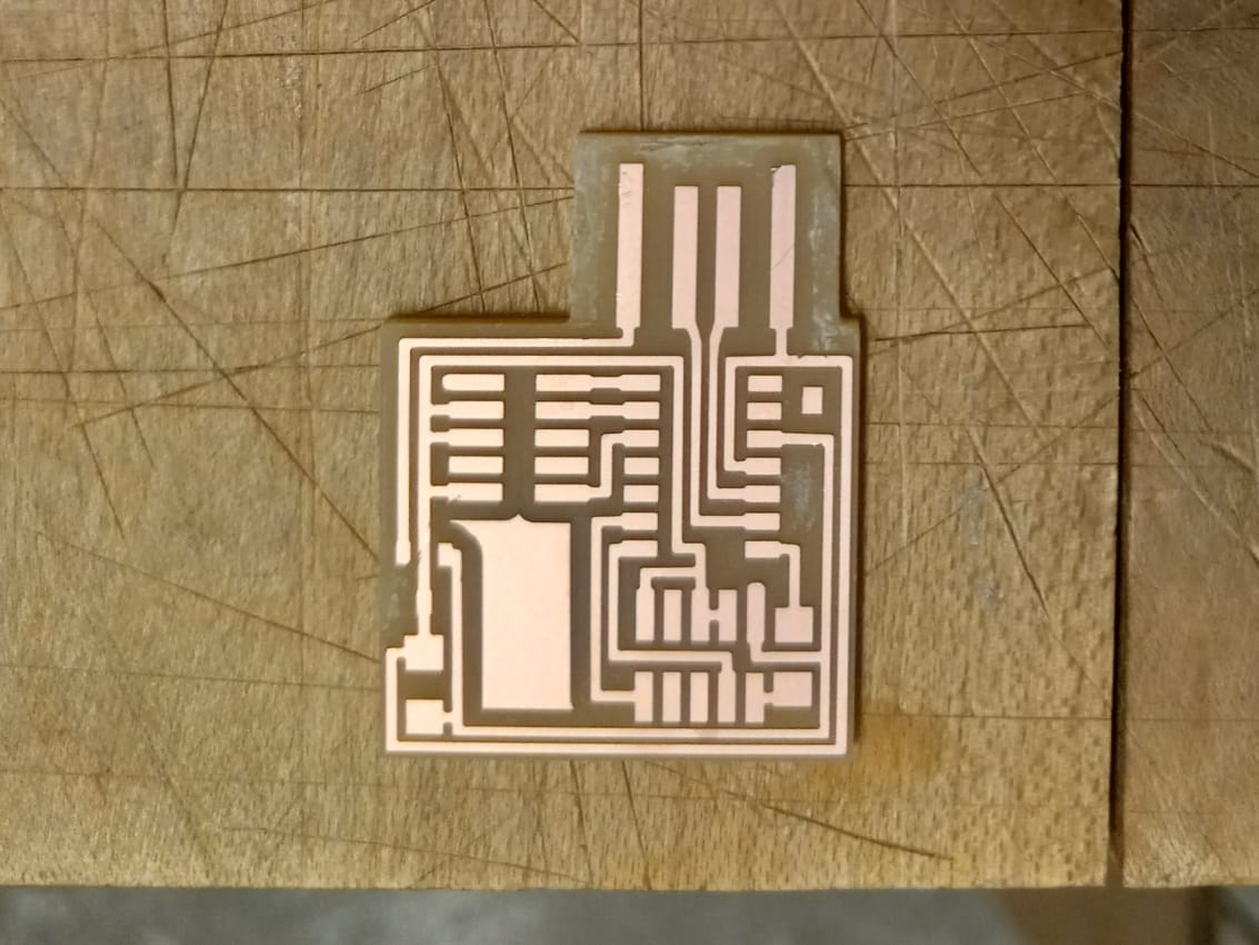
The Board
The week's assignment involves making an in-circuit programmer that includes a microcontroller. This can eventually be used to program other boards. I made the CMSIS-DAP.10.D11C board (shown below). At this point, I don't quite understand much of what is happening on this board. I focussed on reproducing it and am hoping to understand it's working in the future classes.
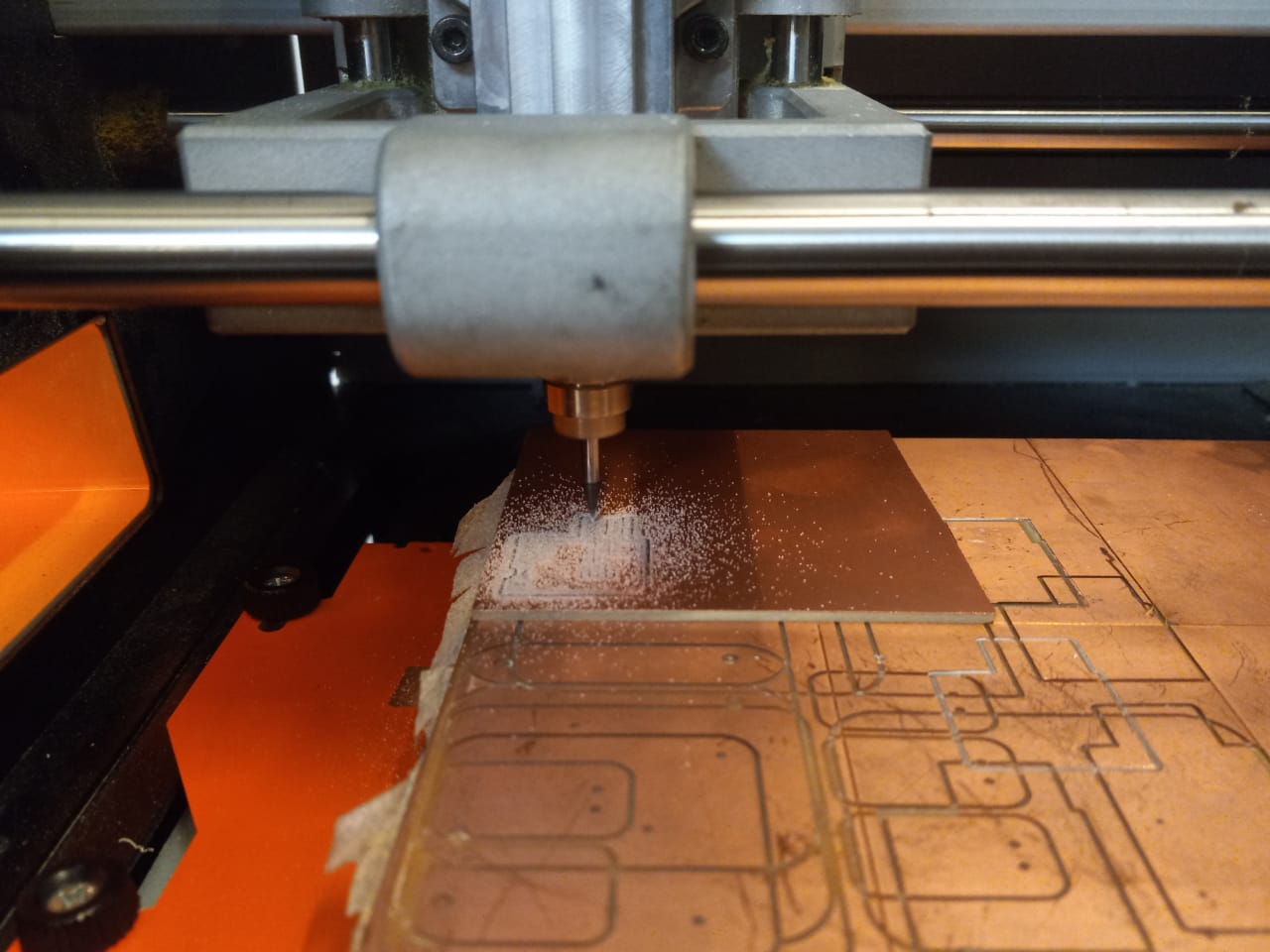
Milling
To mill this board, I used the png files on the Roland milling machine. For the traces (interior), I used a 1/64" endmill with an offset of 4 on mods. I could've used an offset of 0, but I saw that it was taking much longer. For the outline (cut out) I used a 1/32" endmill. Upon inspection, the board looked good. After milling the board, I removed the excess copper on the sides, sanded the edges a little, and washed it with soap to remove any dirt and oil.
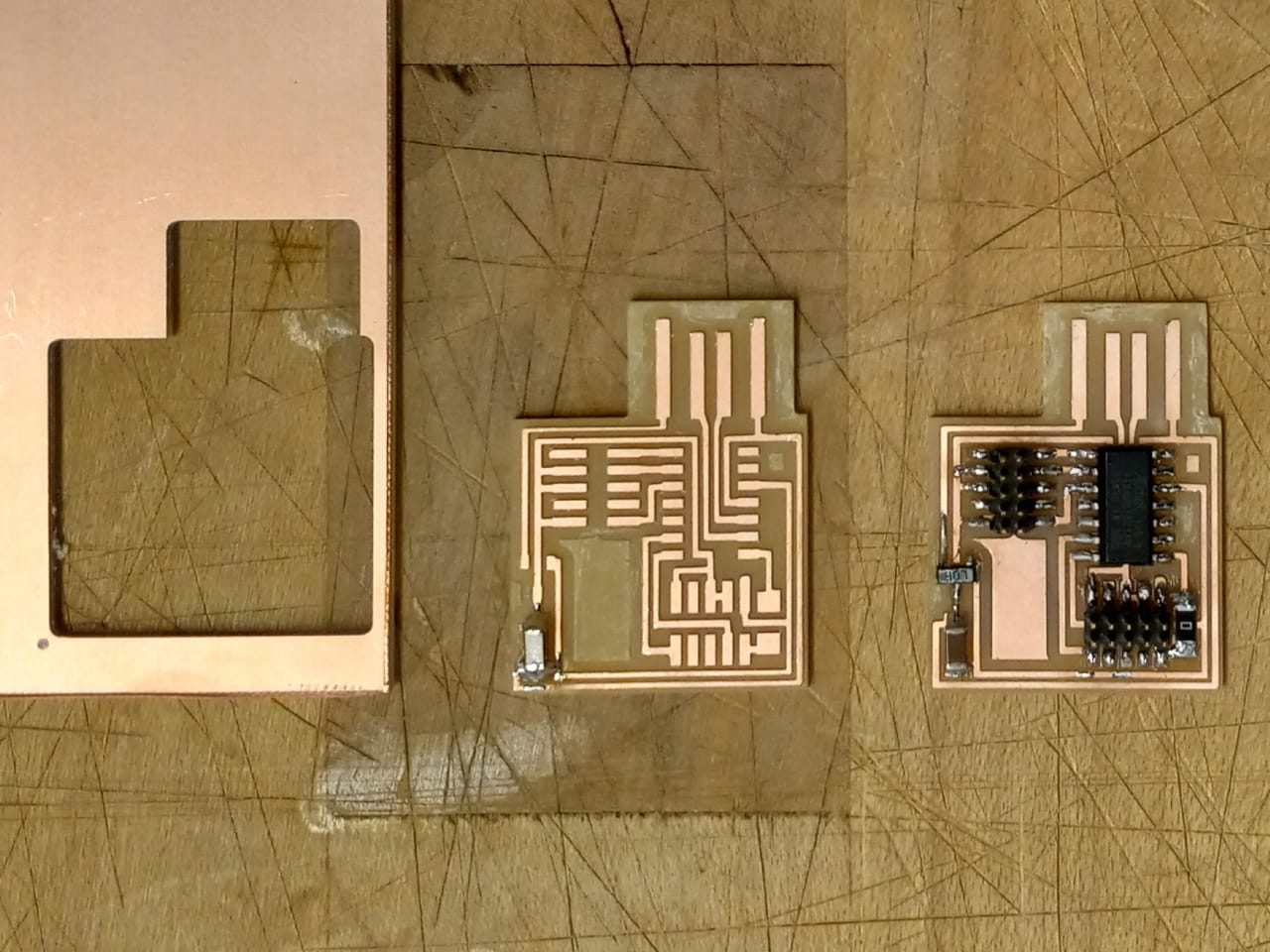
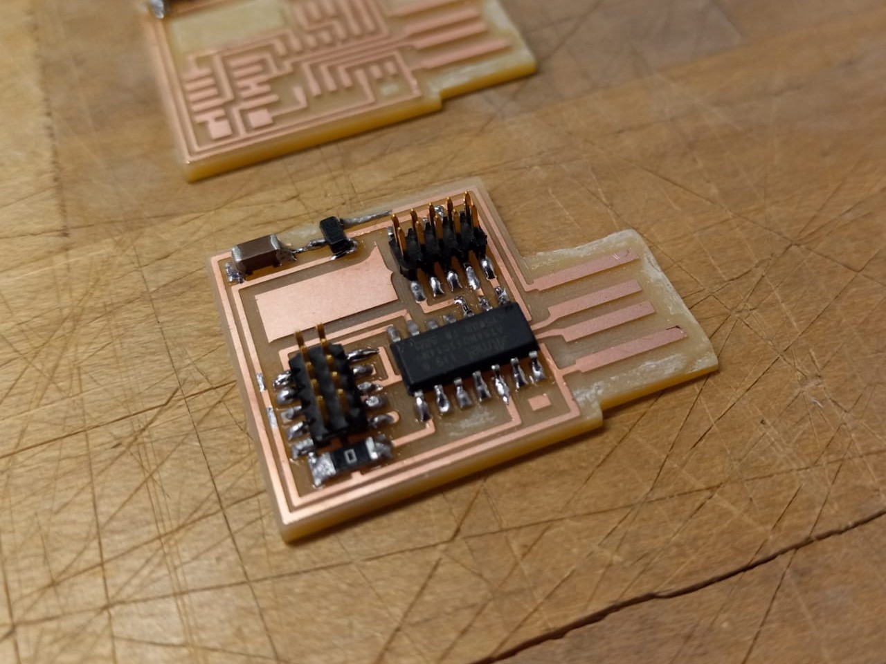
Soldering
The components to be soldered were: IC1 D11 microcontroller, IC2 3.3V voltage regulator, J3 target, J1 SWD, C1 1uF capacitor, R1 0ohms resistor. I used a rosin core solder (this does not flow as well as the lead solder) and set the soldering iron to ~750F. It helped to keep the soft coiled brass tip cleaner handy for constant cleaning. My first soldering attempt failed. The copper in the circuit came out entirely while trying to desolder using a copper braid. My second attempt was much smoother, resulting in the board below.
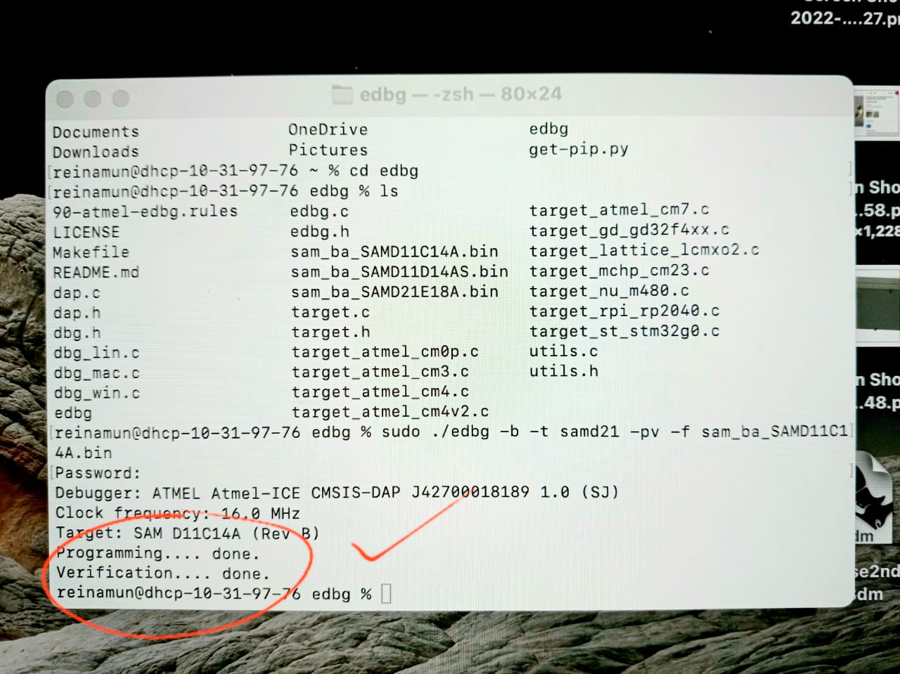
Testing
The TA helped me test the board. All worked well apparently. The board is ready to be programmed! The following image is proof of that. Again, I do not follow this testing process completely; hope to learn more in the coming classes.