04
3D SCANNING AND PRINTING
This week we worked 3D scanning and printing. Specifically, designing and printing objects that could not be made subtractively.
| Tools: | Sindoh FDM Printer (3DWOX1), Rhino, Revopoint Pop 2 Scanner |
| Files: | 3D Print File |
| Date: | 10.04.2022 |
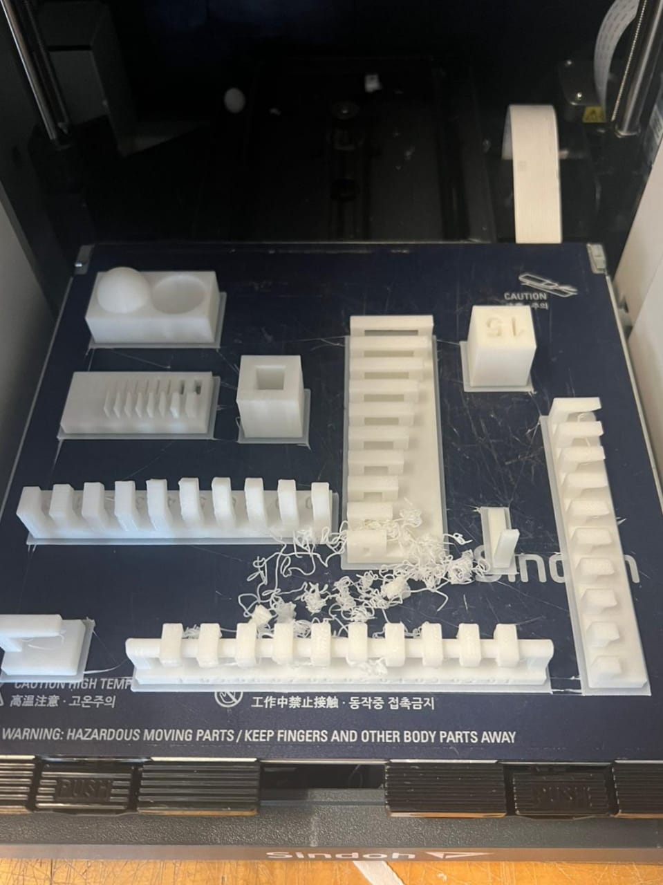
3D Printer Design Rules
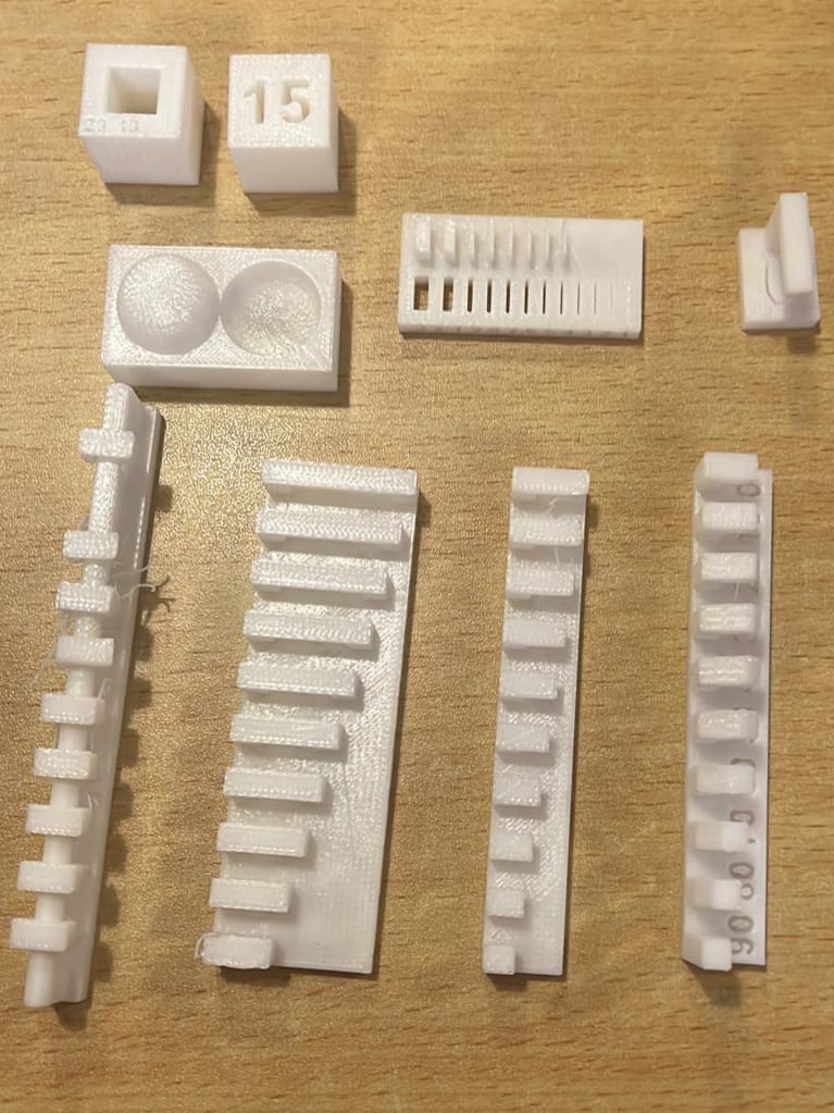
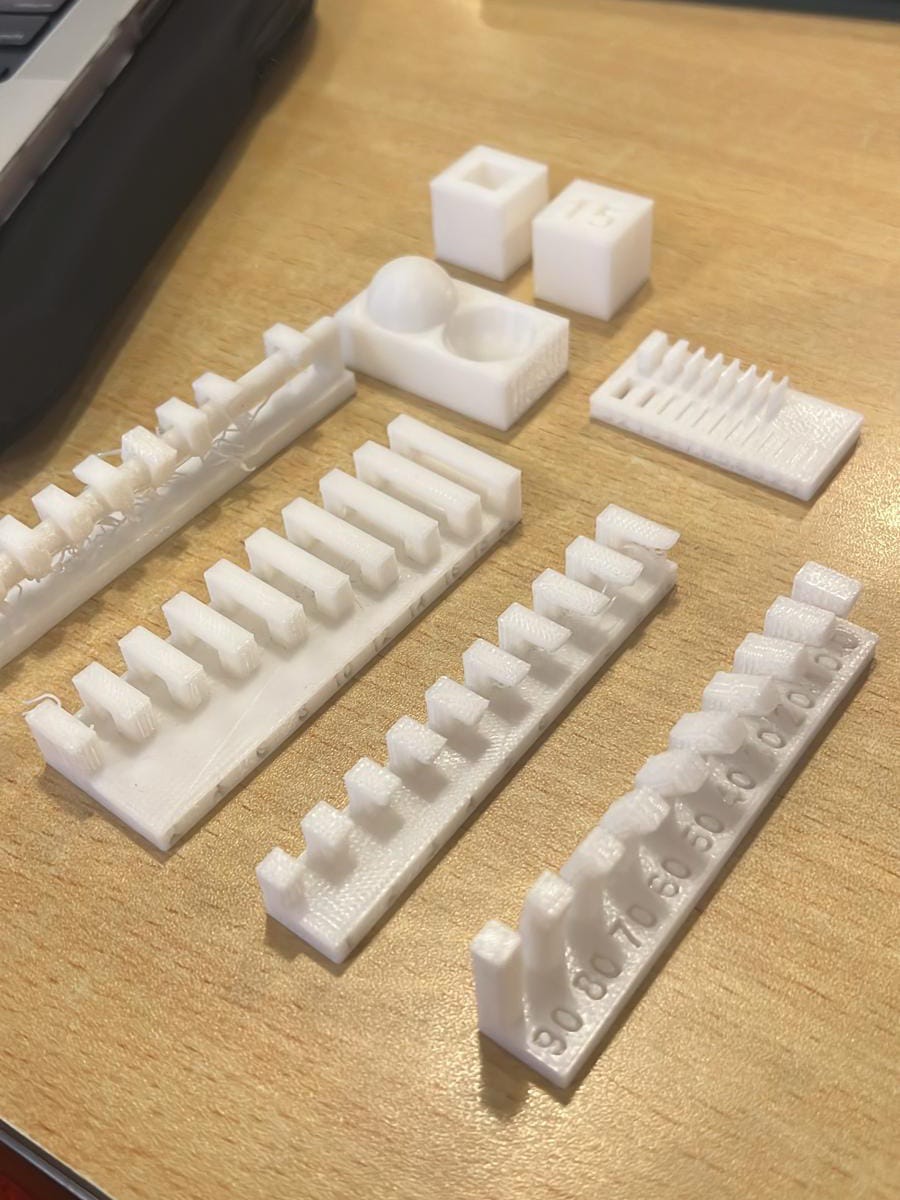
This week's group assignment was to test the design rules for our 3D printer(s). We printed a few test prints, each characterizing a different aspect of the Sindoh SDM printers. The objects testing the overhang show how supports are necessary for long overhangs, and overhangs above 1mm without supports result in sagging material. The object testing the clearance shows how a minimum of 0.3mm of clearance is necessary for separation between between features. The overhangs test shows how we can print successfully at an angle above 20 degrees without supports. The bridging test shows the printer can successfully bridge various lengths with minimal material sag. We further tested wall thickness, embedding dimensions, anisotropy, surface finish, and infill with satisfactory results.
Designing and CAD Modelling
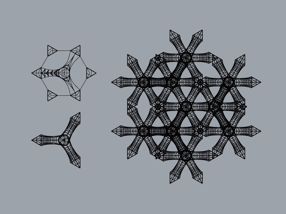
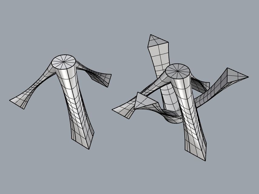
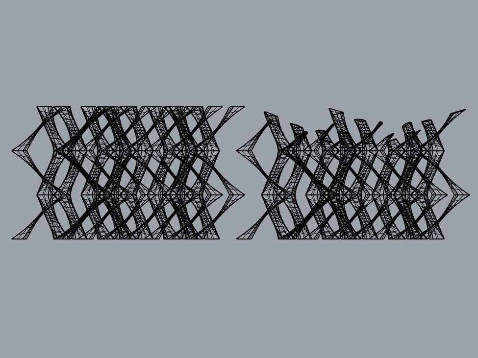
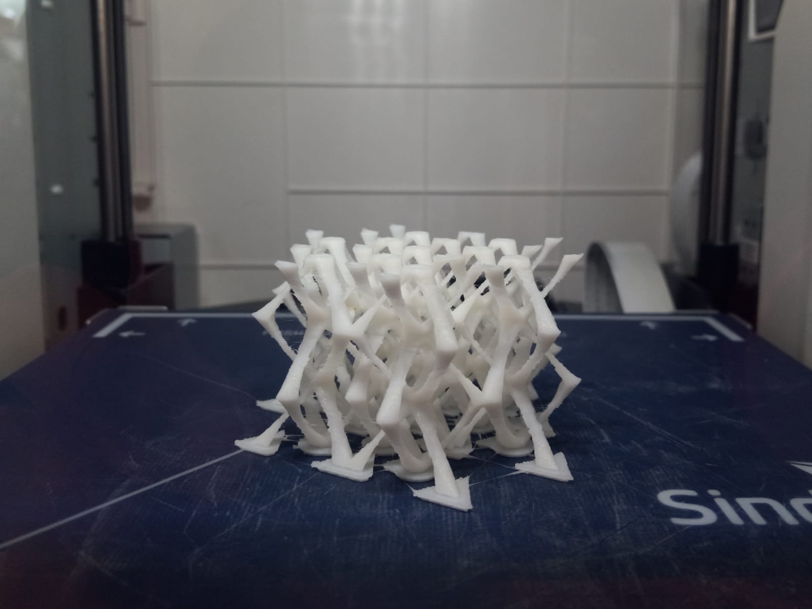
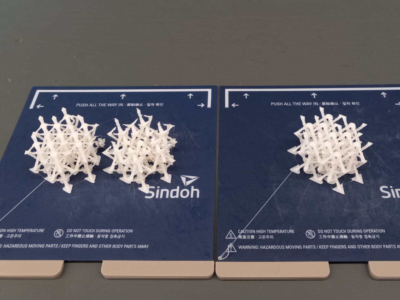
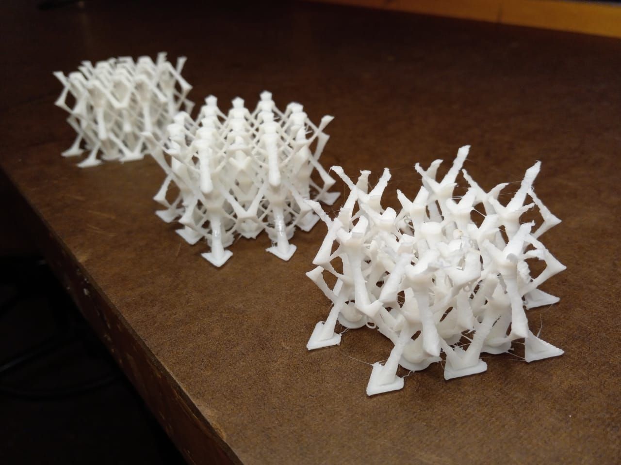
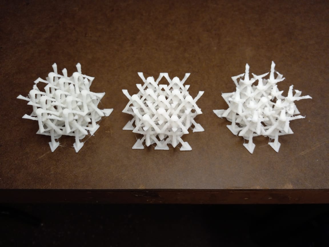
The week's assignment involves designing and printing an object that necessitates additive manufacturing. This prompt inspired me to explore making intricate features with varying cross-sections (in all directions) and interesting negative spaces. I thought an aesthetic inspired by biomimicry would best allow this, but I felt restrained by my CAD/programming abilities to produce a generative design. Inspired by this past htmaa project, I designed a lattic-like, modular structure. Instead of using circular cross-sections (along the Z-axis) I chose to use triangluar cross-sections with the belief that edges will add more inticracy to the result. I used Rhino for CAD modelling. As an experiment, I used a doubly-curved surface to slice my lattice to see what kind of geometry it would result in. Convinced that it is interesting enough, I decided to print this as well.
Processing Files
I proceeded to export to STL. Setting the tolerance to 0.01mm for the objects, each spanning about 7cm, resulted in a relatively heavly file (40mb). I also created another STL file with just the original object (not sliced) and a tolerance of 0.1mm. This resulted in a much lighter file (7mb) and is the one linked above. I generated gcodes for both files using the 3DWOX software. Because all my overhang angles were greater than 20 degrees, I did not use any supports. I added rafts to ensure better adhesion to bed.
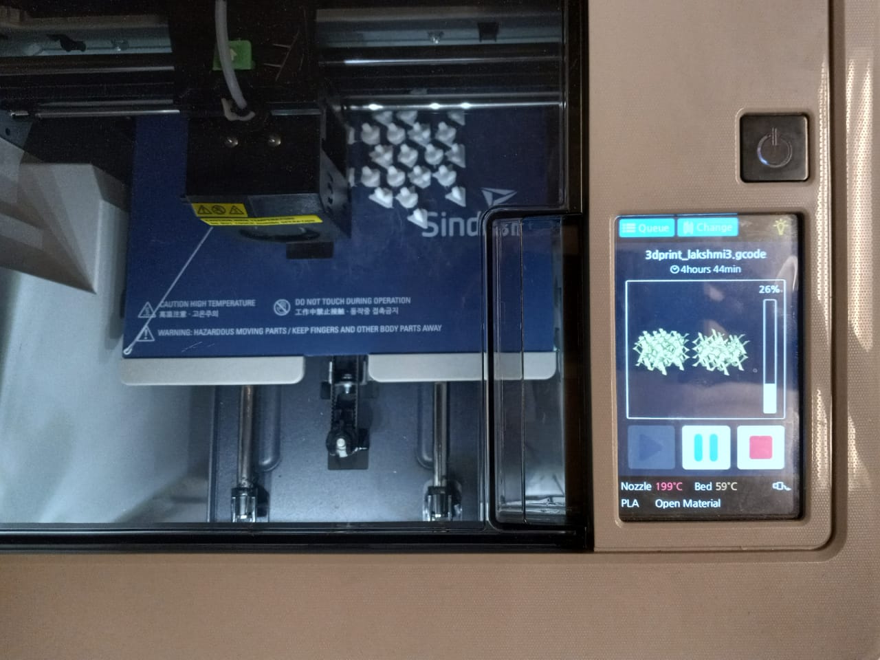
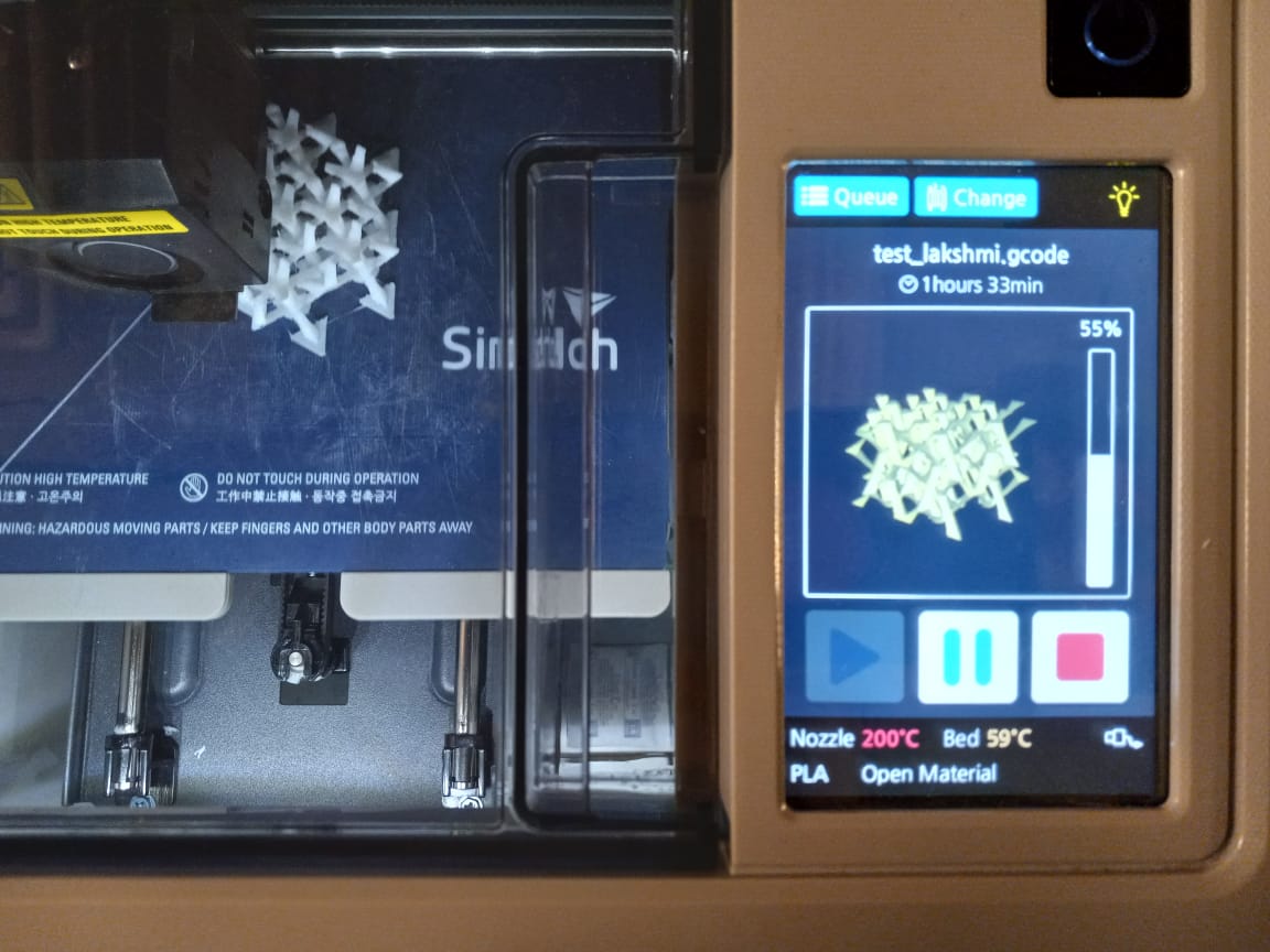
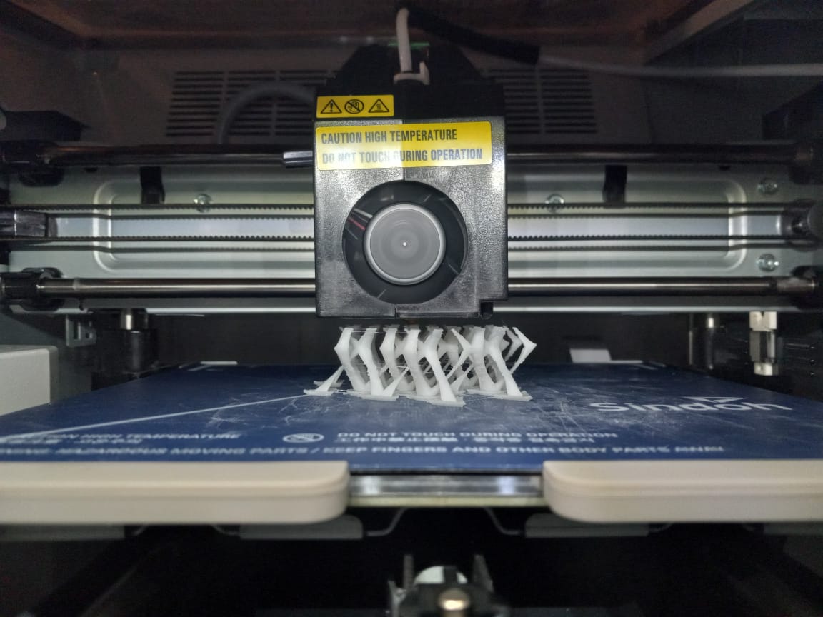
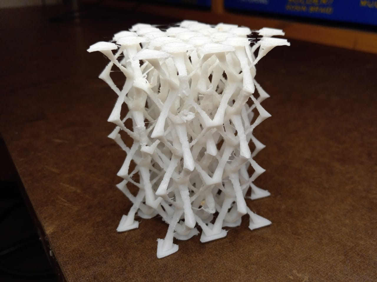
3D Printing
The process took 6hrs 30min for the larger file and 3hrs 20min for the lighter one. I'm not entirely satisfied with the results. Some of the pieces broke while trying to remove from the bed. I tried cleaned the objects using an exacto knife to get rid of excess filament but without much success. Since the components had varied cross-sections, some just about a couple square mm, the STL file with a tolerance of 0.01mm resulted in a more structurally stable object. It would be better to scale up the objects for stronger results.
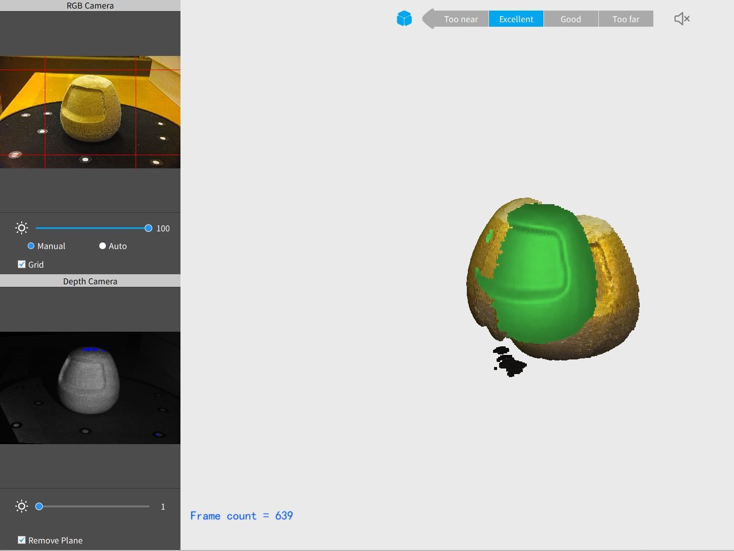
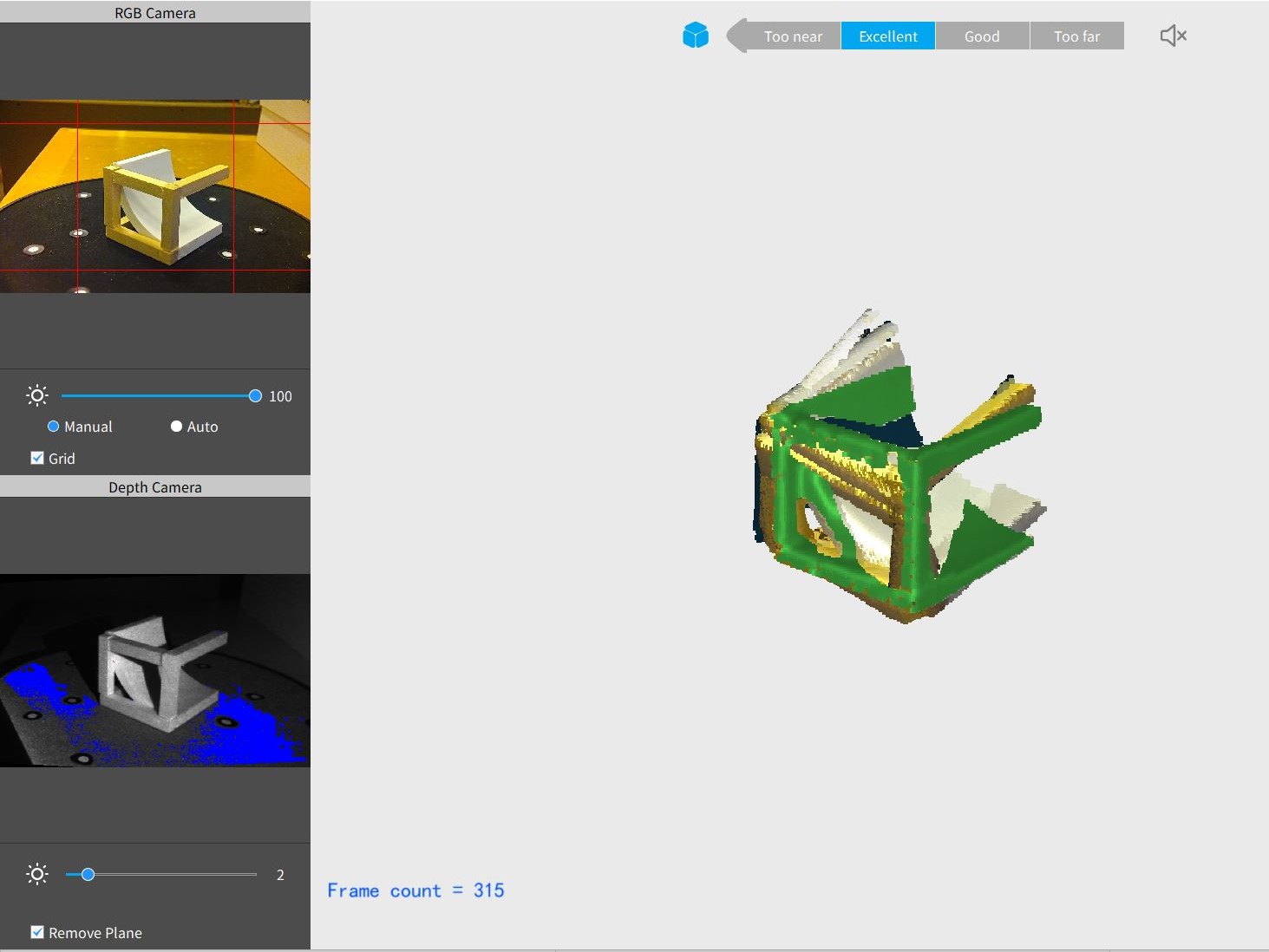
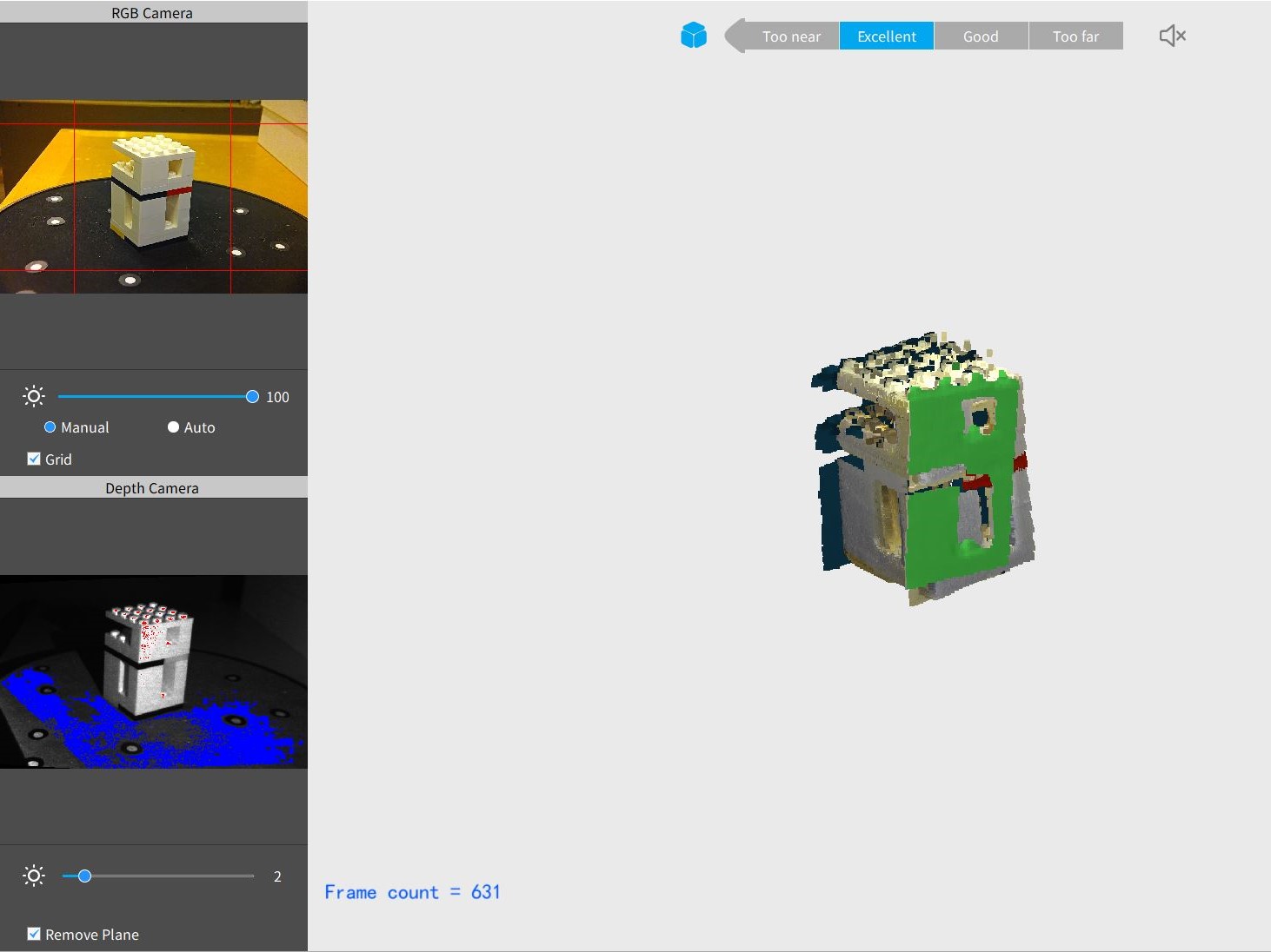
3D Scanning
I set up the Revopoint Pop 2 Scanner for scanning a few small objects. The results were very frustrating. I put the objects at the centre of the rotating bed with the point cloud. Although the distance showed "Excellent", the scanner kept losing track of the object, recreating it at a different angle for every ~1/2 turn. The following screenshots document some of the attempts. I tried with objects of varying colours and reflectivity with no success.