06
COMPUTER CONTROLLED MACHINING
This week we worked on designing and making something big.
| Tools: | Rhino, Mastercam, Onsrud, Woodworking Tools (Rasps, Band Saw, Table Saw, Handle Jigsaw, Festool Sander, Wooden Hammer, Clamps) |
| Files: | Desk Model, Desk Parts Layout |
| Date: | 10.18.2022 (update: 12.01.22 |
Group Assignment
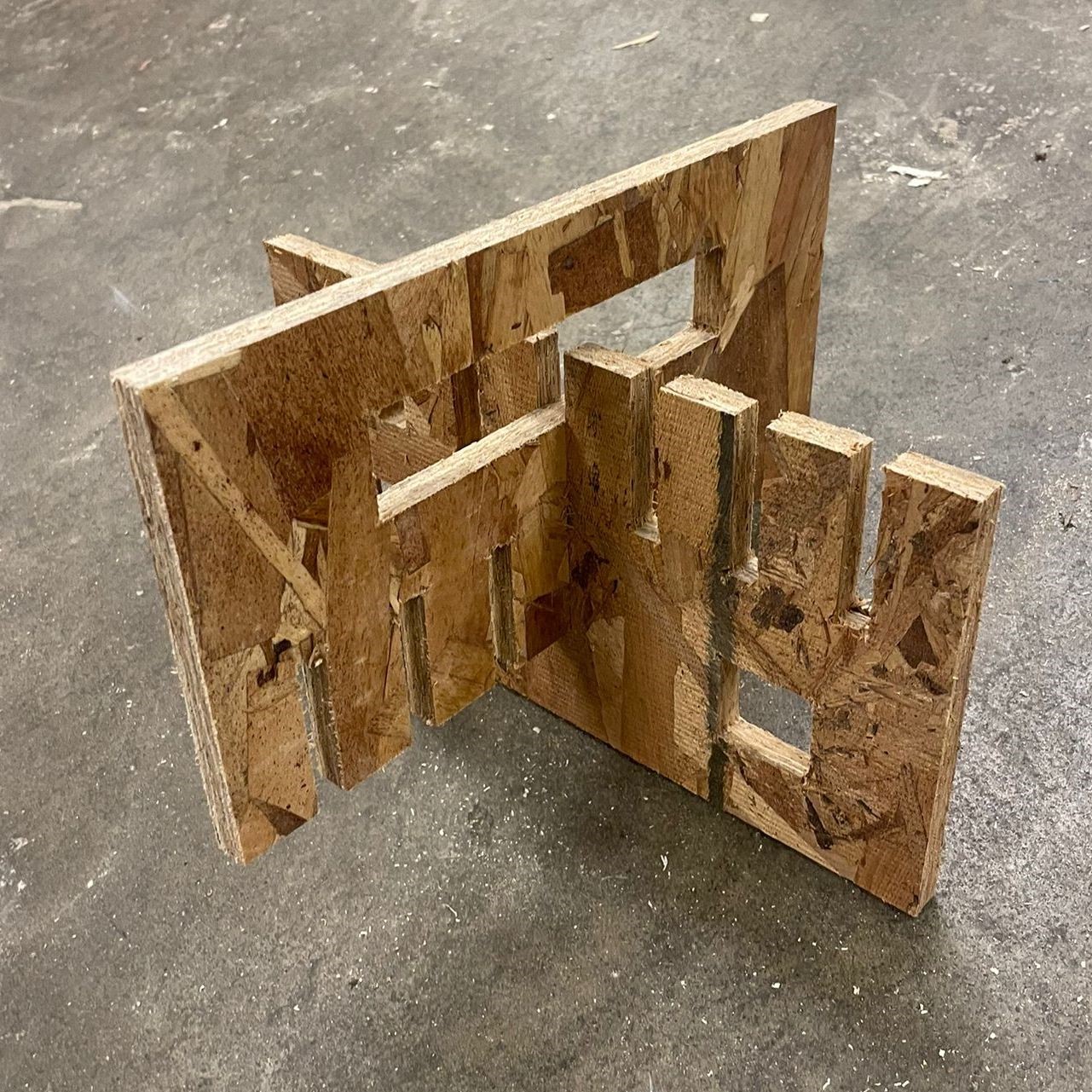
A group of us did the safety training and test cut with Chris at N51. Chris showed us some of the settings in Mastercam and described how we need to set points at the inner corners in a separate layer to create multiple toolpaths--one for the corner holes, one for the outline cut, and one for the remachining cuts around the corners. Chris also adjusted the onion skin from 0.008" to 0.015" because he had cut into the spoil board earlier in the day. Then we cut the test cut which had slots at different widths so we could see which ones fit best. We looked at the animation of the job to make sure the toolpath looked correct. Then we ran the job to actually cut the board. During the job, Chris adjusted the feed rate to show how it sped up/slowed down the cutting process. Finally, the pieces came out of the board pretty easily even though Chris made the onion skin thicker. We tested which slots worked best to create a snug fit. The cut widths of 0.42" and 0.46" both worked well enough, though 0.42" needed much more force (a hammer) to actually fit the parts all the way whereas 0.46" was much too easy. I would end up choosing 0.42" for my own assignment with the idea that a tighter fit would allow more stability and strength and that I would always be able to sand the edges down if necessary. This decision would later torment me!
Ideation
My room in my current apartment does not have a lot of space, so I've been on the lookout for multipurpose furniture for a while. This assignment felt like the best opportunity to build a custom piece of furnishing for my room. So I planned to make a wooden standing desk combined with a shoe-rack (or a book-case depending on need).
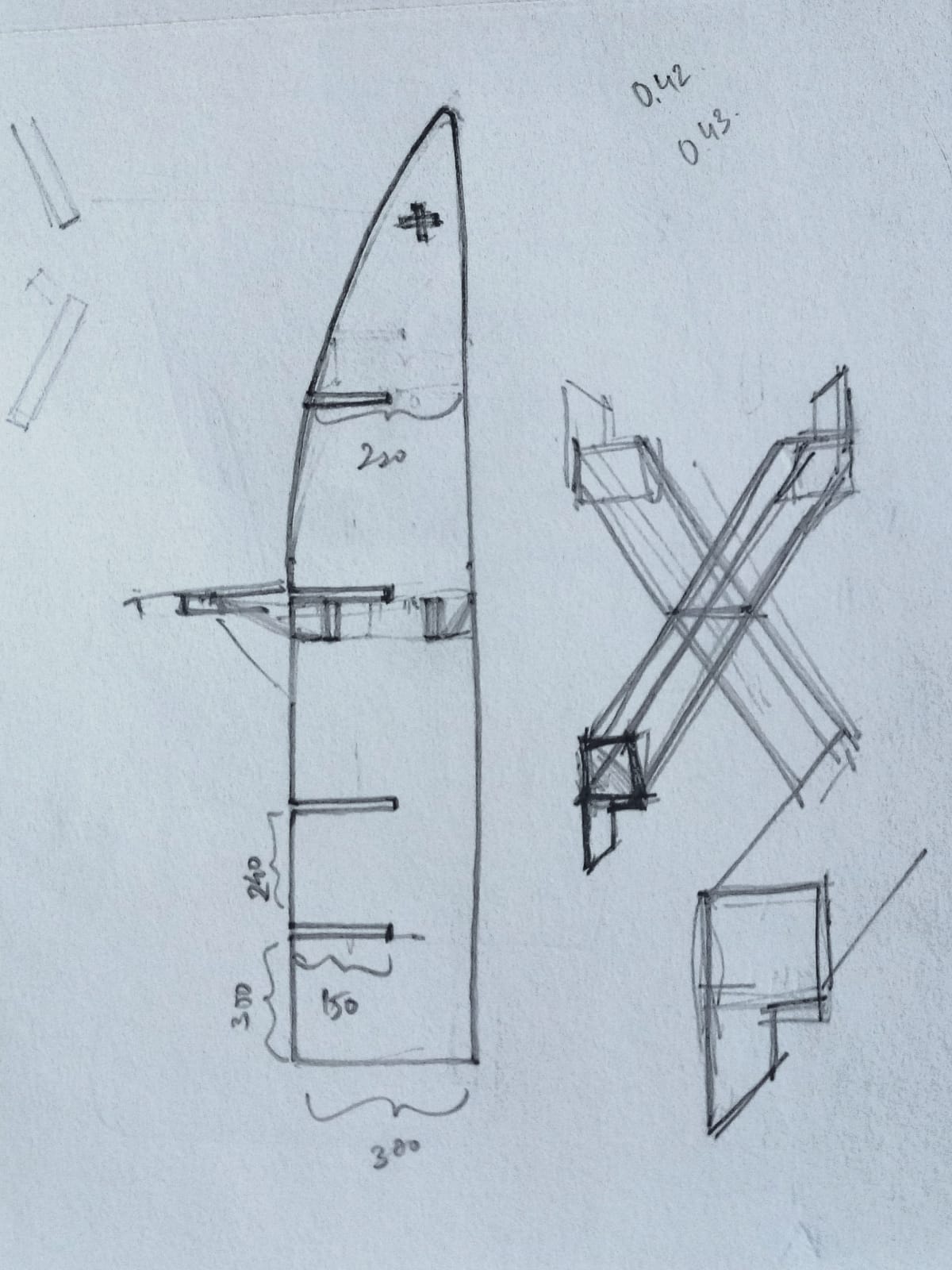
For a start, I took my height measurements (with and without shoes) for the level of the primary desk surface as well as the level for a secondary surface to mount a potential monitor. I combined these with anthorpomentric standards for shelf depths and width to then design the standing desk/shelf.
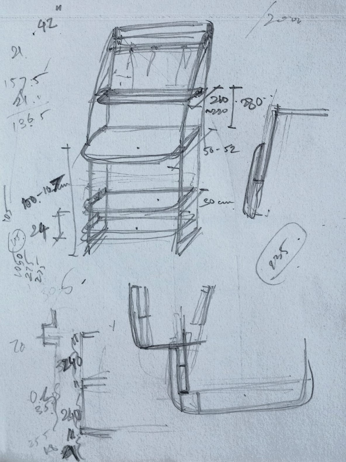
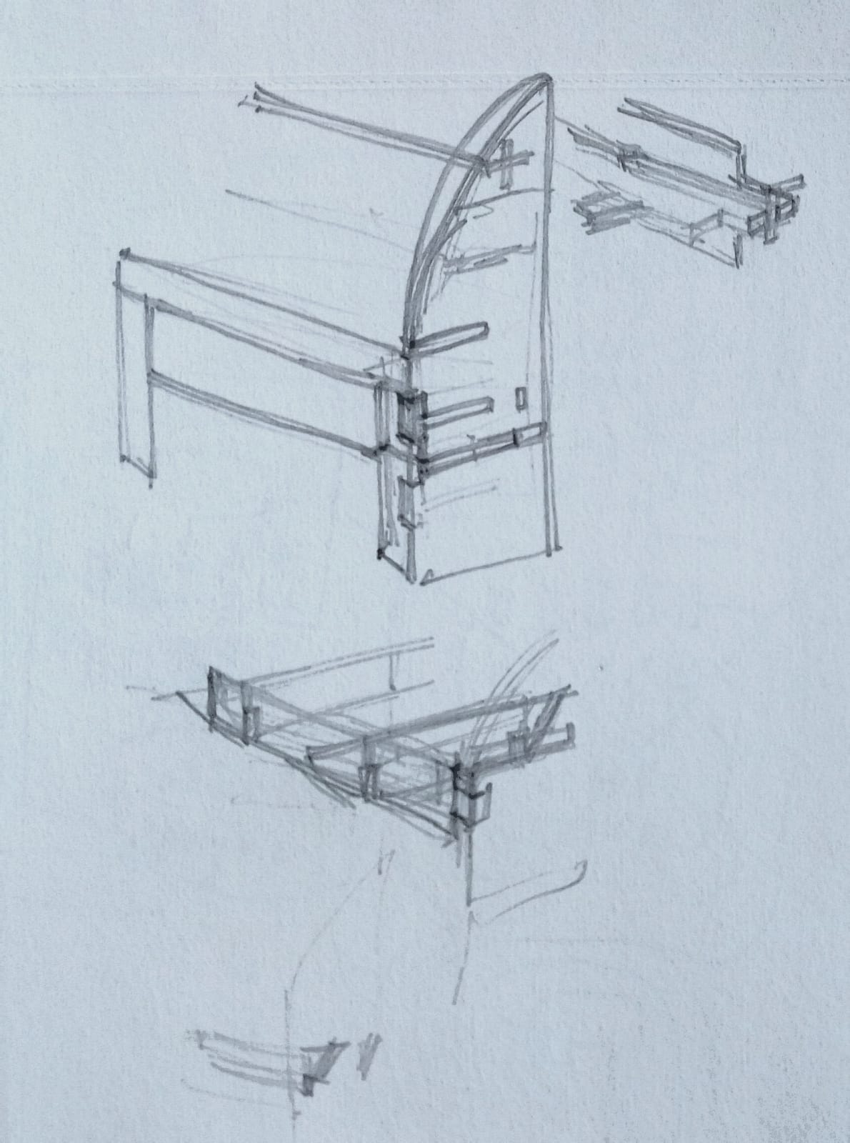
Design & CAD Modelling
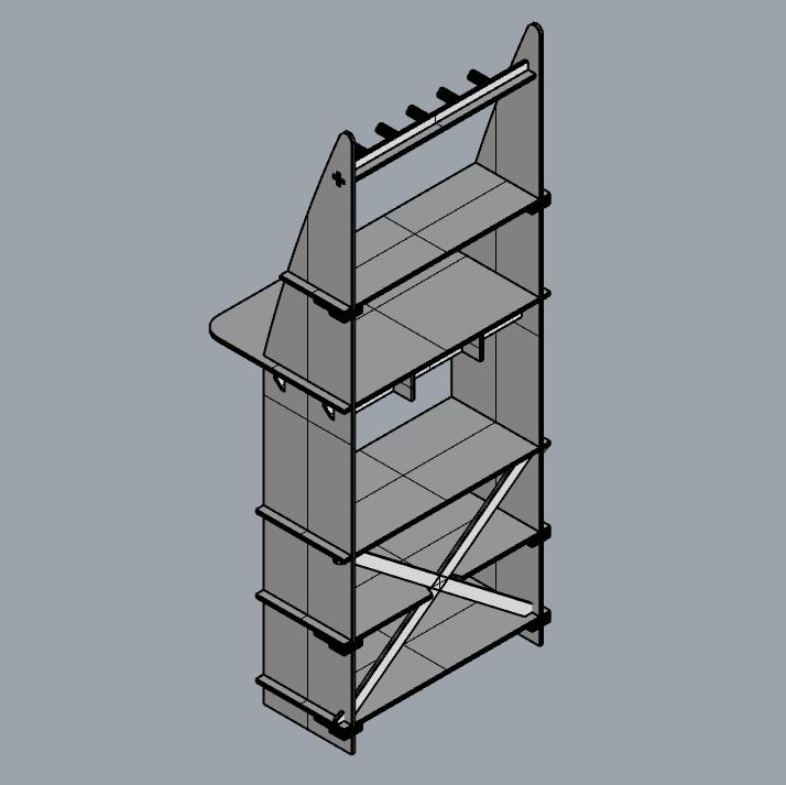
The whole structure is designed to be assembled entirely through wooden joinery, without the need for any glue or nails. I mainly used halved press-fit joints in the design along with a few mortise and tenon joints.
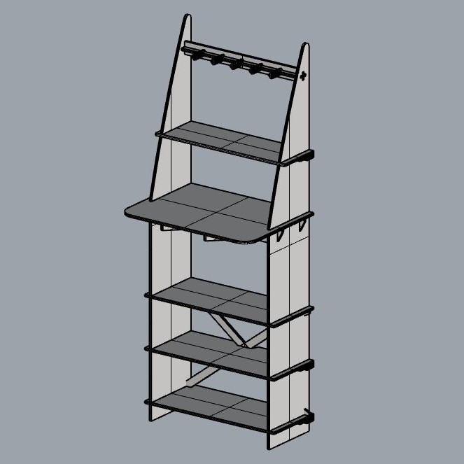
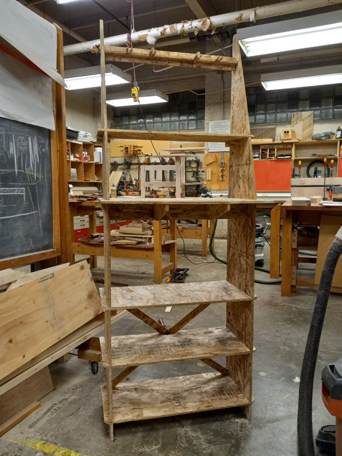
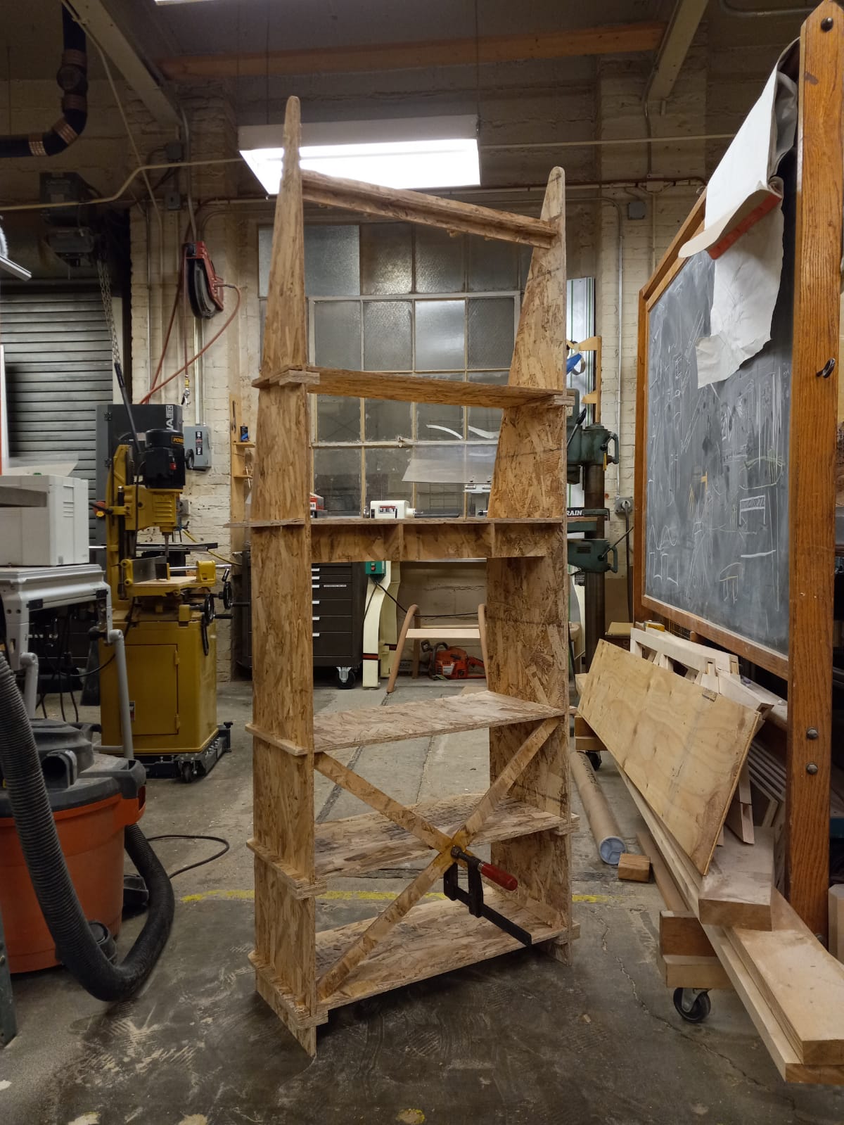
My original design of the desk did not have the cross-brace in the back as shown in the picture below. Chris (from the architecture wood-shop) suggested that I would need a brace to add stability to the structure. Given the height of the frame, it would not be very strong against lateral forces and a cross-brace would help strengthen the frame and keep it from wobbling. I added the brace with a cross-lap joint to fix this issue. However, I did not spend much time figuring out the process of assembly of the various parts and this would later lead to me spending many hours trying to bend and twist things into place.
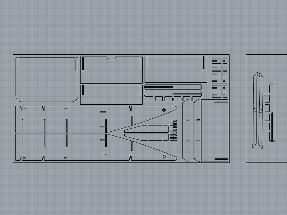
Parts Layout
All the necessary parts fit in the 8x4ft OSB sheet, except for the brace. I used left over board from other jobs for these parts.
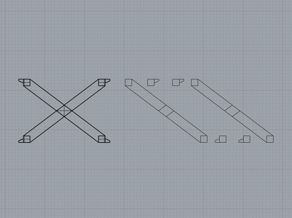
In a hurry to proceed to the actual cutting, I forgot to check the orientation of the parts for the cross-brace. The parts are merely mirrored, so the cross-lap would not fit in the right way. I later tried to make the part myself using a band saw; Chris helped carve out the lap joint. This attempt was also botched when the parts broke during assembly. Finally had to machine them again with multiple lap joints (I made peace with the reduced structural strength this would cause) so that I could assemble the brace in parts. (Even this final machining wasn't problem-free. The orientation of the board on the Onsrud was different from that on Mastercam. Thankfully I caught this before any potential damage.)
Gist: Check layout of parts, especially those involving lap joints! With structures including assembly of parts in various directions, have a plan for the assembly! Watch the Onsrud carefully!
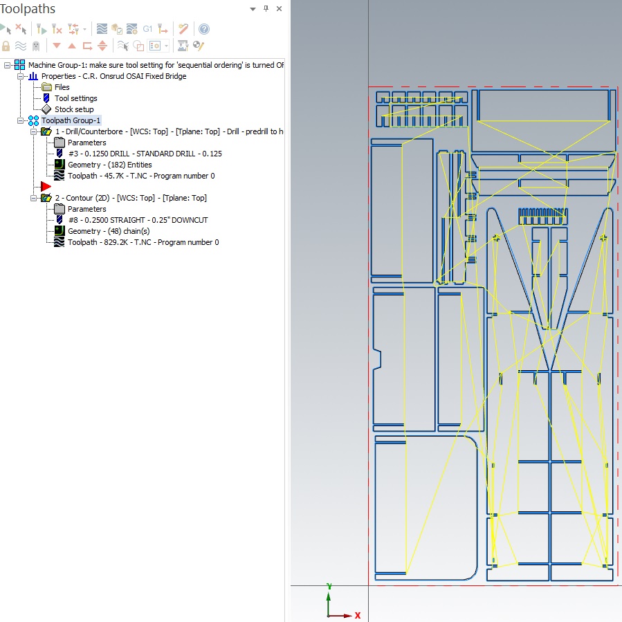
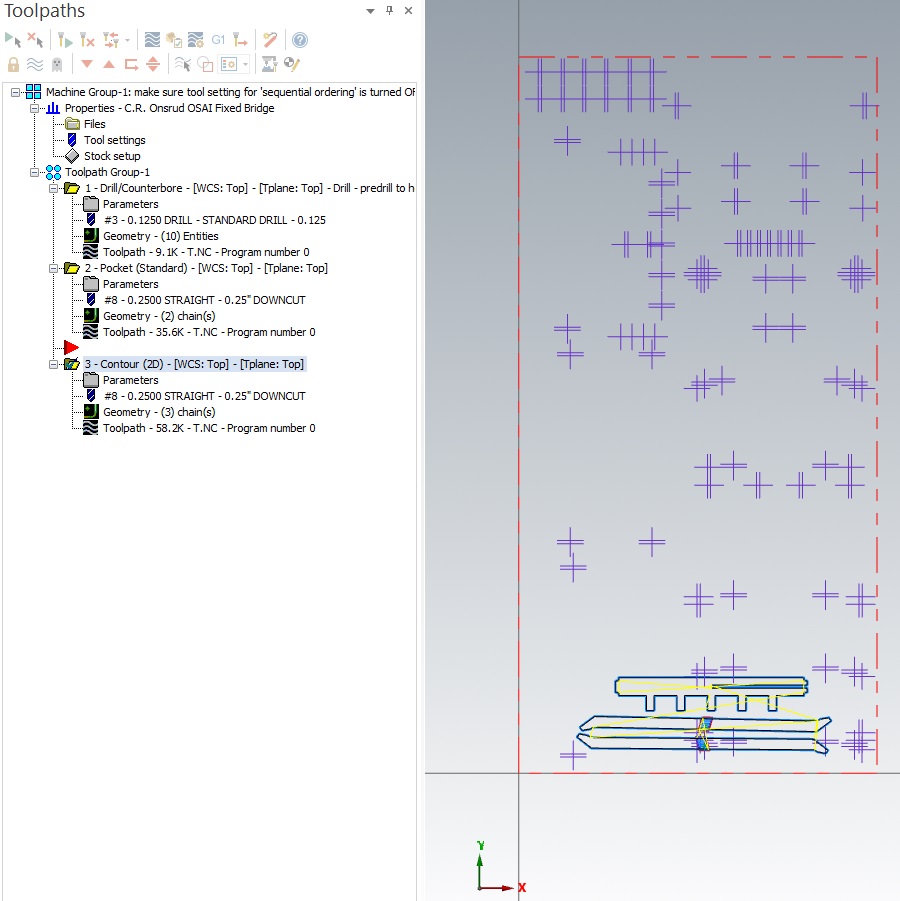
Mastercam
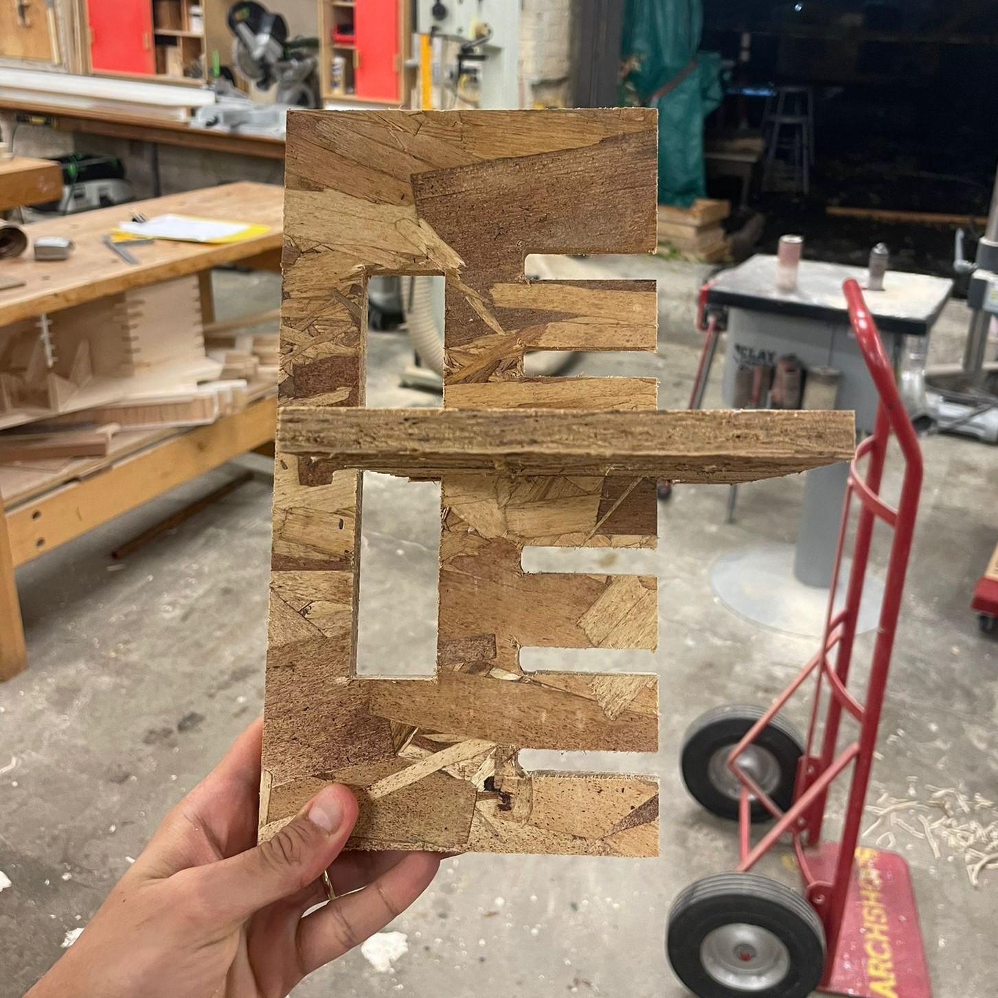
I set up the full-cuts on one layer. The cross-lap joint with half-depth cuts on a second layer. And the points for vertices at inner angles (less than or equal to 90 degrees) on a third layer--these points locate where a bit (of optimal radius) would need to drill into the board so that I would not have to sand out the fillet left by the cutting bit. The press-fit joints with these drill holes end up looking like mickey mouse.
Because of the aforementioned saga involving multiple machining takes, I saw Chris and other shop monitors set-up the files a few times. I started to get the idea of Mastercam and the basics of it. We left an onion skin (0.008 again because of learnings from the previous jobs) on all the jobs to keep the cut parts from coming lose. We also had to set the direction of the chains, because Mastercam cannot tell what's negative space and what's positive.
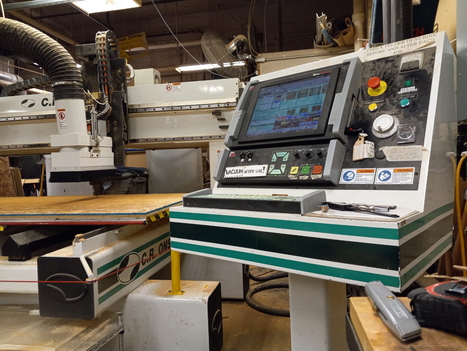
Machining
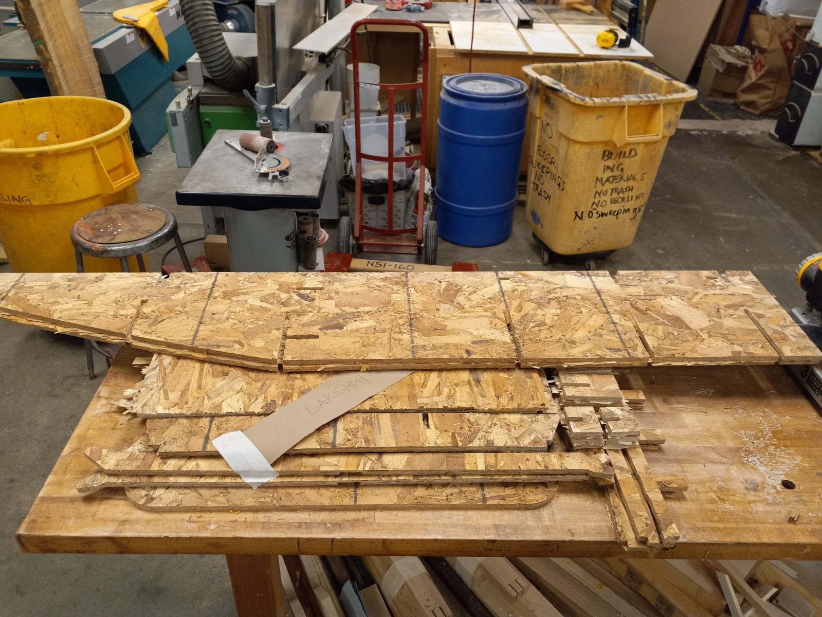
The Onsrud is an impressive machine! However, there is little room for error so I spent a lot of time watching and listening to the machine while it cut through the obscene material (I have no affinity for OSB!).
After machining, the OSB parts were still attached to the onion skin and needed to be cleaned with rasps and sanders. The particles of the material chip and break often, thus needing gloves for handling. The processing of the OSB parts was time-consuming, especially because I was planning on using the desk regularly and was concerned about the finish. Treacherous edges would surely make the desk hostile for working on.
Assembly
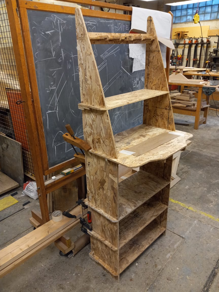
OSB is painful to work with. It is not a reliable material. The board did not have consistent thickness and the conditions of the surroundings were sure to further change its properties. I settled for 0.42" for the width of the joints based on the group test. This was a mistake. Though smaller parts responded well to coercion, I had plenty of deeper joints where the parts went in half way and then got stuck. At this point, it seemed like work both to continue persuading the joints into place or to remove them and sand the parts before trying again. I tried both versions of assembly, but more frequently resorted to brute force with the hammer (I blame this on later hours and impatience). Hammering OSB edges is a bad idea! I ruined many surfaces and edges this way, hoping to later sand out the mistakes. But the corners of main desk surface with the deepest joints suffered considerable damage. I then proceeded to use a hand-held jigsaw to cut out the edges in the shape you see below (not bad at all!). This together with the assembling of the cross-brace and re-sanding (after hammering) took the most effort. The peg rail at the top of the desk was also hard to fix. It kept falling down which made me wonder if a cross-brace at the top would also have helped to keep the width of the space constant and lock the rail into place. Or I could've used longer tenons. For now, I let it be; it only falls when heavily disturbed.
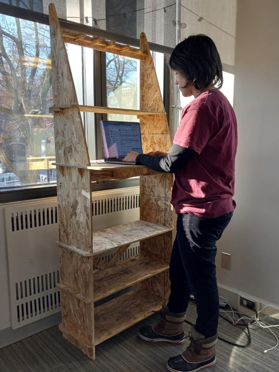
After many many hours of struggle, the parts all came together in the form that I imagined them in. More or less. Some of the surfaces were bent and were splaying at the joints, so I had to use some wood glue to stick them in place. This is what all the clamps in the photos were for. Besides that, the final desk, I'm happy to say, is quite strong and very usable. It is however, hard to transport. It currently sits in the student lounge in Building 9 (where I use it at times), waiting to be brought home.
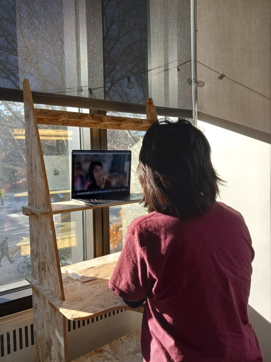
In Use
The desk is sometimes used by students who work in the DUSP lounge. It occupies a corner that looks onto Mass Ave and is quite a nice spot for working. The use cases for its upper shelves are demonstrated below.