09
INPUT DEVICES
This week we had to design a PCB with an input device and read it.
| Tools: | Eagle, SRM-20, Soldering Iron, Arduino IDE |
| Files: | Timer Traces, Timer Outline |
| Date: | 11.09.2022 |
Idea
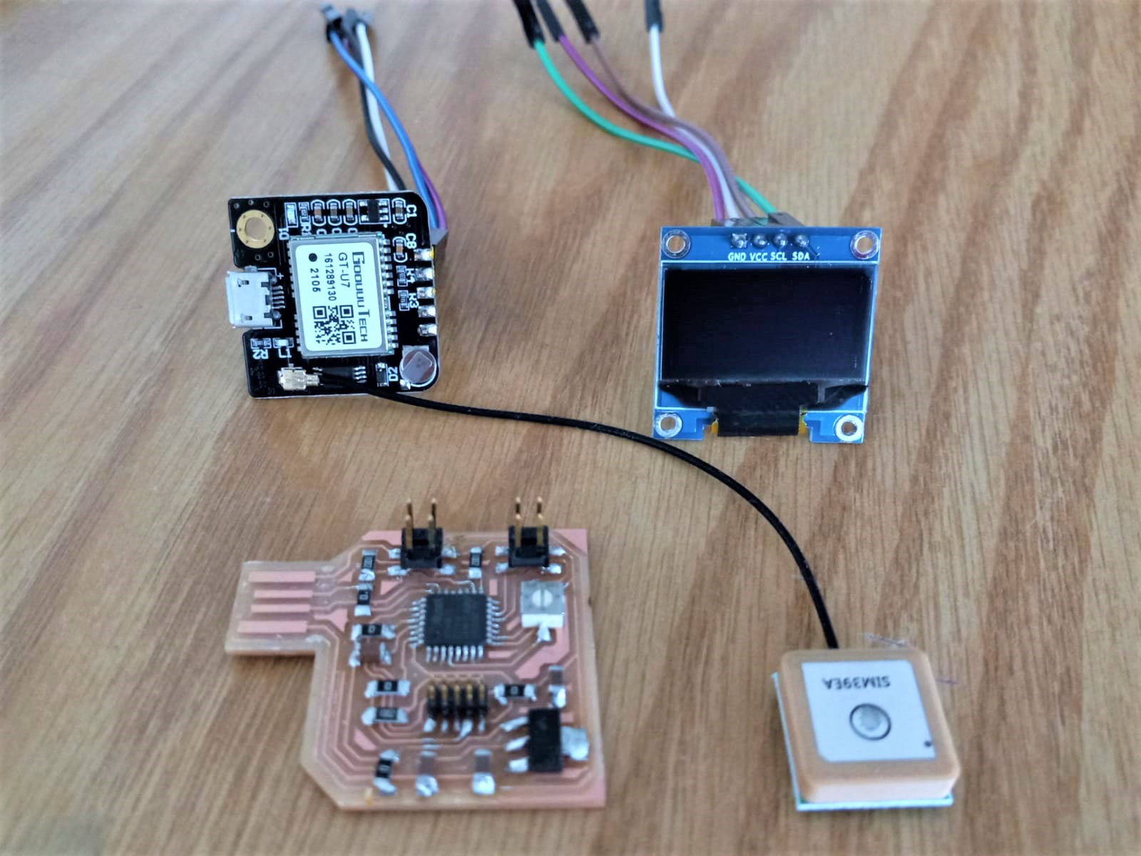
With the intention of moving ahead with my final project, I decided to use this week and the upcoming one to build a timer as a part of a device that would eventually measure my procrastination. I used this fabacademy project for direction. I decided my board would have an RTC module to receive time, a potentiometer to set the timer, and an OLED to display the time. The RTC and the potentiometer would thus be the input devices. However, I spent so much time getting the board to come alive that I only managed to program the potentiometer.
Schematic Design
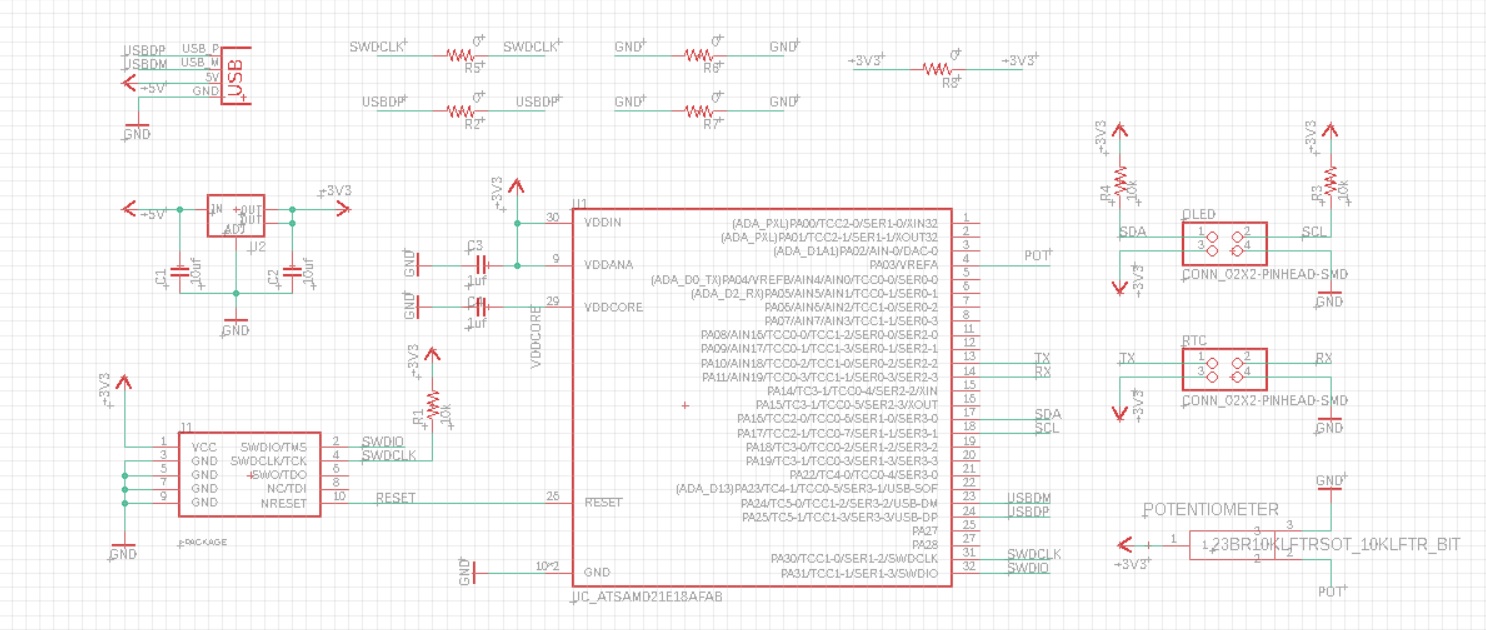
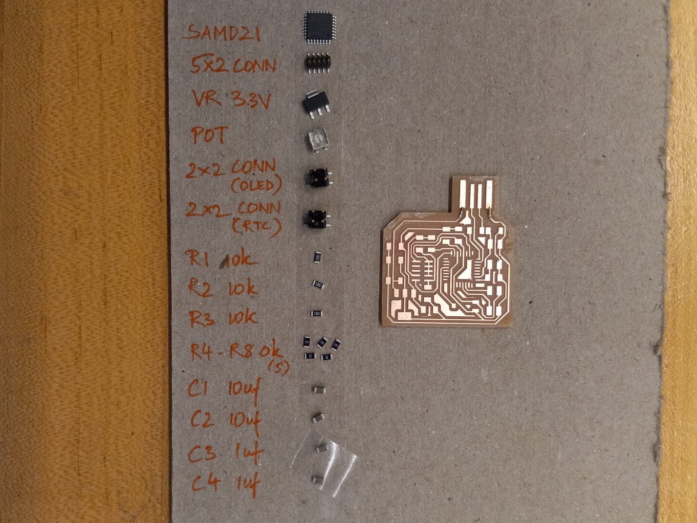
Since I could not find an RTC module in the archshop, I ended up choosing the GPS module based on Neil's example, for measuring time. I also wanted to challenge myself to use a different microcontroller, and decided on the SAMD21E17A which has a lot of memory (128kb) and can be powered through a USB. In the schematic you'll see, 2 2x2 headers for the GPS and the OLED respectively--this way the parts don't need to be soldered onto the board, thus eliminating some potenitally frustrating routing.
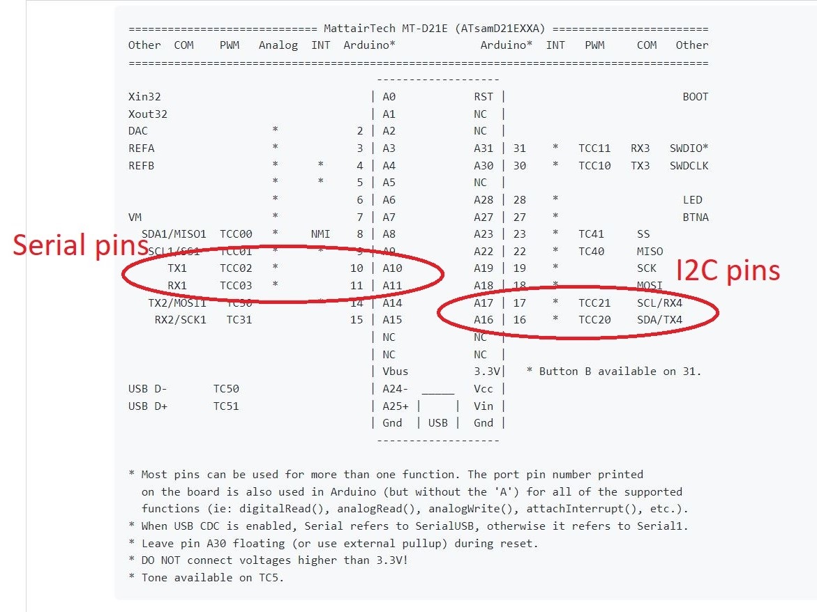
The GPS module would connect to Serial pins (TX and RX), while the OLED would connect to I2C pins (SDA and SCL). I referred to the pinout map on the mtm microcontroller guide to find the right pins.
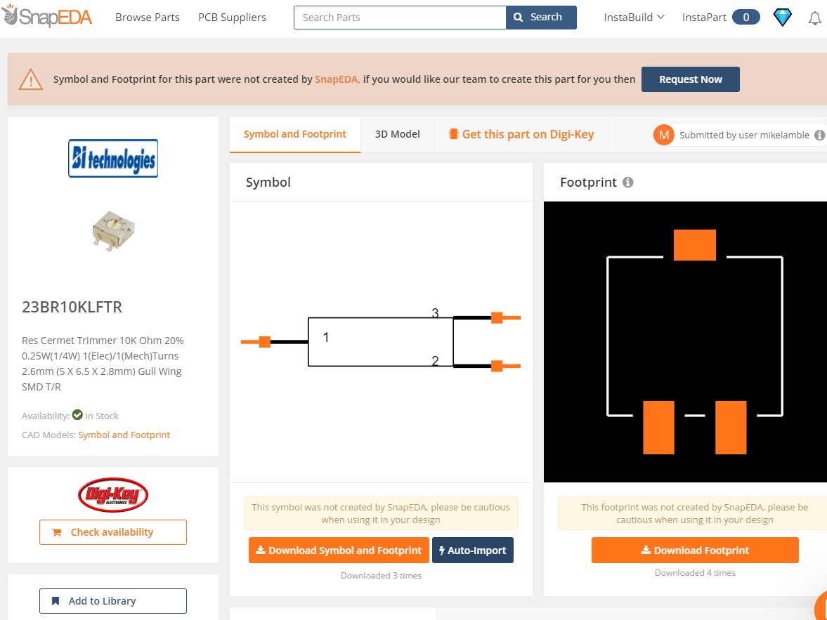
The footprint for the potentiometer was missing from the fab library, which prompted me to dive into the world of footprints on SnapEDA. I downloaded and imported the footrprint that corresponded to the potentiometer in archshop's inventory.
Between Jake's tutorial and Anthony's help, I finished the schematic:
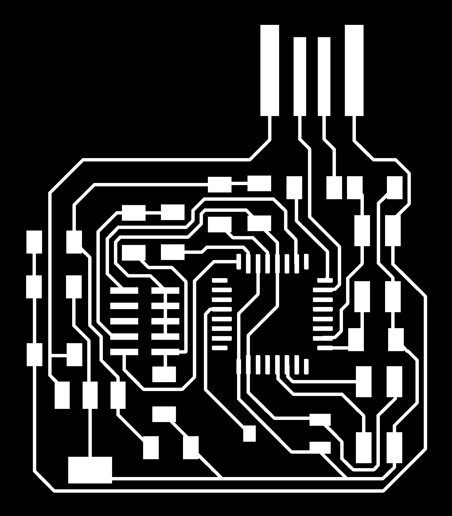
Board Design
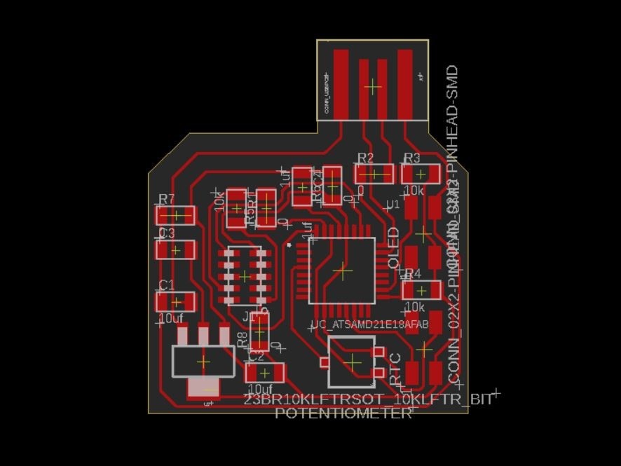
The routing for this one took me very long! Despite my best efforts, I ended up using 5 0ohm resistors. For some reason, although I used the same design rules, the traces for these boards came out too thin everytime (4 times!) I milled them. I used different 1/64" endmills too to see it was an issue with worn ends. I imagine it's probably because I was using a very fine grid while routing on Eagle and kept trying to push traces closer together to reduce the size of the board.
Mill, Solder, Repeat
When choosing the microcontroller, I did not anticipate that it would be infinitely harder to solder 32 very small pins with the soldering iron. Would definitely have settled for a different one, if I had known what was to pass.
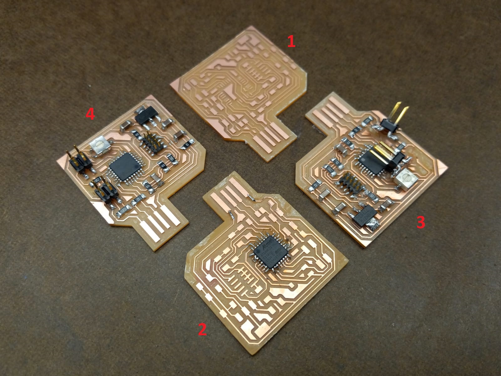
My first attempt at making the board ended with the milling process. Some of the pads for the microcontroller pins which were not connected to anything got lost in the milling machine. I thought it was probably a faulty end millm, so I tried milling again.
My second attempt at milling was not that much better (traces were still too thin), but no pads were missing atleast. It ended after I soldered some microcontroller pins together and was unsuccessful in desoldering.
My third attempt took painfully long. Traces still too thin. I spent a lot of time soldering (and desoldering) the SAMD21 pins using the iron. I finished though. Sadly, this time some traces got ripped out when the 2x2 header got stuck to a thread in my bag. This board started to seem doomed.
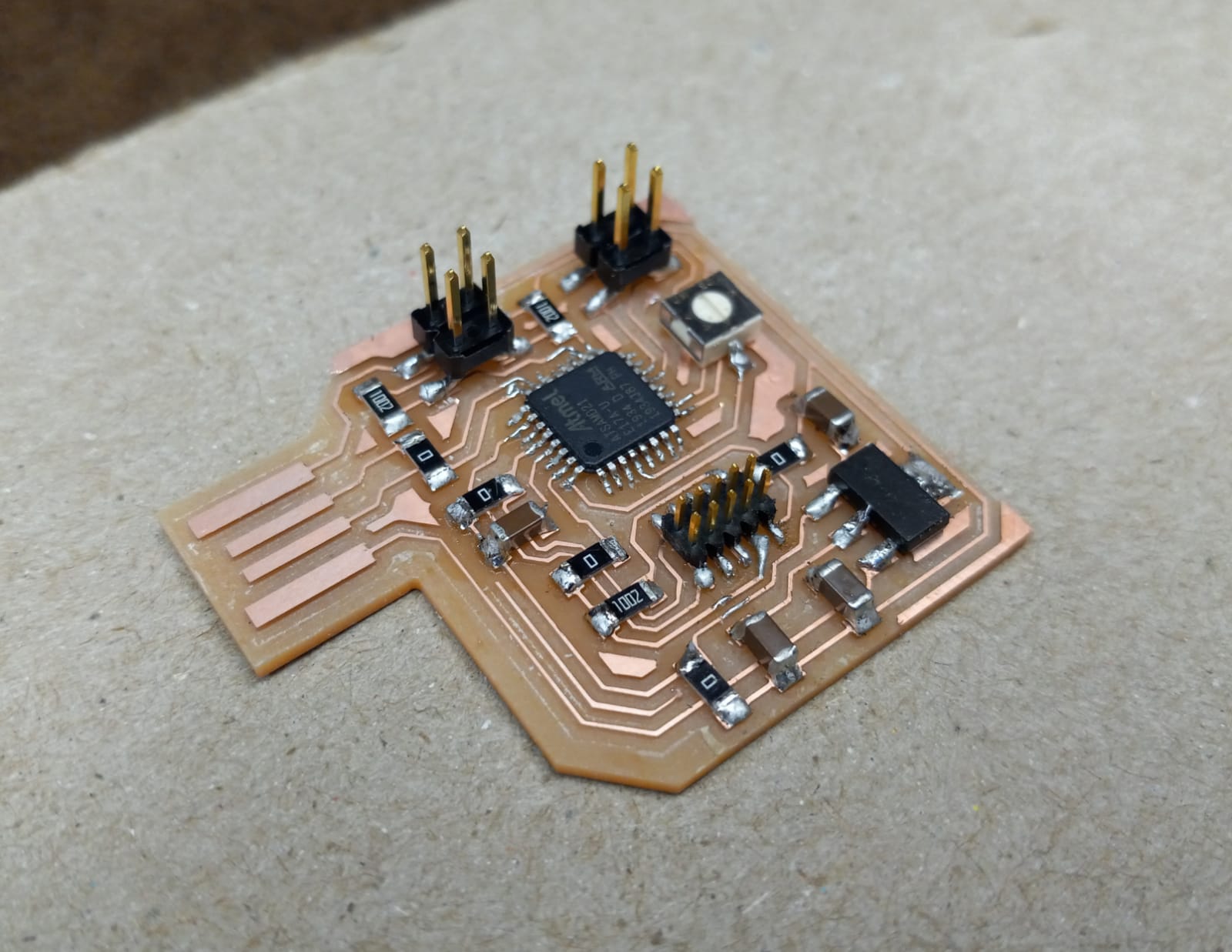
My fourth attempt was saved by Chi-Li, who showed me his technique of soldering with paste: inject a very small quantity near the pin and use the iron to heat and push the paste towards the pin. This was so much more convenient and surprisingly fast.
Input Device 1: Potentiometer
Bootloading the board took significant effort as well. For some reason the edbg method was not working on the board. Anthony helped bootload through Arduino IDE directly using "Burn Bootloader", which worked perfectly. I went on to program the potentiometer using code that I found on the aforementioned website. I modified the pin number pointing to my potentiometer on the SAMD21 and pushed the code successfully. It maps the scale of the potentiometer, converts its reading to a percentage and prints both the actual reading as well as the percentage in the Serial Monitor.
    const int analogPin = 3;
    int value;      //variable that stores the raw analog reading
    int position;   //potentiometer position in percentage

    void setup() {
      Serial.begin(9600);
    }

    void loop() {
      value = analogRead(analogPin);           //perform raw analog reading
      position = map(value, 0, 1024, 0, 100);  //convert to percentage
      Serial.print("RAW VALUE:");
      Serial.println(value);
      Serial.print("PERCENTAGE:");
      Serial.println(position);
      delay(1000);
    }
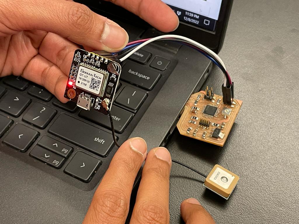
Input Device 2: GPS module
I tried finding examples (and libraries) for SAMD21 to program the GPS module, but could not find anything that worked. The module lit up when connected to the board, so it was clear that it was receiving power. When I went outdoors it also startes to blink, which I assume is what happens when it is receiving data. It was late so I figured one input device would suffice for the week's assignment and postponed debugging the GPS module to a later time.
I learnt later that I can make a timer by just using the microcontroller and the delay() command (see final project), so I never really went back to debugging this module.