How To Make (Almost) Anything Neil Gershenfeld
MCKENZIE ROSS HUMANN
MIT Department of Urban Studies and Planning
VINYL + LASER CUTTING
09.21.22
group assignment: characterize your laser cutter’s focus, power, speed, rate, kerf, joint clearance, and types
individual assignment: cut something on the vinyl cutter design, laser cut, and document a parametric construction kit, accounting for the laser cutter kerf, which can be assembled in multiple ways, and for extra credit include elements that aren't flat
Vinyl Cutting
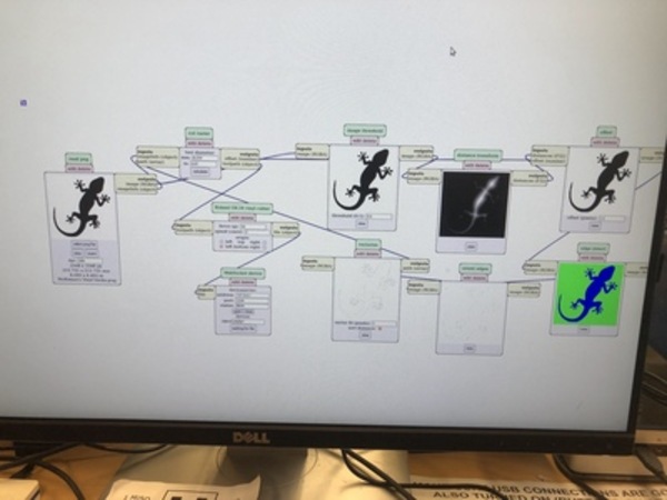
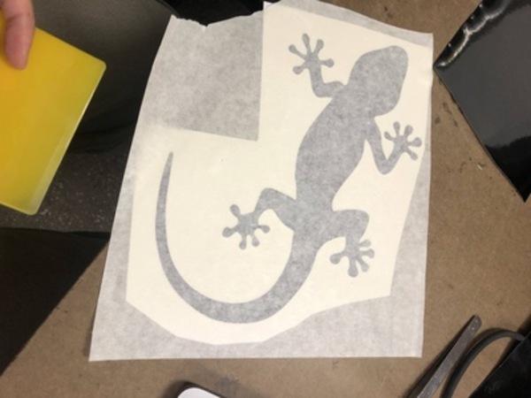
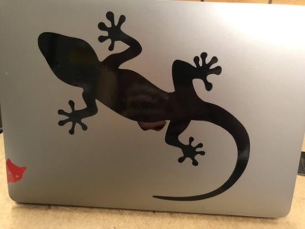
Along with most everyone else, I cut a new laptop sticker. Lakshmi and I practiced with cutting a little cat sticker, where we learned our first lesson about paying attention to the size of the png file. In my second attempt, I perhaps overcorrected and printed an 8in by 8in gecko. You can see in the photos on the left how I used mods, cut the sticker, peeled off the negative, attached the adhesive and applied to my laptop. For any future stickers, I'll try to remember about the apple logo...
Laser Cutting
First for the group assignment, Lakshmi and I measured the thickness of the cardboard using the digital calipers as 3.81mm. Using the 60Watt Universal Laser Cutter, we cut some test pieces with joints 3.81mm, 3.84mm, 3.87mm of which the largest joint fit the best. Before cutting, we adjusted the height of the laser so that it was 2in from the top of the cardboard. Since this was a test, we used a scrap piece of cardboard that was not very flat; we noticed that the areas with the greatest warps did not cut as well. We used 30% speed for these tests, 25% power, and 500ppi. For other pieces, we tested decreasing (10%) and increasing the power (27%). The 10% power did not cut all the way through, but rather scored the material. Based on these test cuts, we measured the kerf to be 0.25mm.
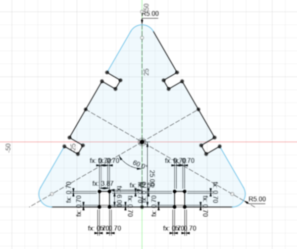
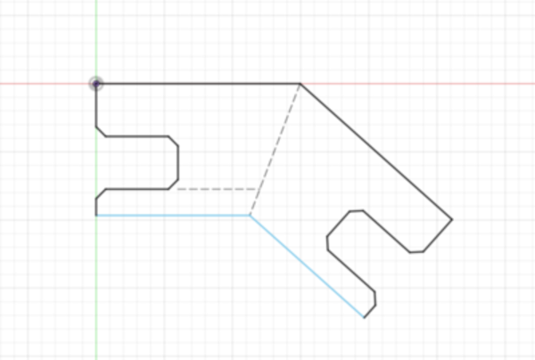
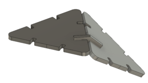
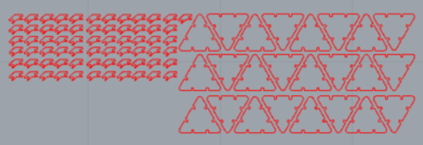
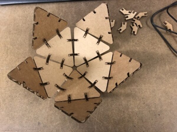
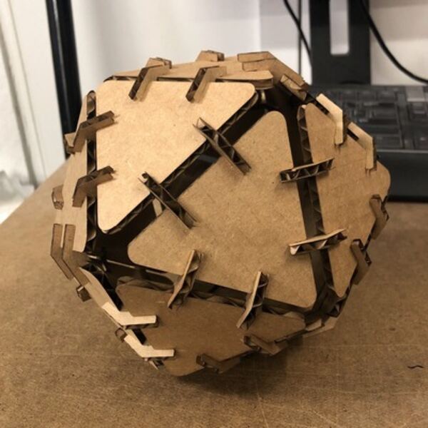
For my project and as a new CAD user, I wanted to use this week as a low stakes opportunity to practice CAD and learn how to use the laser cutter. Taking inspiration from a past student, I followed their detailed instructions for how to make a regular icosahedron - a 20-sided polyhedron made with equilateral triangles. I made the 2D designs in Fusion 360 for both the triangle and the angled connector, and then extruded them to see how they would fit together in 3D. Then I exported the 2D designs, imported to Rhino and did a test cut using 30% speed, 25% power, and 500ppi. The initial test pieces were fine but were a little difficult to pop out of the remaining board so I increased the power to 27% to cut the remaining pieces. This definitely helped with the pieces closer to the edge of the board, but the pieces toward the center ended up still being a bit tricky to remove. I was still able to use all the pieces from my first cut and then assembled the icosahedron with only a little bit of struggle.