Final Project
History
Cockpit is where the pilots work. It is said to be the most attracting office in the world. My dream as a child, is to become a pilot in the future. Unfortunately, because of my eye problem, I can never be a business pilot. As a result, I spent long time practicing aircraft piloting and build many stuffs related to the airplanes.
Since piloting an airplane is so complex, flight simulators are built for training purpose. I am very fortunate to have work experience in flight simulator companies to develop avionic software and get chance to play our own products (fixed-based training devices) and play very advanced products (full-motion training devices.
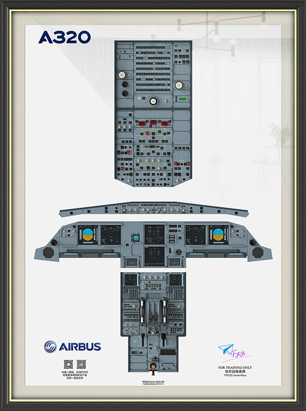
While I was working in the company, I still want to do something to get closer to those pilots. Thus, I started to build 3d models of the cockpit and draw very realistic cockpit posters. Until now, my drawings have served more than 3000 pilots around the world. This makes me feel very proud.
As a flight enthusiast, like many other enthusiasts, I collect many airplane models. All of them are metal, with a very large scale (1:200). I will make sure they are dustless by sweeping them frequently. While I was cleaning my collections in one day, I suddenly noticed something. If an airplane models can be built, why there isn't anyone building the cockpit models? Since then, I have an idea of making a cockpit model.
Concept
With the idea in mind, I plan to build a cockpit model having the following features:
- Scale = 1:5
- Backlit panel
- Easy assembly
- Realistic
Design
In general, I wish to achieve the following functions:
- The entire cockpit should have backlit panels for overhead, glare shield, MIP and pedestal
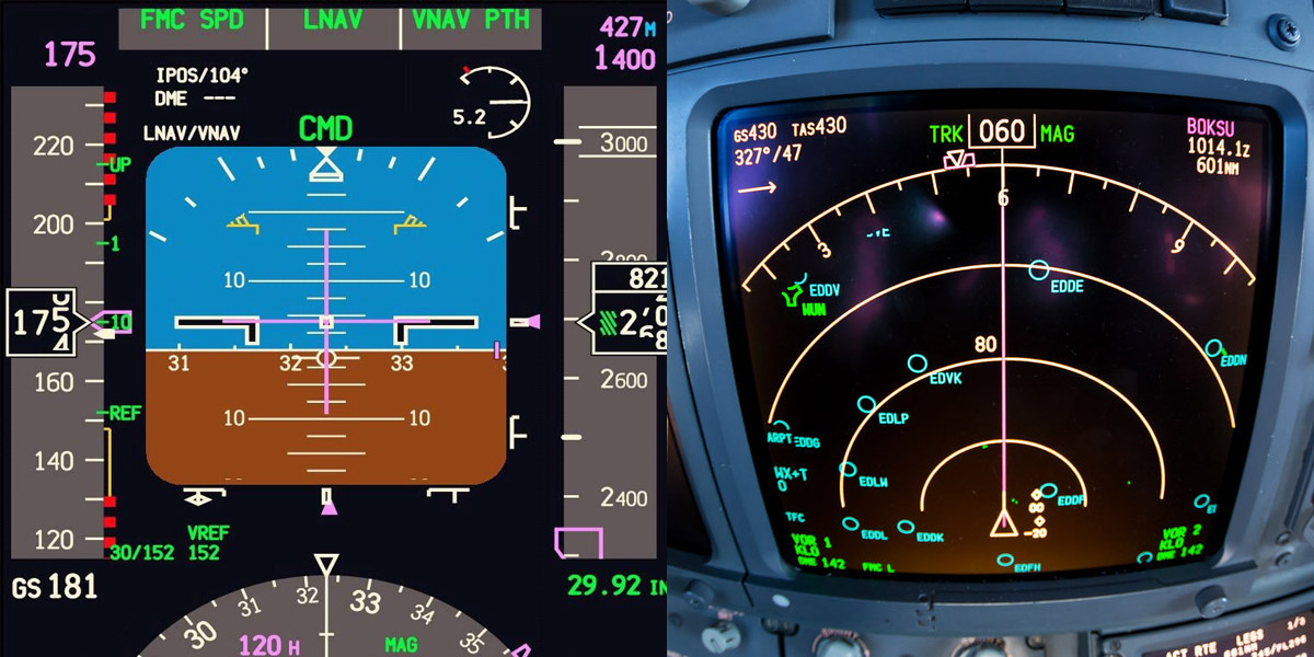
- The cockpit should have at least two screens with real display
With these ideas in mind, I split my design work into three main parts:
- structural design: design the wood frame of the cockpit.
- electrical design: design the backlit circuit and screen display circuit
- software design: design the code to control the tft screens
Structural design
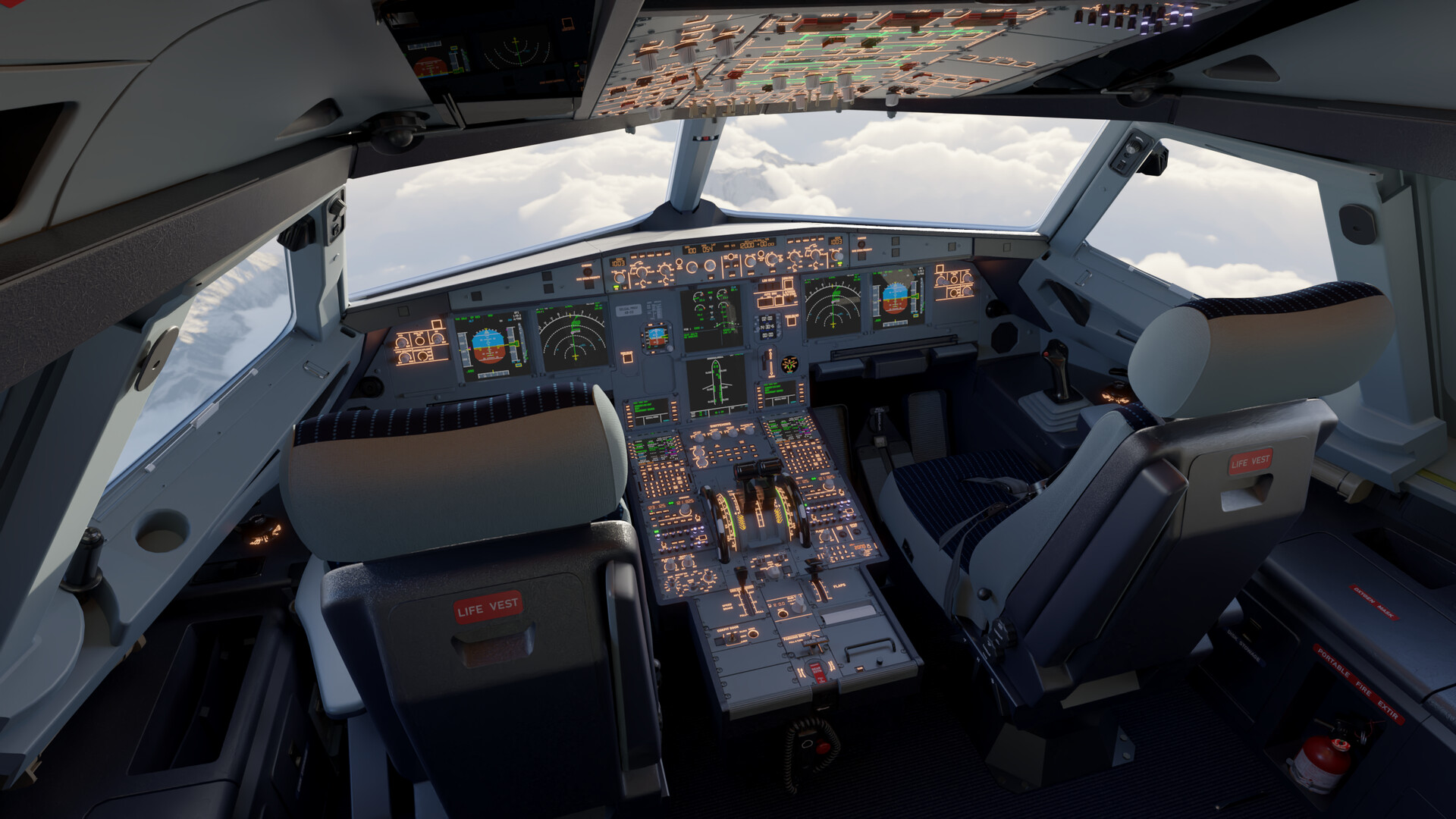
Following the extracted model from MSFS2020 game, I model the cockpit using Solidworks software. You can see my design below:
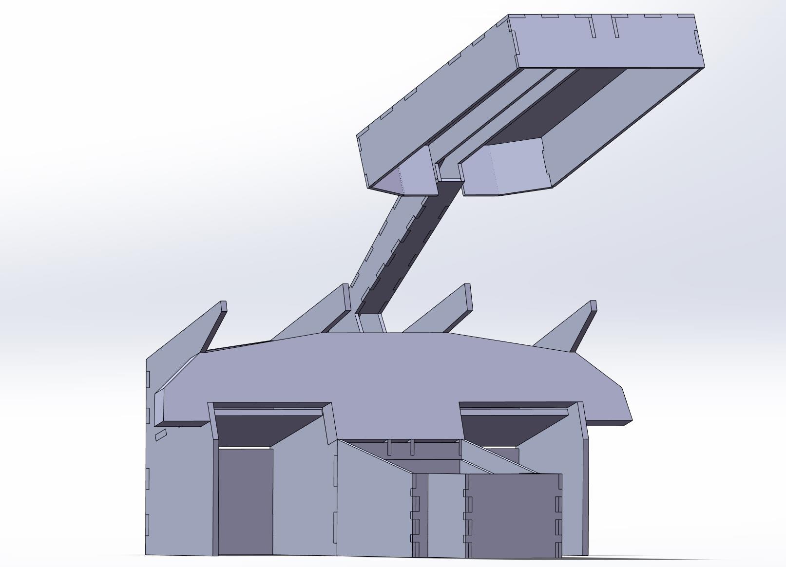
I used the parametric method taught in the class to establish my models. For example, the MIP backbone wood thickness is 3 mm as designed. This can make sure that all my designs follow the same design rule.
Electrical design
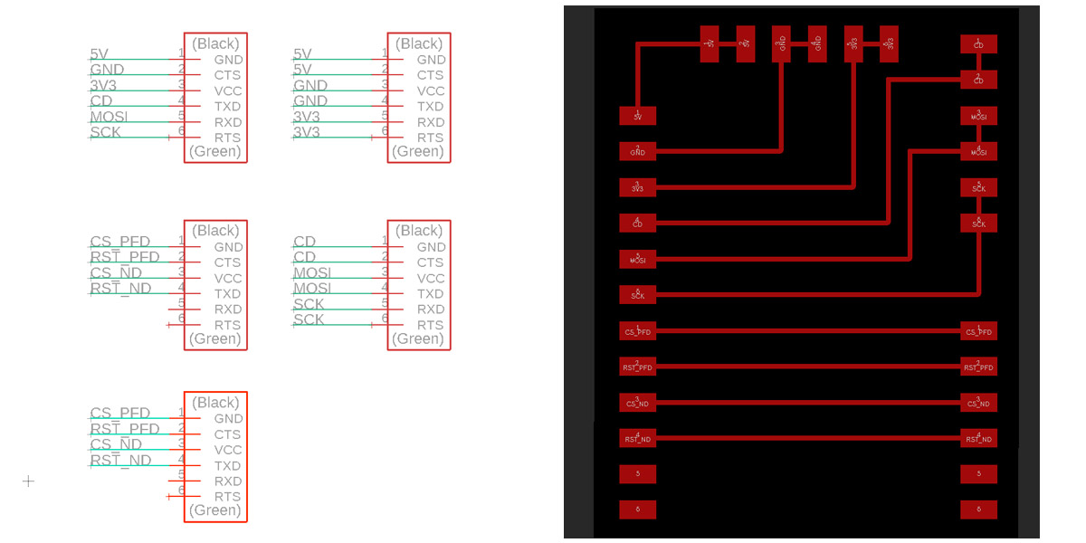
Having tried several hours with TA, I give up the idea of using D11C to control the TFT screens. Instead, I bought a Mega2560 to control multiple screens. The wiring is designed as the following:
- MOSI: 51
- SCK: 52
- CD: A1
- RST_PFD: A3
- CS_PFD: A4
- RST_ND: A6
- CS_ND: A7
During the electrical design period, I found the following links to be quite helpful:
- QVGA 2.2 inch SPI: link. This site illustrates all you need to know about the TFT screen.
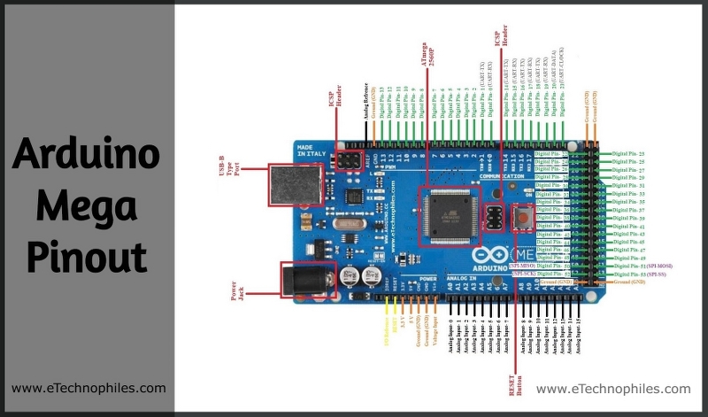
- Mega2560 pinout: link. This site illustrates the function of Mega2560 pins
Software design
After having a robust hardware system, I can start my software design. I first run the sample code from here: link. Then, I plan to develop the screen display for PFD and ND screens for pilots. Initially, I wish to achieve a dynamic screen. However, due to the limitation (listed below) of the TFT screen, I finally made a static one.
- Slow screen clearing: whenever you want to clear the screen and redraw the components, you need to wait for a long time.
- It is impossible to scroll a rectangle area up or down. Instead, you can only scroll the entire row up or down.
Fabrication
There are three aspects of fabrication involved in this project:
- Laser cutting: cut the wood frame of the cockpit
- Laser engraving: engrave the text and lines on the surface of panels
- PCB board fabrication: fabricate the converter board between two TFT screen and the Arduino board
- 3D printing: print the pilot chairs
Laser cutting
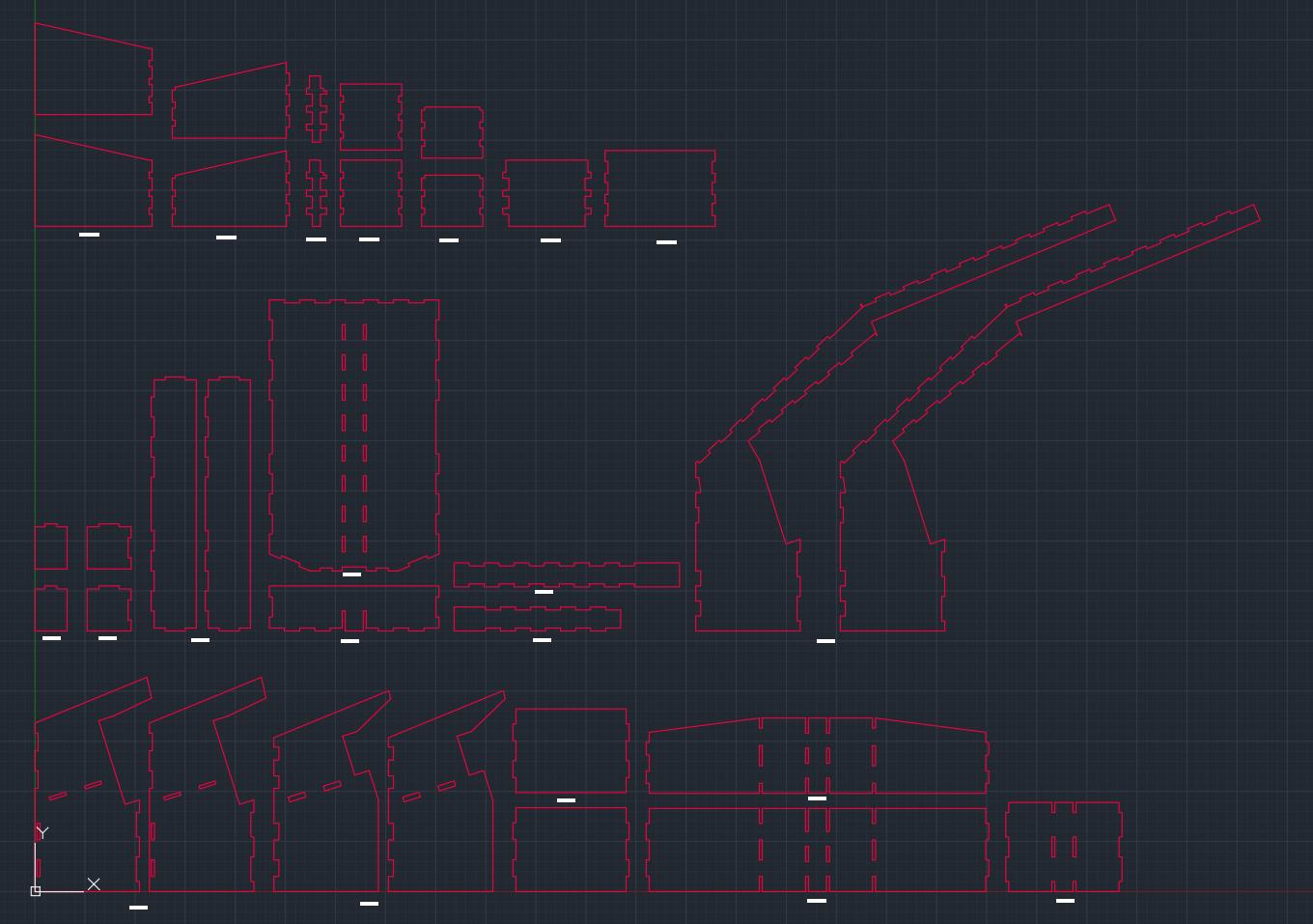
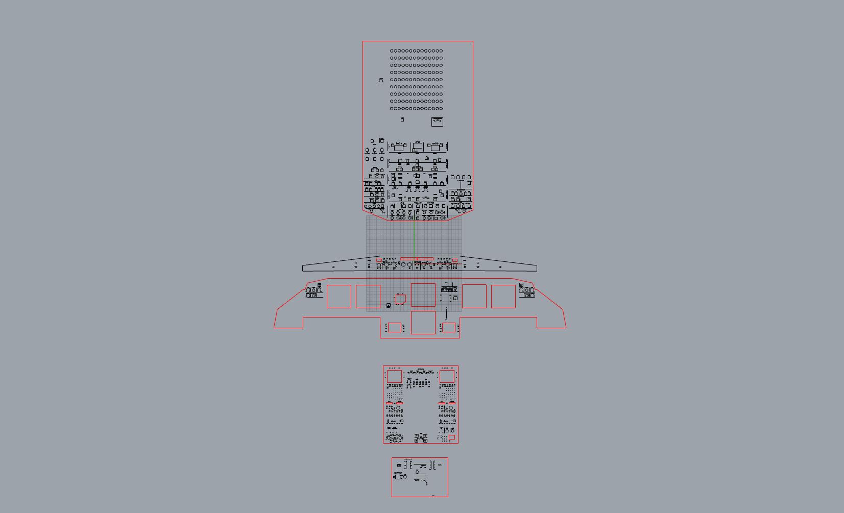
After having the design, I draw a 2D file and get ready for the laser cutting. Considering the convenience, I decide to use all 3 mm wood/board etc.
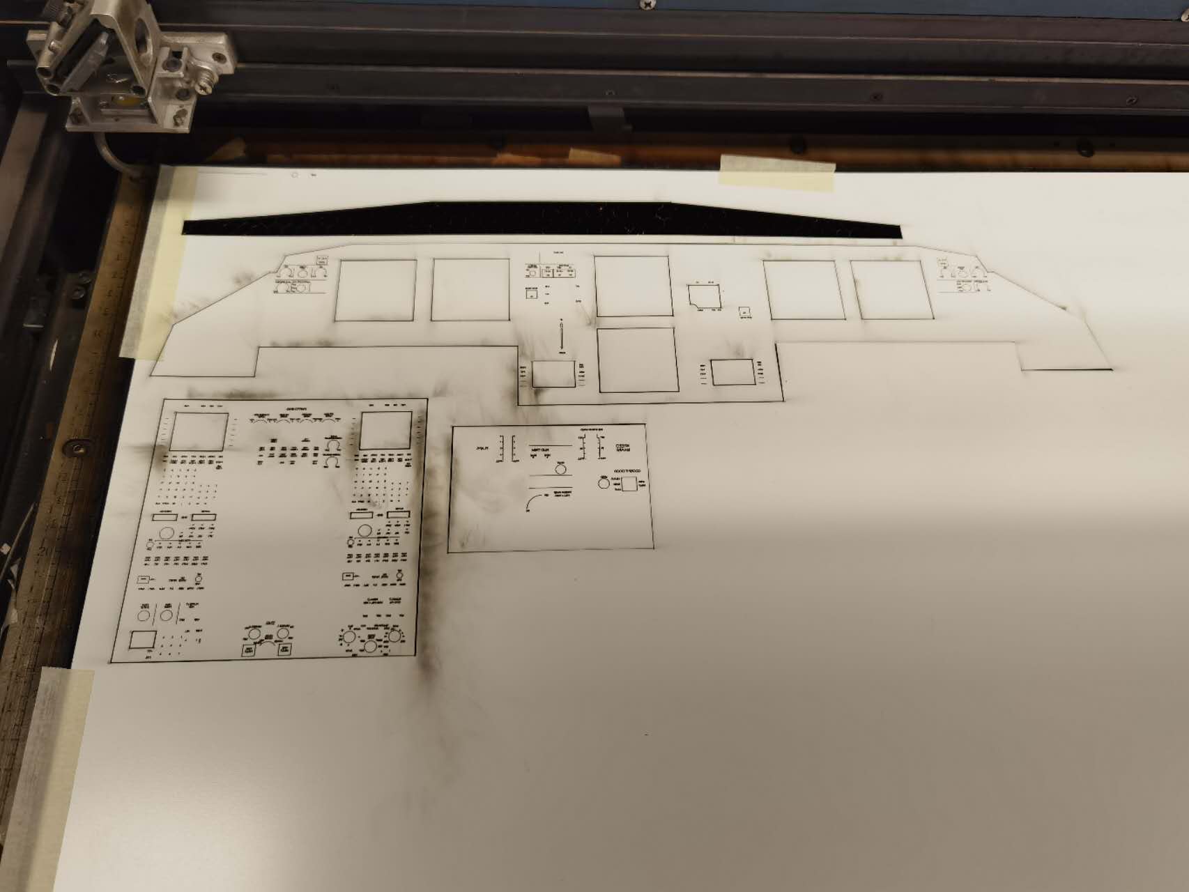
Cutting the board is never easy. During the entire cutting, I have the following problems:
- First, the board is not flat. Even the focus is calibrated, when the laser cutting header moves to another place, it might de-focus because of the curve of the material.
- Second, the machine will sometimes trap in the software loop, with no response to any command. I have to repeatatively restart it.
- Third, as I am using the left material of others, finding a good place to cut is very difficult, especially when I am trying to cut something huge.
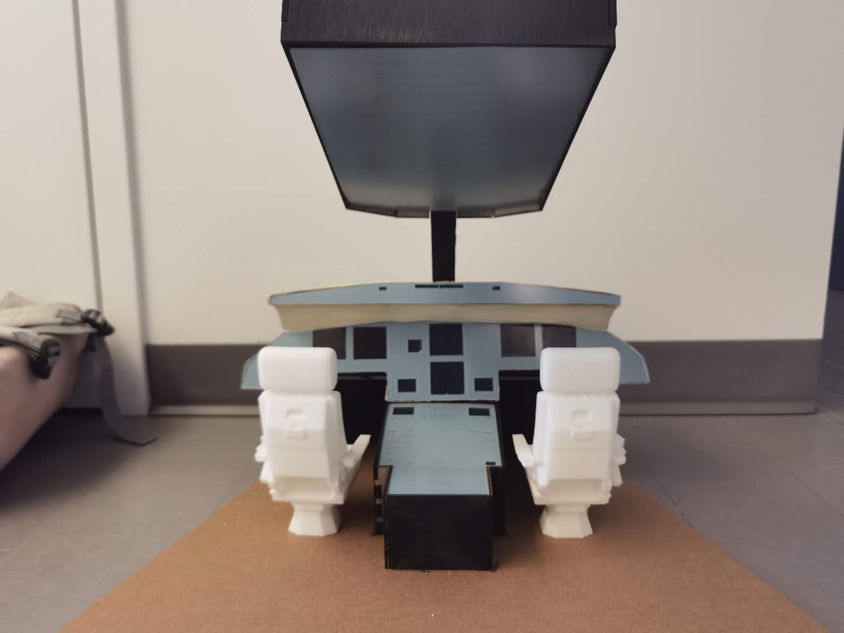
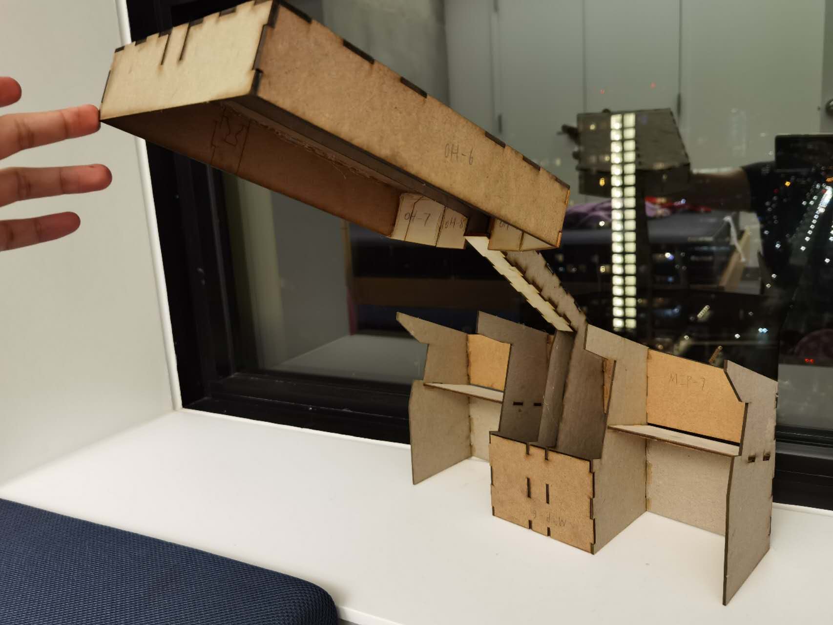
After addressing all those difficulties, you can see the assembly below:
Laser engraving
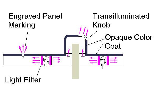
The next part to think about is the backlit panel. According to what I know, the real airplane has the following steps to fabricate a panel (check the link)
- First, get a transparent plastic sheet
- Second, paint the white color to the surface of the material
- Third, paint the gray color to the surface of the material
- Use laser to engrave the first color layer to display the characters
- Check the intensity of glowing and adjust the light intensity
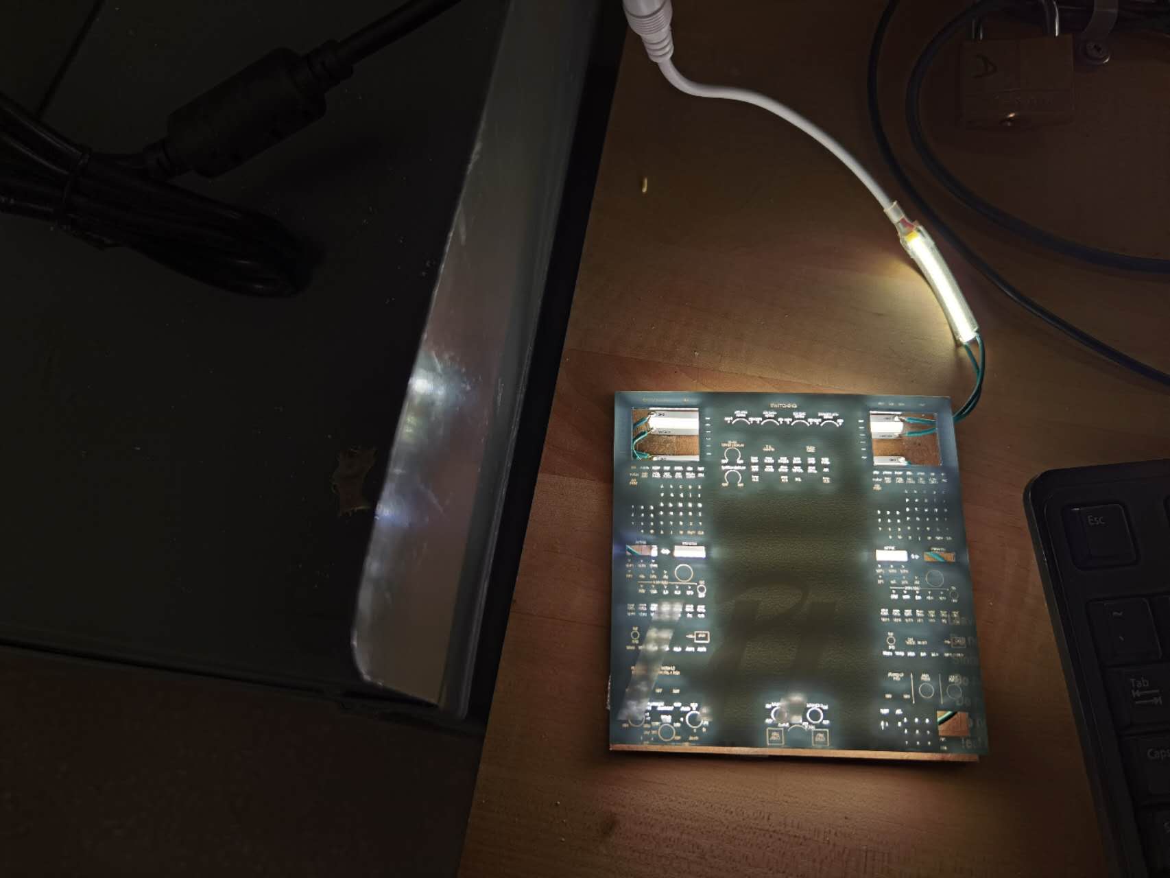
Apparently it is very difficult for me to achieve the similar quality. I need to find a simple solution. After discussing with Jen, we believe a reverse clear engraving sheet should work well for my case. I borrowed a small piece from Jen to do the experiment:
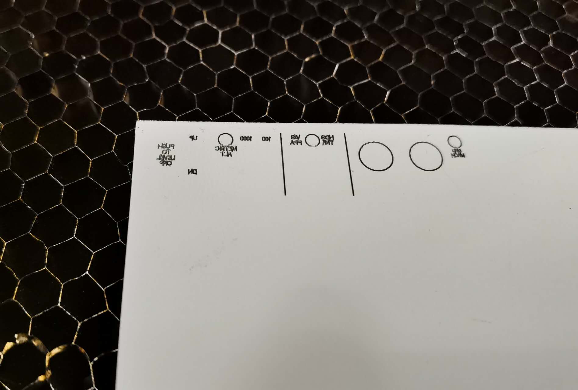
As this is a 1:5 scale cockpit to the real aircraft, the text are super tiny. They are only 0.6 mm height in my scenario. And as you can in the image, the text are also skewed due to the small size. The other thing need to be noticed is the font. In Rhino, the default font has double line, which doesn't fit my case. So I downloaded the single line font from here
Drawing the texts on airplane panels is a time-consuming task...
After having the panels, I started to work on the source of light. Instead of using the LEDs provided by the shop, I decided to use the light strip I used to buy as it is powered by a 24 volts supply which is more powerful.
PCB board fabrication
Following what I learned in the previous weeks, it is relatively straightforward for me to get the board fabricated. I use the male pin connections so that it is easy for me to test and assembly.
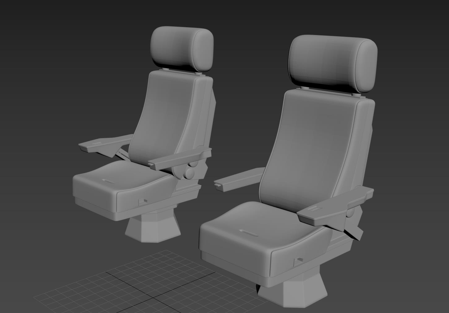
3D printing
The extracted 3D model from the game is originally not suitable for 3D print, since the object is not a closed body. I used 3D max to fix the body and here you can see it:
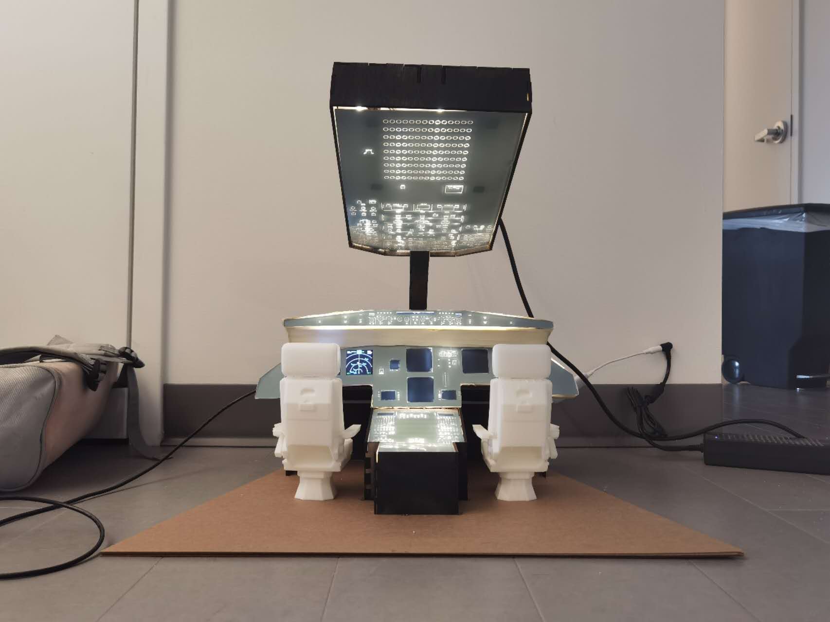
Finished result