

Besides my site, I also created the shared group project page. You can see it here: link
Week 1 computer-controlled cutting
Group Assignment
Individual Assignment
In this week's class, I learned the basics of doing parametric design as well as exporting the file for laser cutter to actually cut the board.
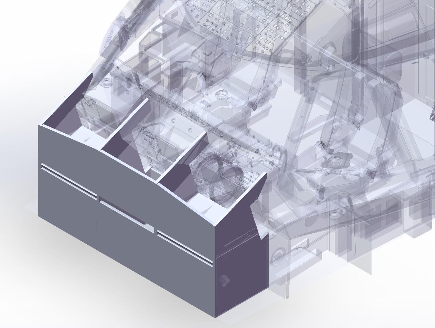
As described in the Final Project section, I would like to build a mini-cockpit. I would like to prove my initial design in this assignment.
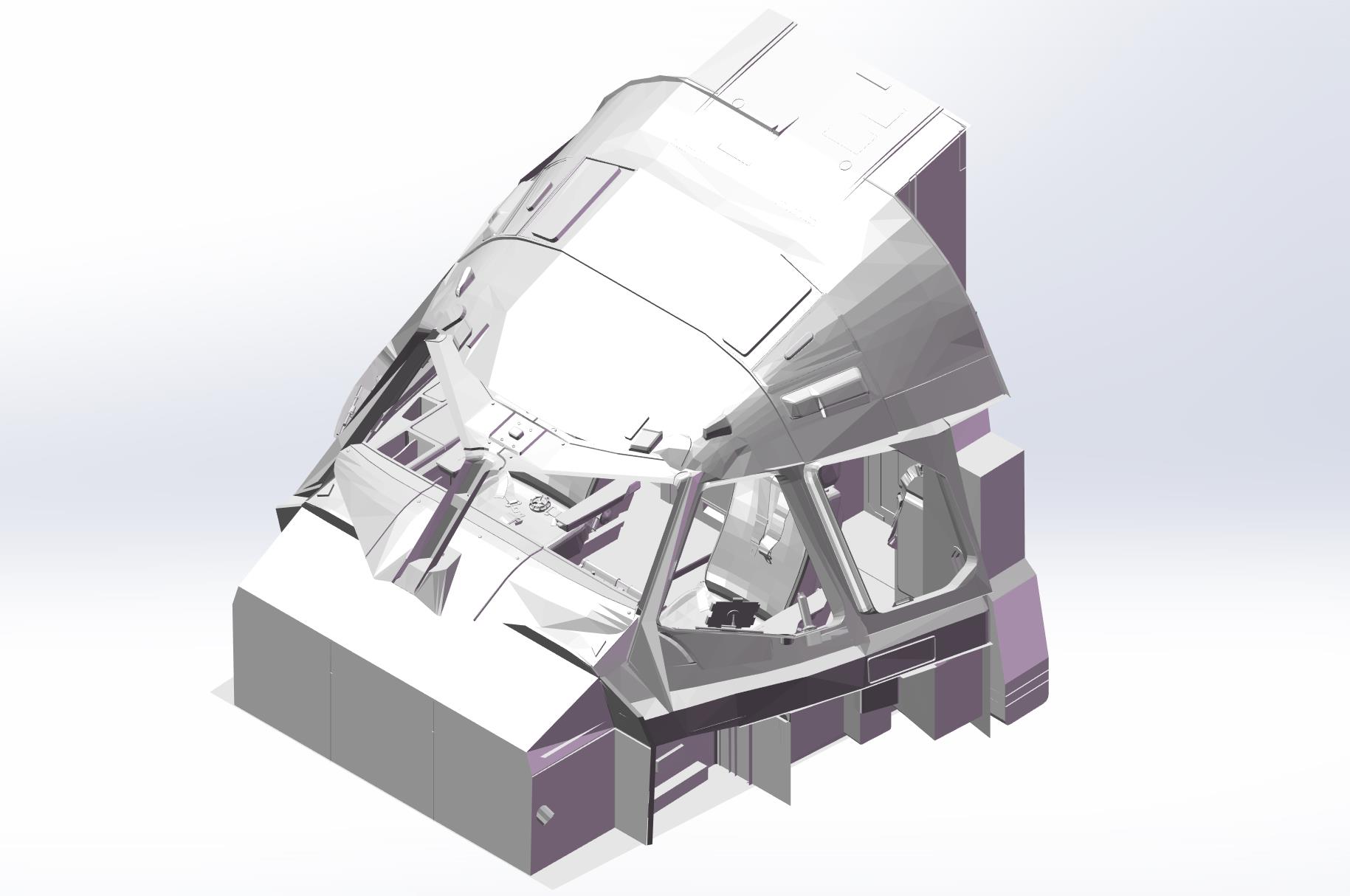
- First, I import the model from a game which has the life scale cockpit.
- Second, I use solidworks to model the basic structure of the main instrument panel.
- Third, I export the 3d model to DXF drawings for the fabrication.
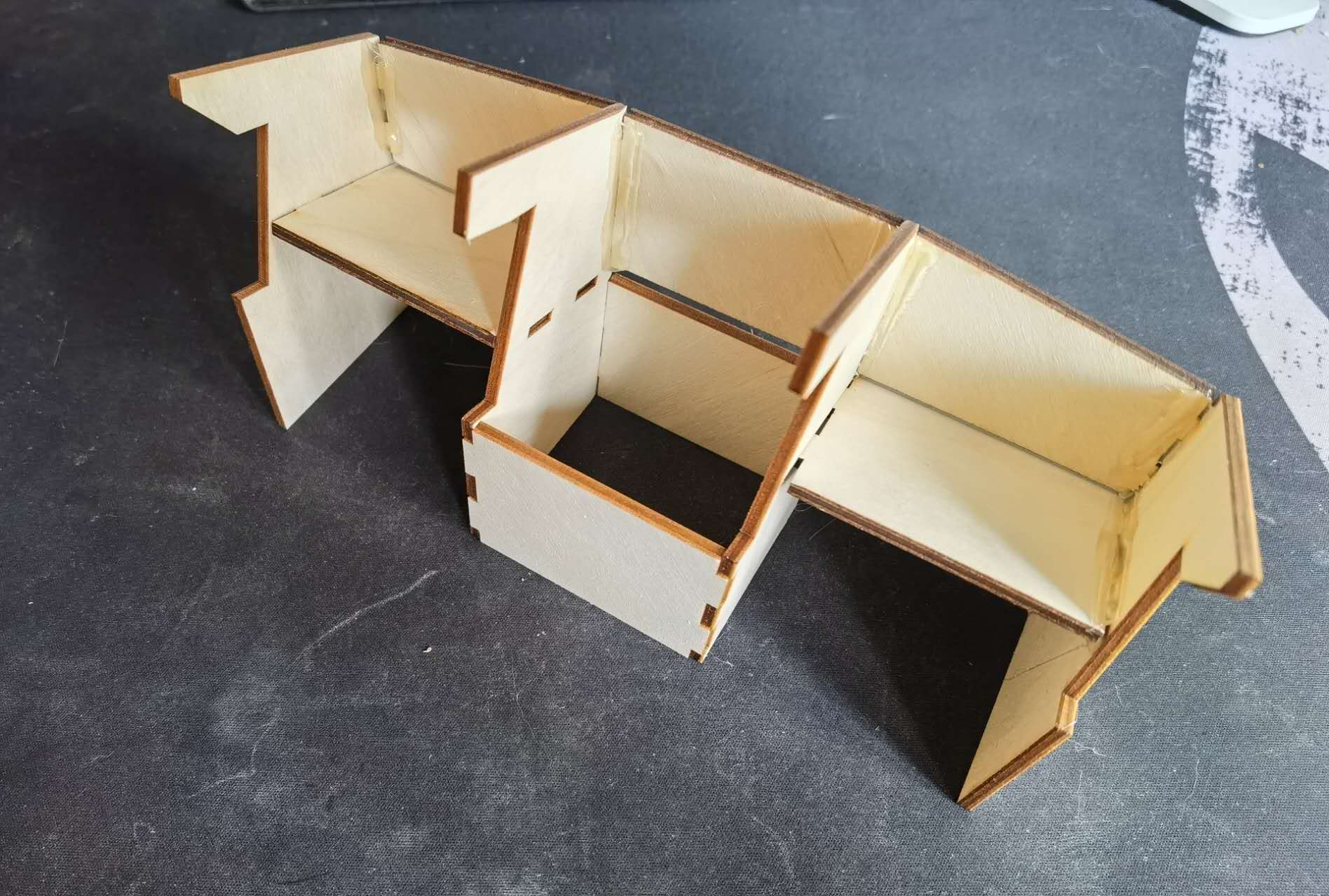
My initial design is to use a 5mm plywood. However, due to the constraint of the material in the lab, I cut a 1:10 model to prove the concept. For this 1/8 inch plywood, I also tried different cutting settings (such as 40% speed and 50% power). Finally, I found that 30% speed and 70% power works the best (1 iteration to cut through the board). After the cutting, I glue them together and this is the result:
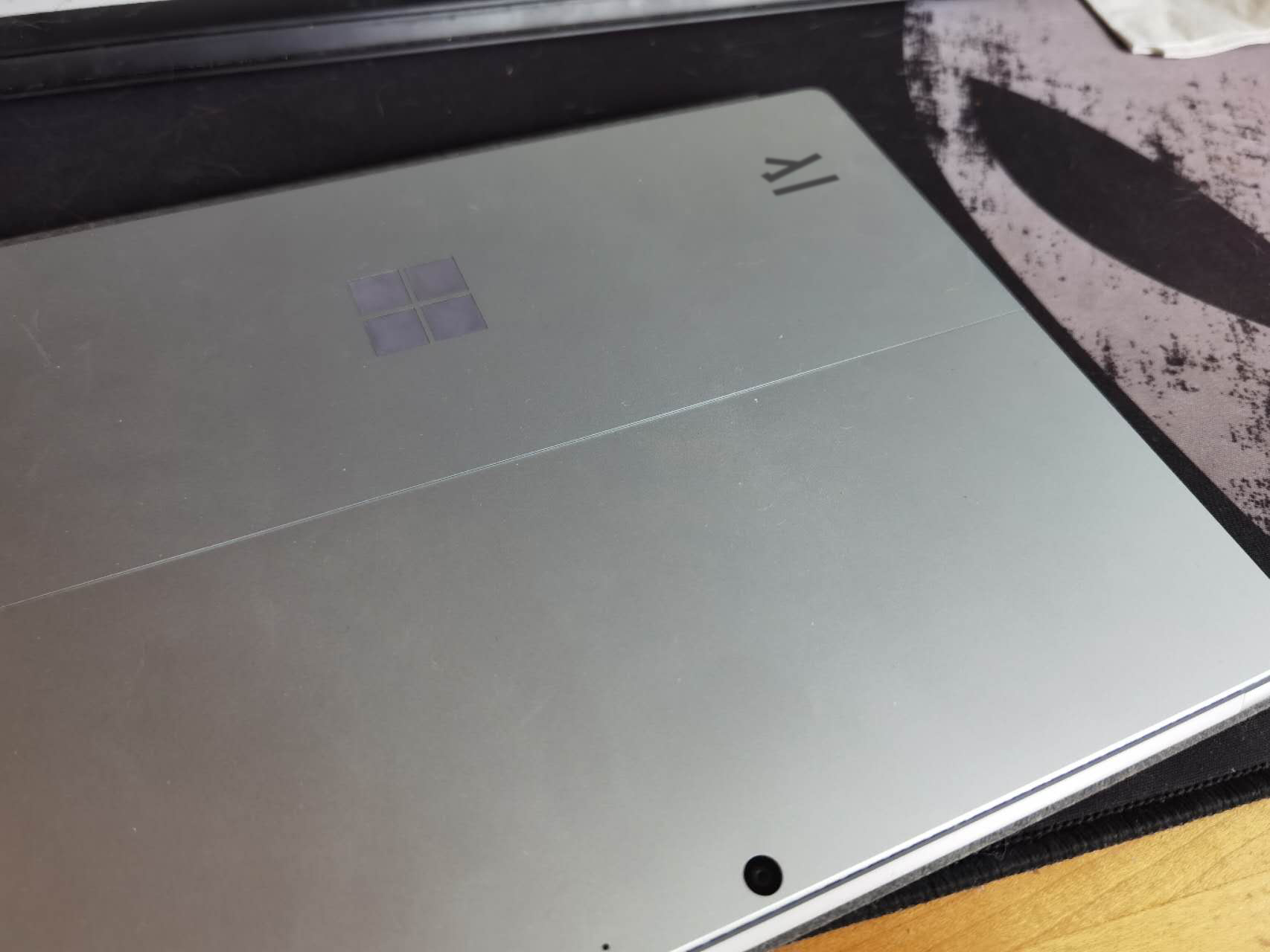
As for the Vinyl Cutting, I followed the suggestion of Prof. Girshenfeld to develop a laptop stickers. First, I go to this website to find a vectorized image I hope to cut.

Then, I just cut it and put that on my laptop
Week 2 electronics productions
Group Assignment
Individual Assignment
For this week I learned how to produce a demo circuit board within 3 steps:
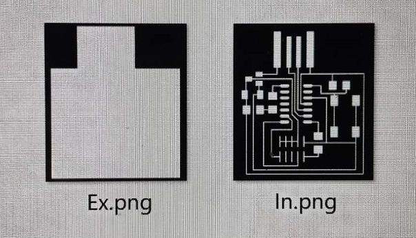
- Design the circuit and generate png based design file (for this time, the board design is provided by the teaching team)
- Manufacture the board.
- Solder the board.
- Program the board.
Before fabricating the board, I joined the group to characterize the design rules. We went through all steps of using the machine and learned the safety cautions. First, always have a good habit of putting tools in order. Second, do not move the board between milling the traces and boundary. Third, remember to keep the work table clean. The entire group keep the rule in mind and build the board:
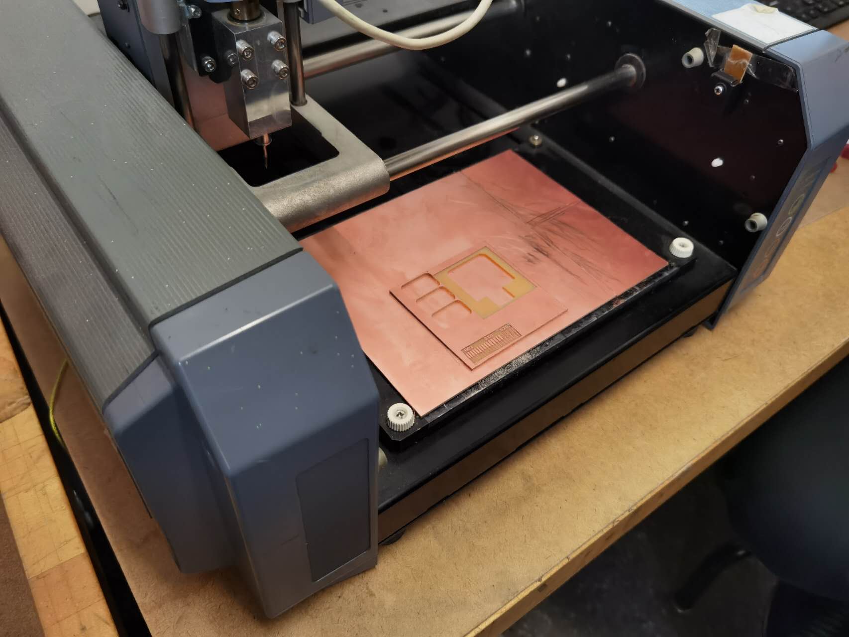
Having the ideas in mind, I started the fabrication of my own board. First, I select the png file for traces. Then I set the application mode to be traces so the machine won't cut the board through. After that, I load the outline png and set the mode to be outlines so the machine will cut the entire board. Everything went well when I cut my board
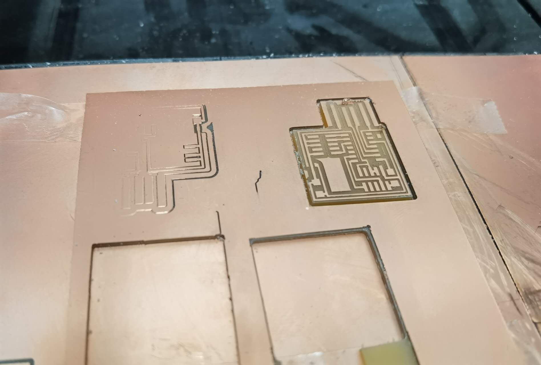
After having the board, I started soldering the circuit. One thing I feel quite frustrated is to find the exact component that we need to solder. For capacitors and resistors they are just fine. However, for the connectors and ICs they are difficult to locate them. It would be great to prepare a BOM sheet next time. Nevertheless, I succeeded in circuit soldering.
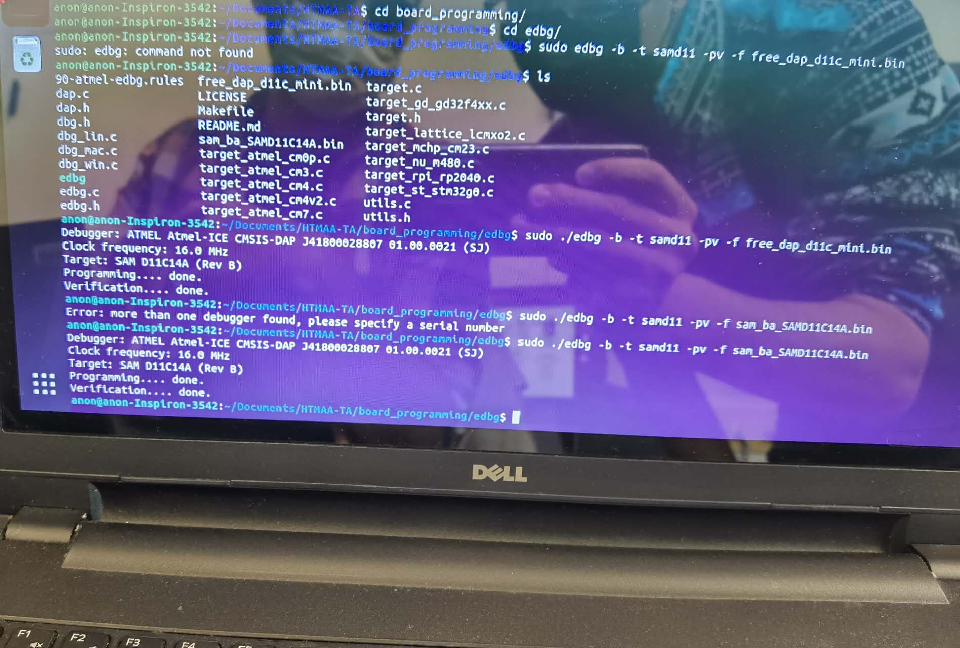
The final step is to work with a TA to test the board. I joined a session on Monday afternoon and got passed surprisingly with just one trial. I now have a bootloader!!!
Week 3 scanning and printing
Group Assignment
Individual Assignment
For this week I learned how to process the STL file for printing purpose after exporting from SolidWorks. Then I also tried the 3D scanning
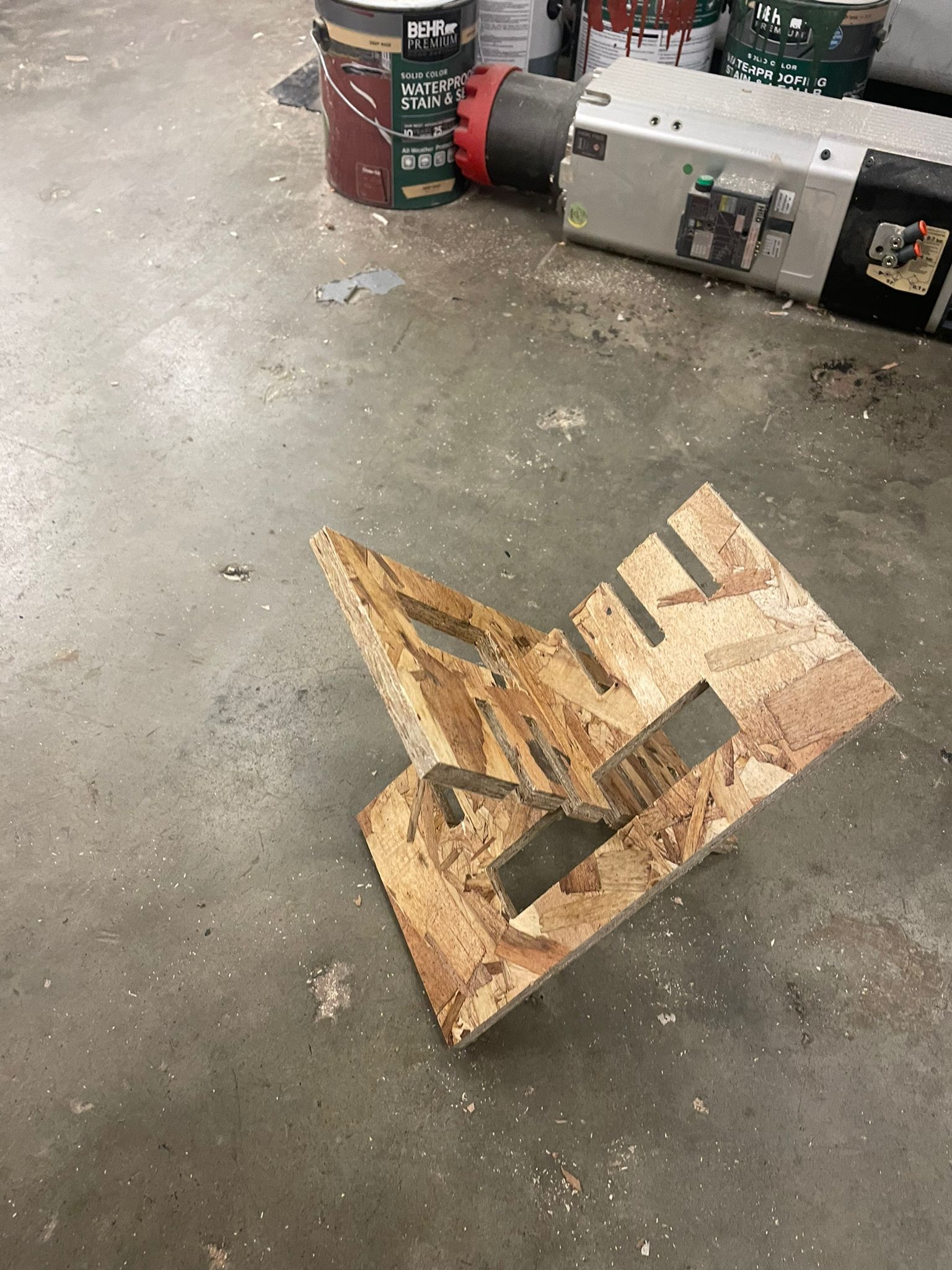
We are asked to print a very small thing, otherwise the printing time would be very long. However, I still want the printed stuff can be unique and meaningful. That makes me think about my name. What if I print my name out? If I simply just print my name in a 2D space, that would be too normal. Can I print my name in 3D? Then I design this:
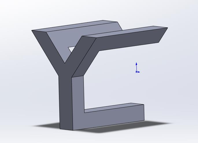
This would be the initials of my name (Yuchen Chai). After that I printed it out and found another usage of that: a hook on the wall. I just want to mention that the angle and position for placing the object on printing face is very important. Otherwise the surface might not be smooth and I need extra supporting structure.
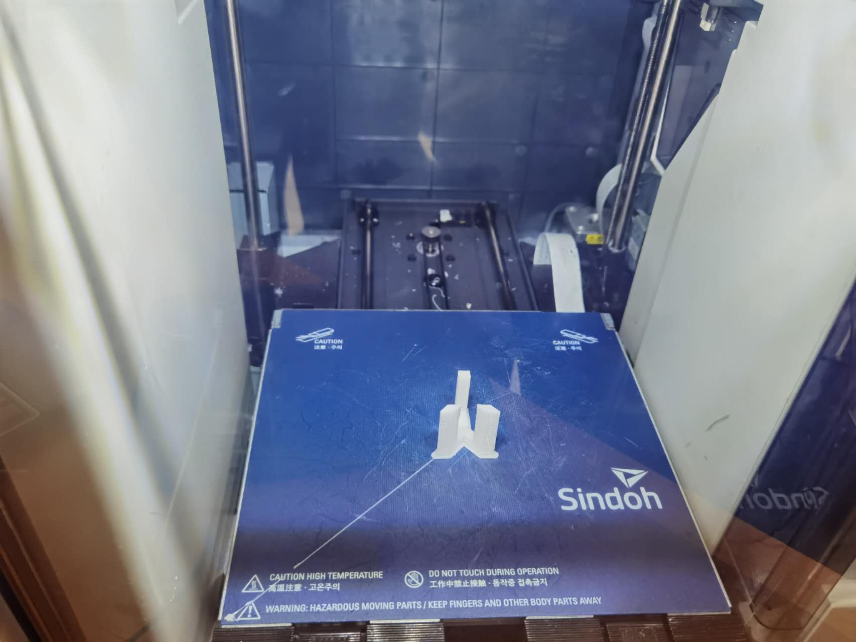
After finishing the printing. I intended to use the scanner to scan it and compare it with my original design. Unfortunately, the lab officer was not at the lab that day so I have to find another time to work on it. I followed the instructions of the scanner. Surprisingly, the scanner didn't work. No matter how I switch the portal to another one on the same desktop or switch to another desktop, nothing works. However, when I told lab officer and tried on their working desktop, it worked. It was the strangest issue I have ever seen.
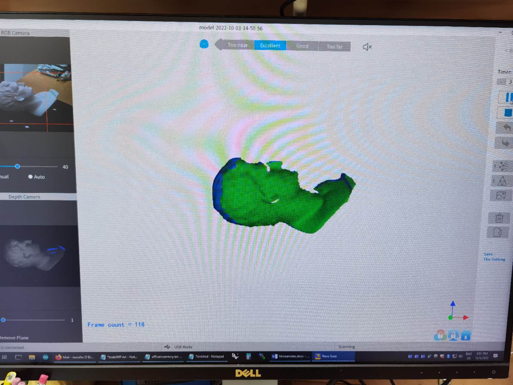
The scanner worked very well for scanning the object. You can see my result on the image above.
Week 4 PCB design
Group Assignment
Individual Assignment
For this week I mainly learned how to design the circuit board from scratch, generate the fabrication drawings. Then I make it and test it. The material contained in this page is very helpful: link. It helps me get familiar with Eagle software in terms of schematic drawing as well as the board design. And the exporting part is also very important.
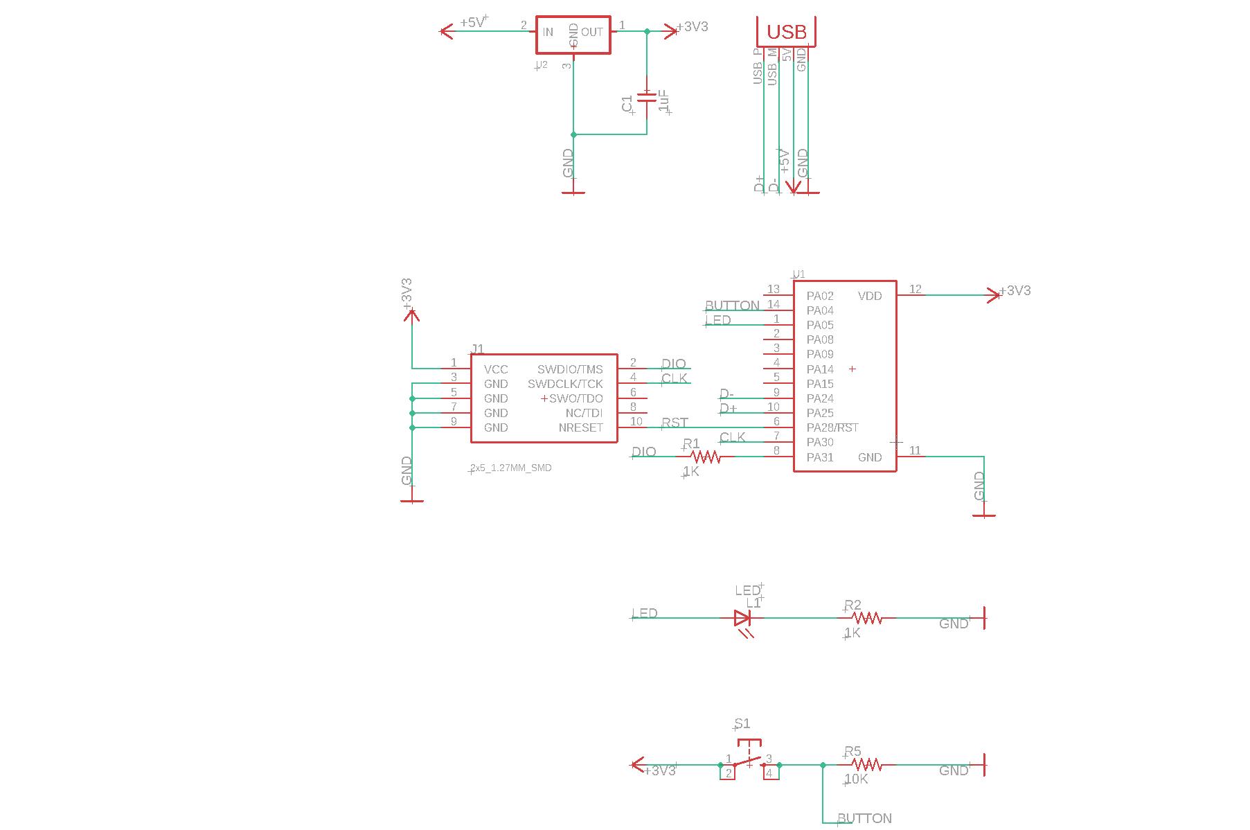
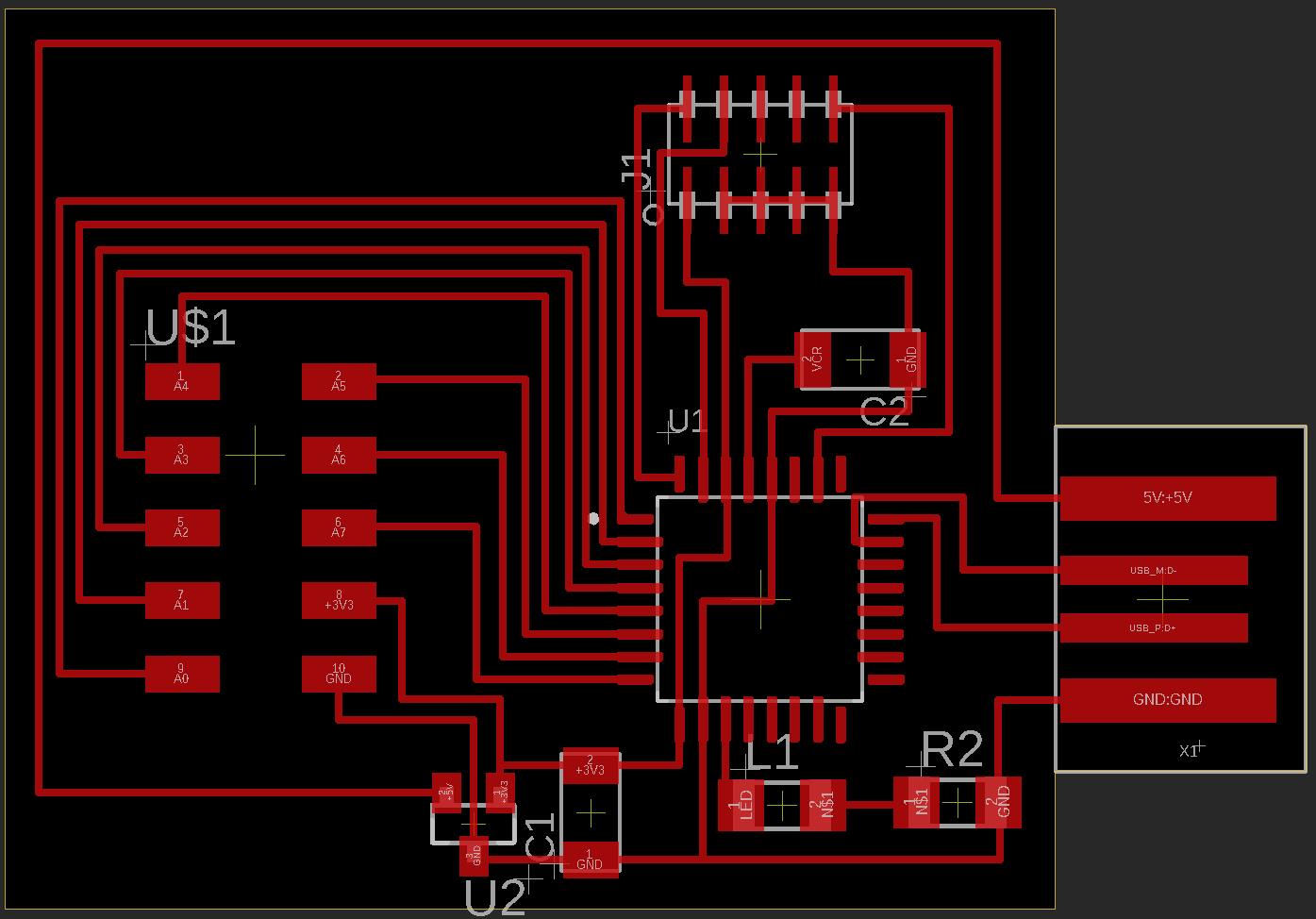
Since I have experience of using D11C, I choose D11C-echo-10 as a reference. I first finish the base drawing according to the material provided by the teaching team. Then I started to add the LED and the button. For LED I simply connect it with a resistor to limit the current. According to my experience, I chose a 1K resistor. As for the button, I designed a structure which is energy efficient: when the button is not pressed, there will be no current for button branch; whenever the button is pressed, there will be current and the button signal will be in high position.
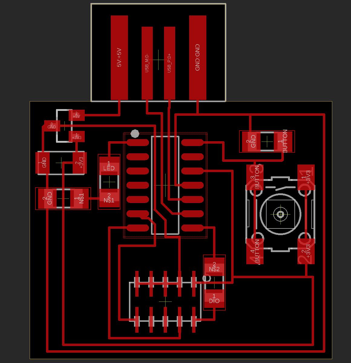
Then I started to design the PCB board. No matter how I place the components, I have to use a 0 ohm resistor. Besides, the default clearance doesn't allow me to put 4 traces under the D11C. I have to change the width of the trace to design my board. For the rest part of the board, it is quite straightforward.
After that, I basically follow what I did in week 2 to fabricate the PCB and solder those components. For this time, I optimize my procedure of soldering them according to the height and place. I first solder the component in the center which is lower, then solder the rest. In such a case it is easier for me to solder the components.
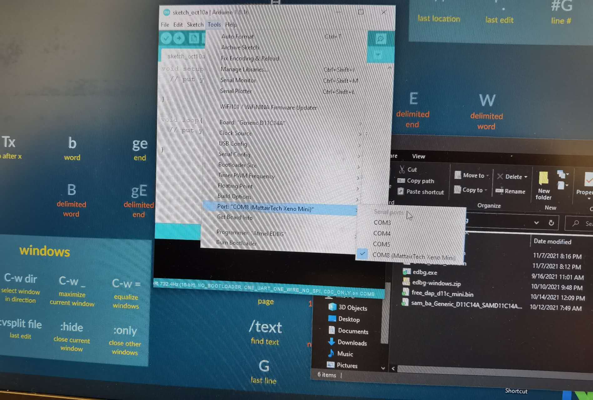
The TA said that normally people have problem after connecting the PCB board with the computer. Sometimes the Arduino IDE just cannot detect the board. For my case it seems that everything went very well. The Arduino can detect the board, and succeeded in uploading the scripts, and the LED lighted well.
Week 5 CAM
Group Assignment
Individual Assignment
For this week I mainly learned how to make something big (about 1 meter) using wood. Recently I bought a large table where I put my monitors and keyboard on it. To better utilize the space, I believe that a monitor riser is needed. So I decided to design one and make it.
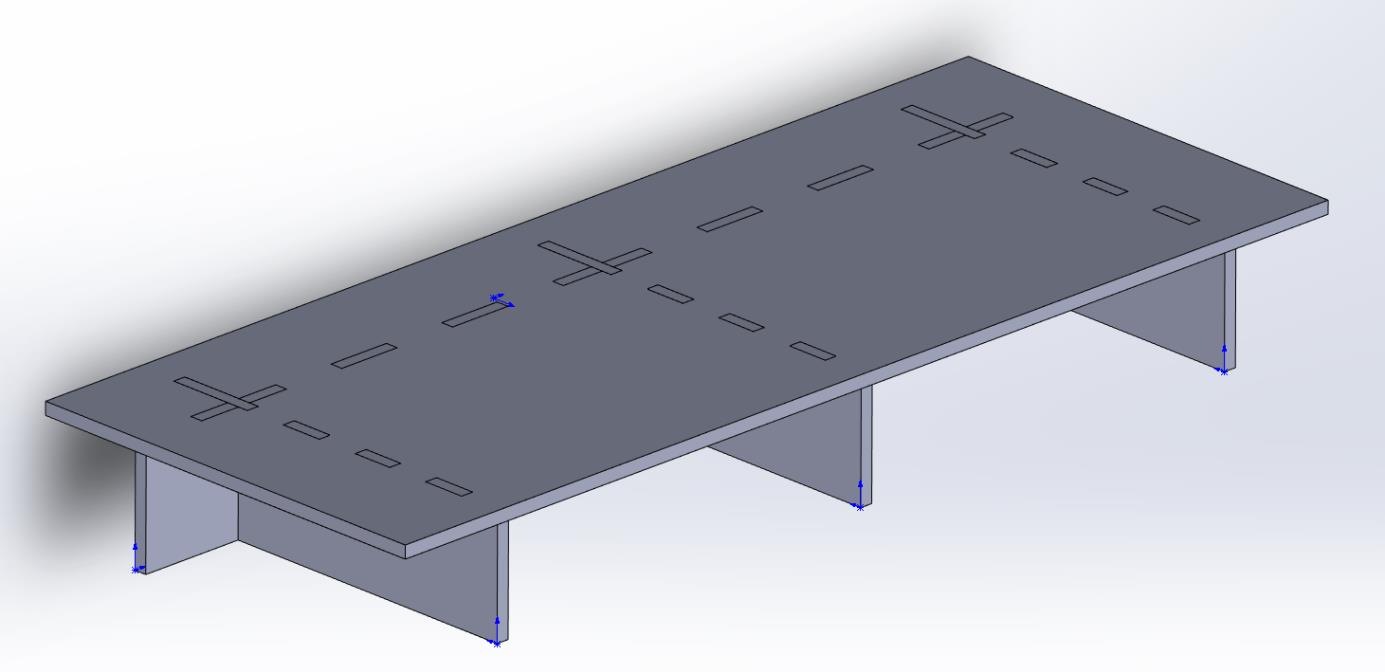
One thing which requires special attention is the size of the holes. According to the group session I had, I learned that the thickness of the board varies between .45 and .47 inches. As a result, I took the mean value as the size of connections. In addition, to prevent the arc for the inner corner. I need to add another layer and place holes at the corners. (This is something I did not do so I have to manually add it in the MasterCam)
Chris helped me a lot regarding the tool path. There are 3 paths used to cut the board: 1, corners; 2, inner holes; 3, exteriors.
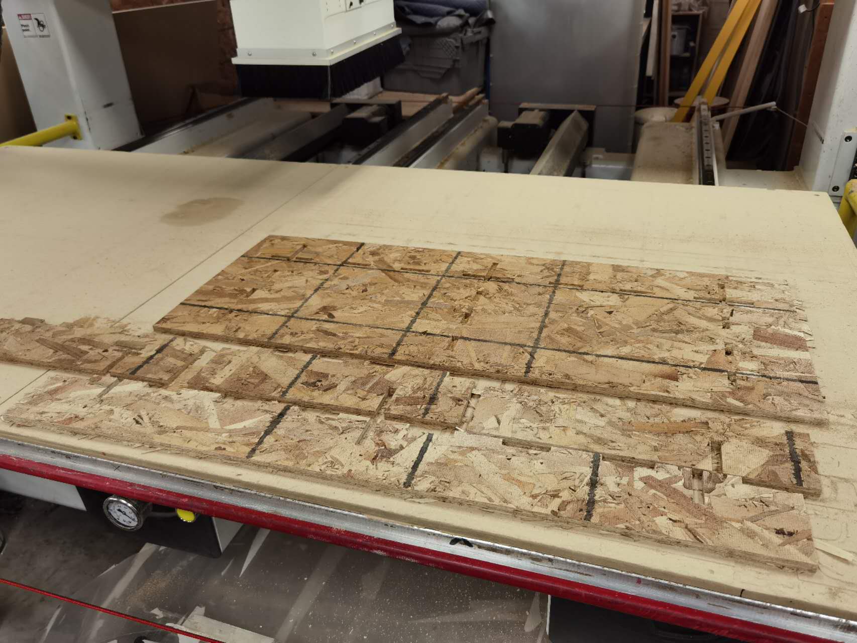
A key thing I learned while fabricating it is the vacuum. I should always turn the vacuum on while drilling the wood. Otherwise the powder will harm me.
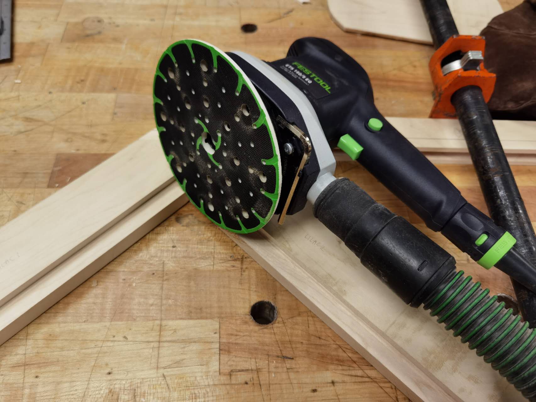
After having the fabricated wood, I really want to make the surface perfect. As a result, I asked help from Chris and got this machine. Starting from 60, I gradually increase the number of sand. Finally I got a very smooth surface
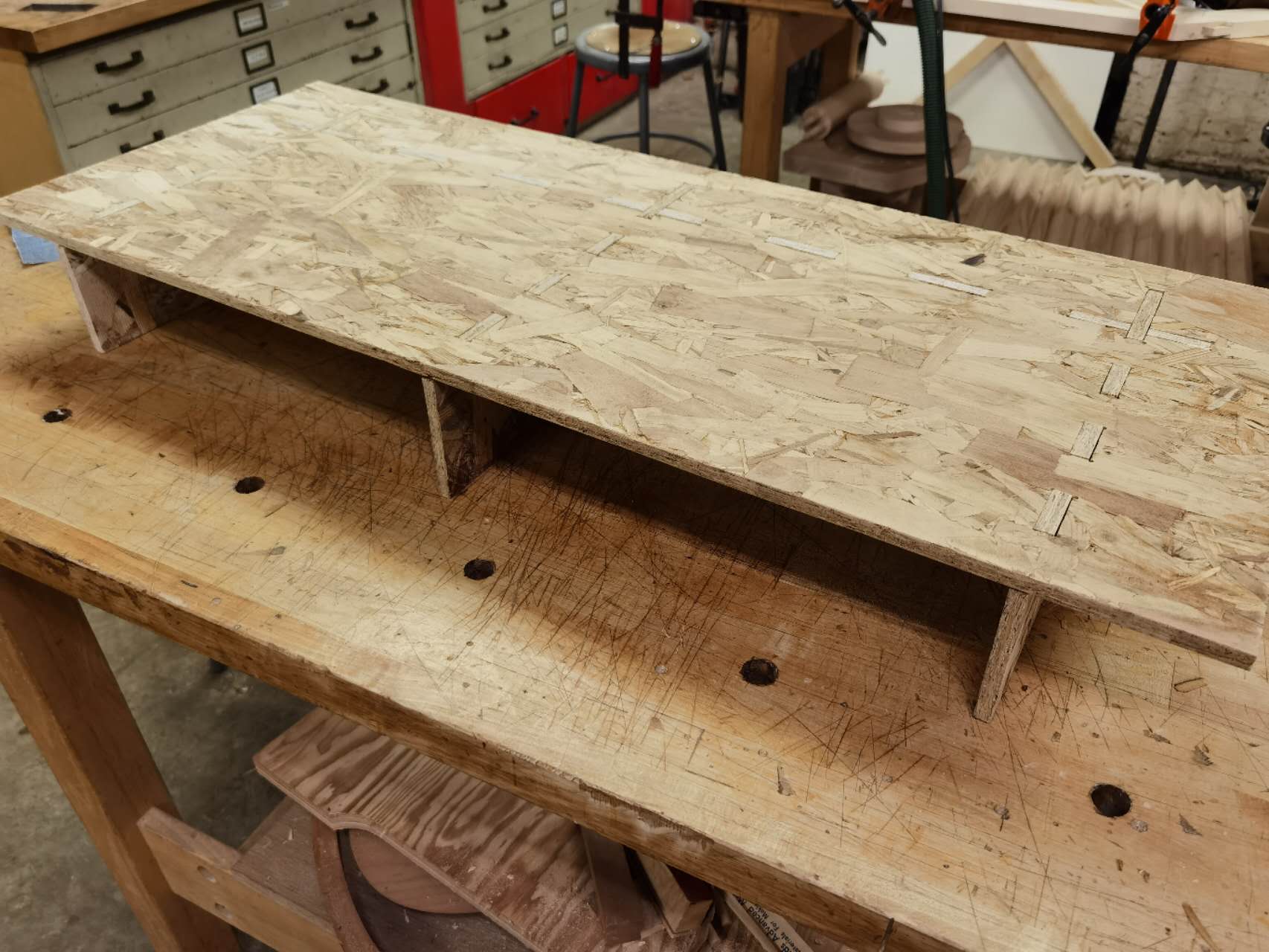
For this riser, I didn't use any glue. The thickness works perfect. I can easily use a hammer to assemble everything together.
By the way, this is the group product we made:
Week 6 Embedded programming
Group Assignment
Individual Assignment
This week's assignment is something I am very familiar with, since my bachelor degree is Automation and I played Mega 2560 a lot in the past. When I tried to upload my code to the board, the key difficulty I had was that Arduino IDE version 2 cannot recognize the board. It seems that IDE version 2 doesn't have the corresponding library. So I have to downgrade the IDE version and install libraries according to this link.
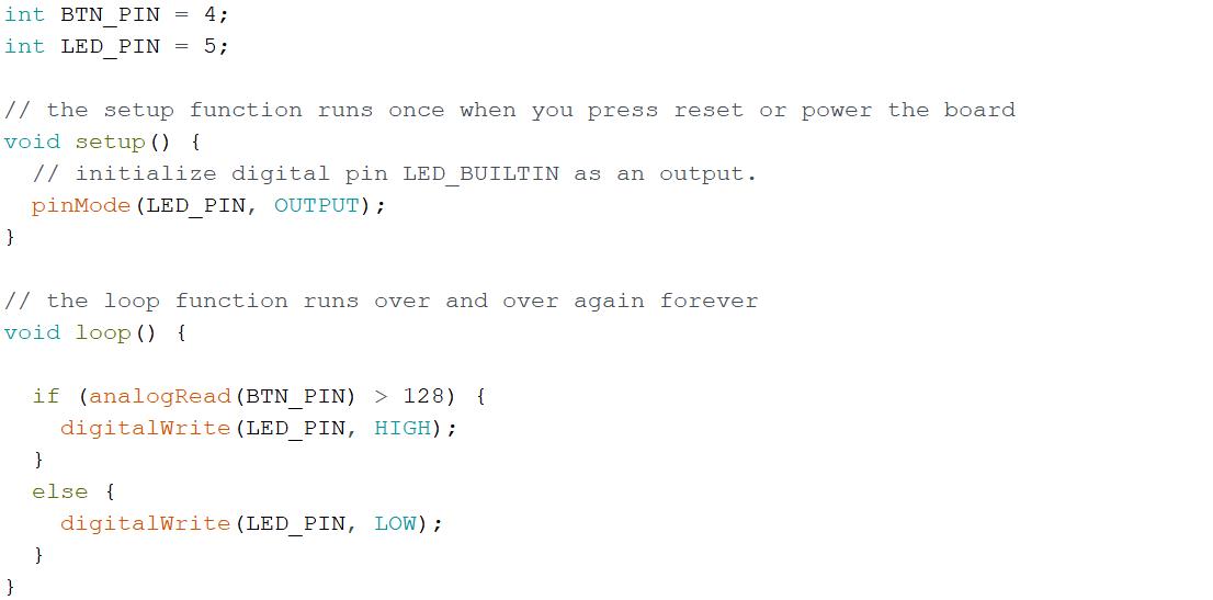
I designed a program logic which involves an input component (button) and an output component (LED). Whenever the button is pressed, the LED will light up. My personal habit is to test each component individually and then integrate them together. The LED works very well when I use the digitalWrite function. However, no matter how I use digitalRead function to read the button, I just can't go into the logic I want. After checking the pin map of D11C, I suddenly noticed that the button was connected with a analog pin. After changing into analogRead, I successfully read the value of the button.
The demo video can be seen here:
Week 7 Mold & Casting
Group Assignment
Individual Assignment
This week is quite intense. There are a lot of new things to learn and a lot of works to do. I am very happy that I make it in the given week!!!
As the very first step, I joined Jen's one-on-one session to go over the molds produced in the past. Besides the normal procedure, the most important lesson I learned is that I cannot make something very small due to the limitation of the milling machine and I should design the air hole since the material is very sticky. I optimized my design right away.
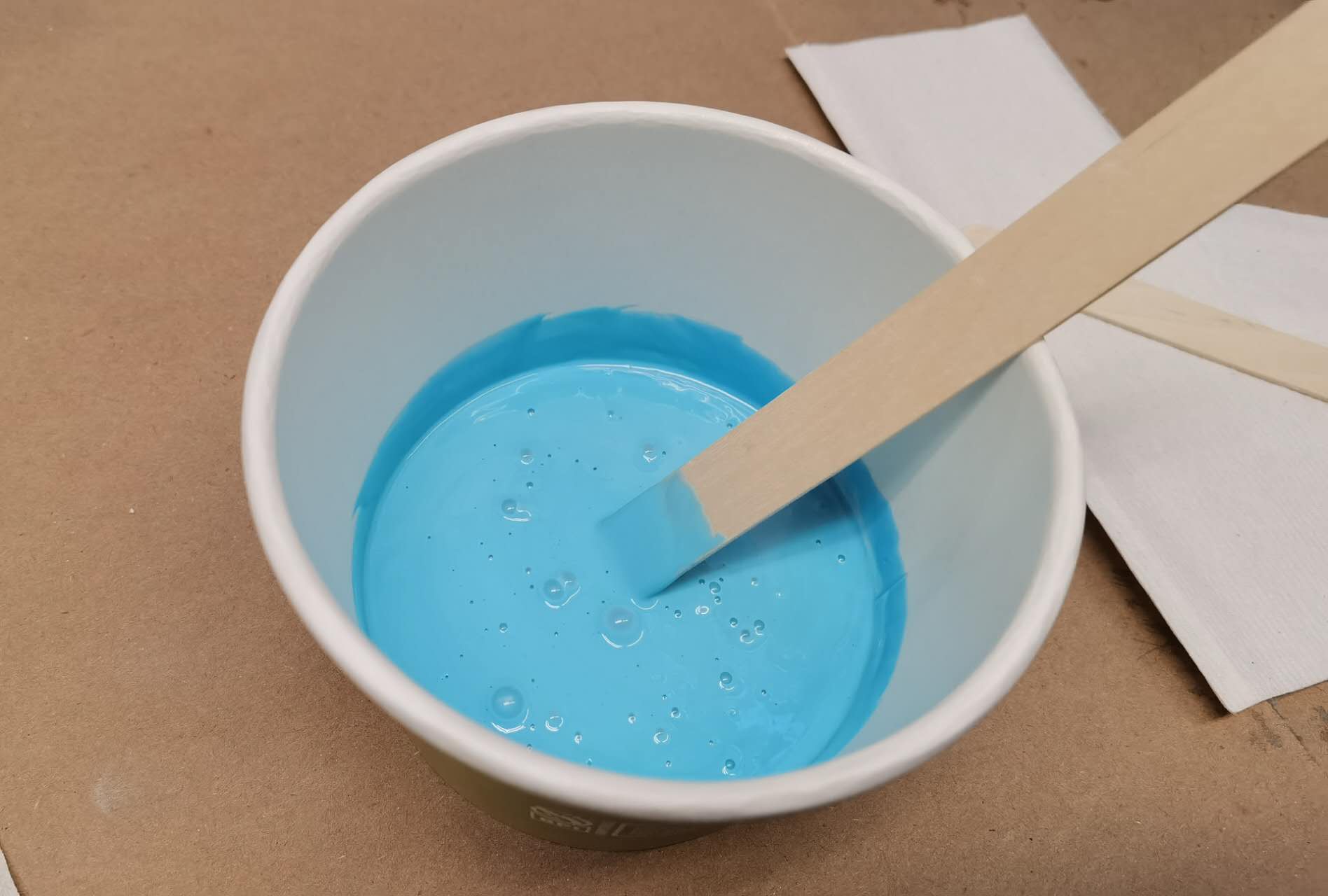
I also joined the group assignment to get familiar with the actual fabrication. As we are coping with chemistry, I want to be 100% sure about how I should operate. It is good to know that for two different sets of material, the pot time are different. (Oozo is 15 minutes while the other one is 25 minutes)
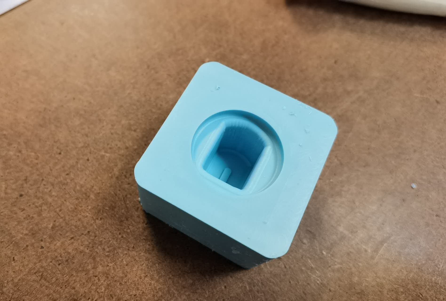
As a try for this week, I am thinking of making a knob of airplanes. As you can see in the picture below, I design it and specially design a small detail on it
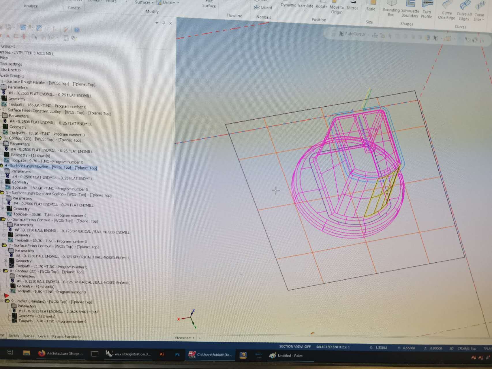
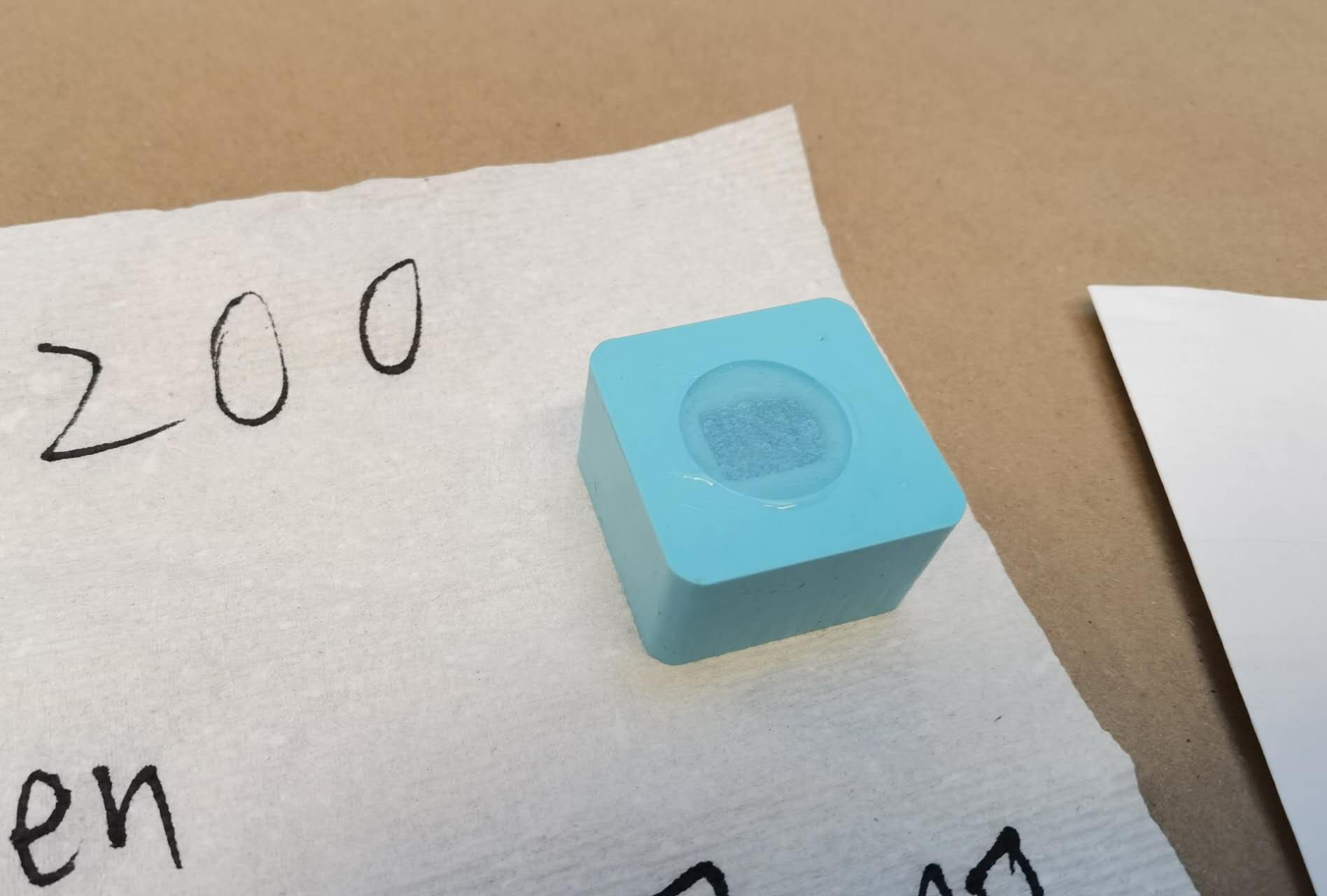
I got a lot of help from Jen in this week. From the design, to MasterCam settings, to actual milling. You can see the steps below
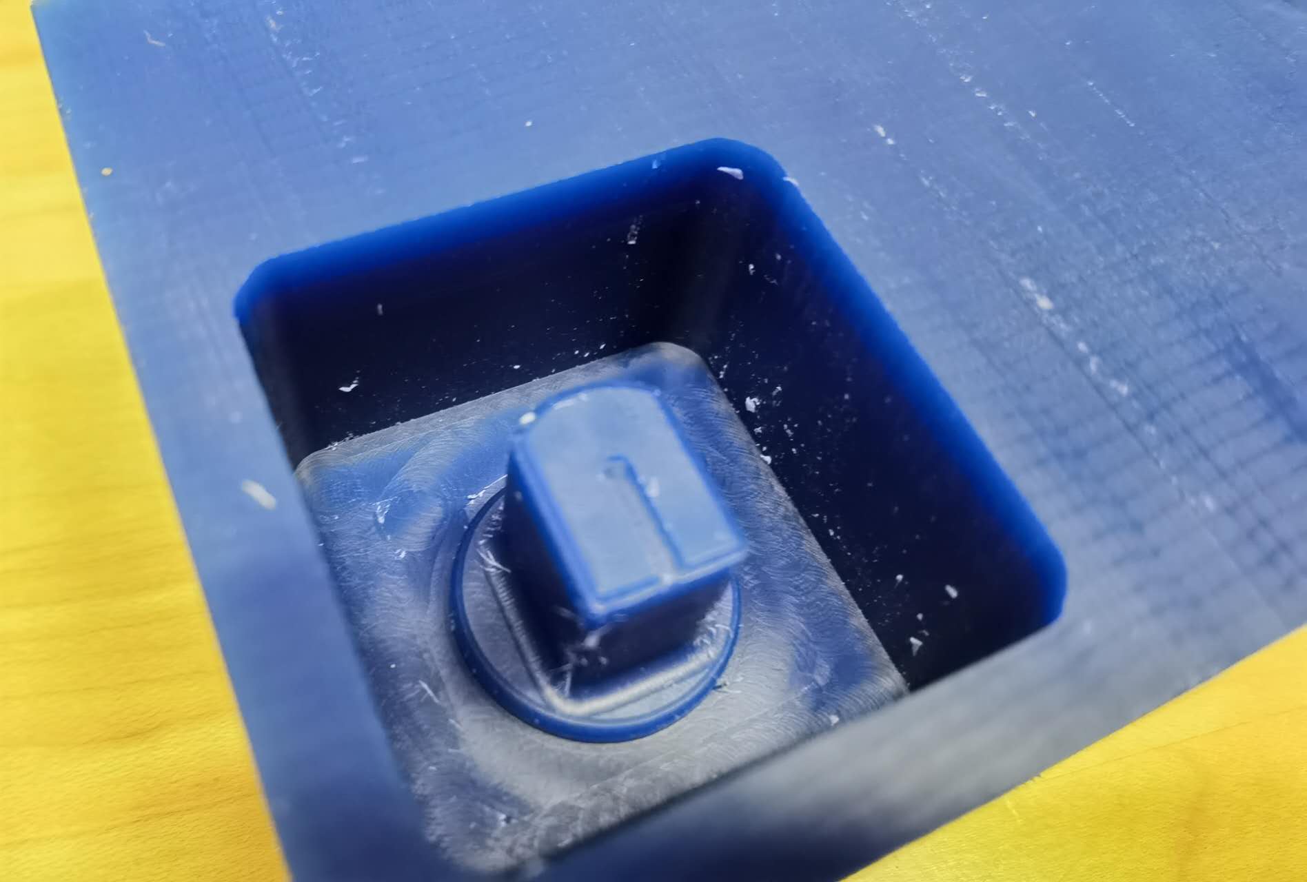
One thing I noticed about my casting is that until the time that I write this log, the knob still feels sticky and soft. It seems that this material has a different solid time compared to oozo.
Week 8 input device
Group Assignment
Individual Assignment
This week I learned about different input components. With these sensors, my circuit is able to process more complex functions.
As there is no clear requirement that I have to design a new board. I plan to add a sensor to my existing board. For this one, I would like to add a temperature sensor.
After reading the datasheet of NTC, I understand that this sensor is a temperature sensitive resistor. As the temperature goes up, the resistance will drop. So I can have a mapping from the measured voltage to temperature. Thus, I can have the temperature readings.
To mount with my existing board, I use jump wires to connect the sensor with my board
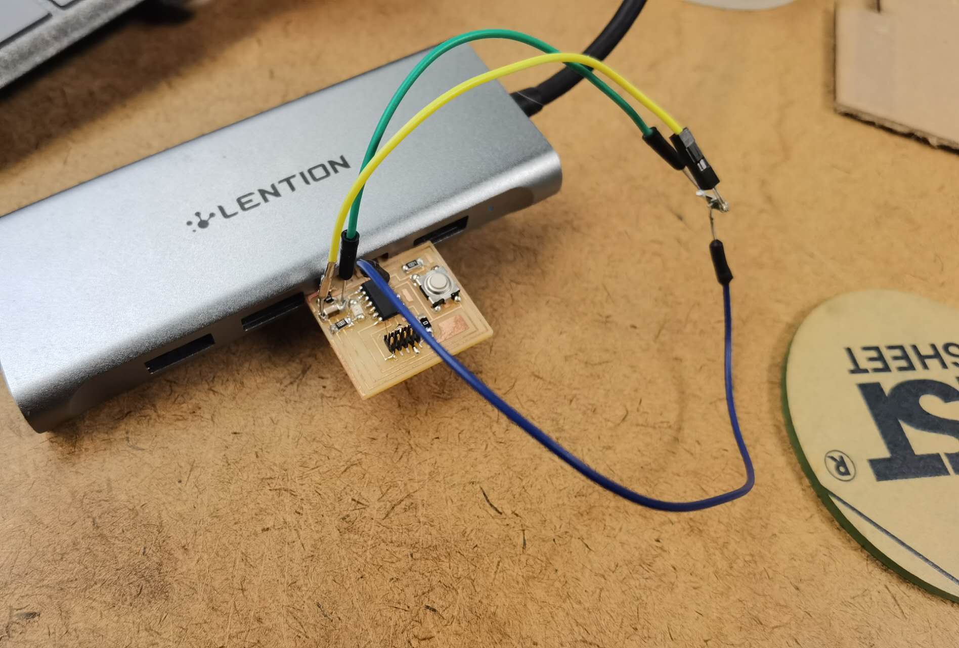
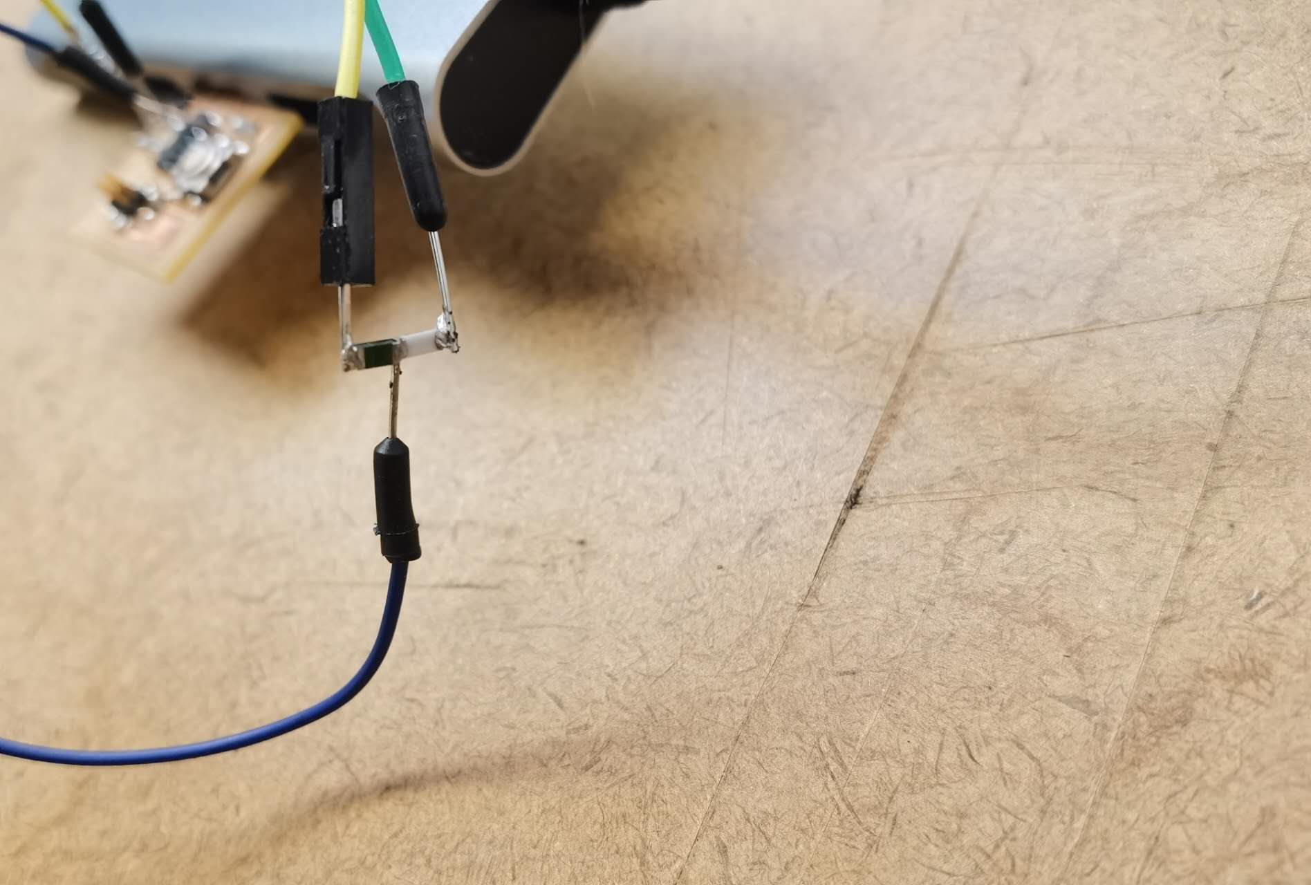
I use an analog pin to read the level of voltage. I use a 10K resistor to split the voltage together with the temperature sensor.
As you can see here, when putting under the room temperature, the reading is about 500. Whenever I touch the surface of the sensor, the reading drops quickly.
I put the sensor in my refrigerator, into a boiled water and in the room. I get the following mapping curve:
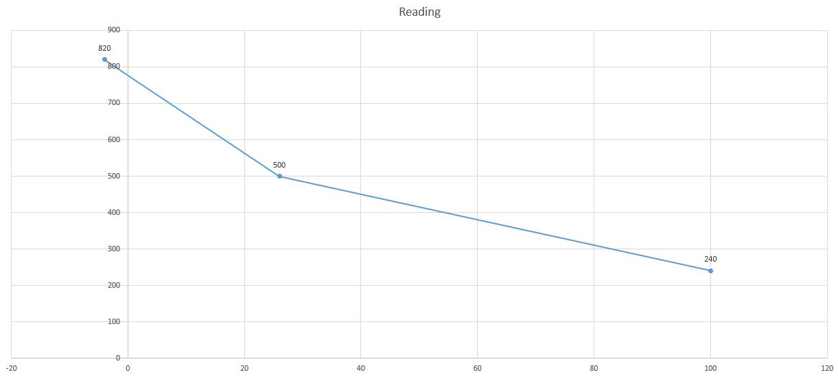
Now thinking about the temperature of my finger (reading is about 450), the temperature should be around 38°, which is reasonable.
Week 9 output device
Group Assignment
Individual Assignment
Thinking of my big project which will involves a lot of LEDs, I decided to use LED as the output.
At the very beginning, I planned to design a modular motherboard which has the main chip and many pins that can easily connect with different LEDs. For this design, I choose to use D21, which is proven to be a wrong decision later.
I feel confident about my design. However, the problem is the fabrication. Soldering the D21 is never an easy task. I tried my best to solder it but finally failed. Instead of using the normal soldering iron, I should use the hot air gun.
Although my trial for making a motherboard fails, I succeeded in LED controls. For my big project, I am thinking of using LEDs as the source of backlit. One main function I should implement is the adjustment of the light intensity. There are two ways to achieve that
- First, I can have a slider resistor. Whenever needed, I can adjust the resistance so the LED will gain different current.
- Second, I can adjust the frequency of PWM voltage thus the light intensity will change accordingly.
After considering about the flexibility, I decided to take the second approach.
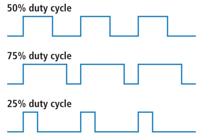
Using PWM to control the light intensity, I can adjust the duty cycle. And at the same time, I need to make sure that the frequency of the switch meets the requirement of human eyes. Otherwise I can feel the blinks.
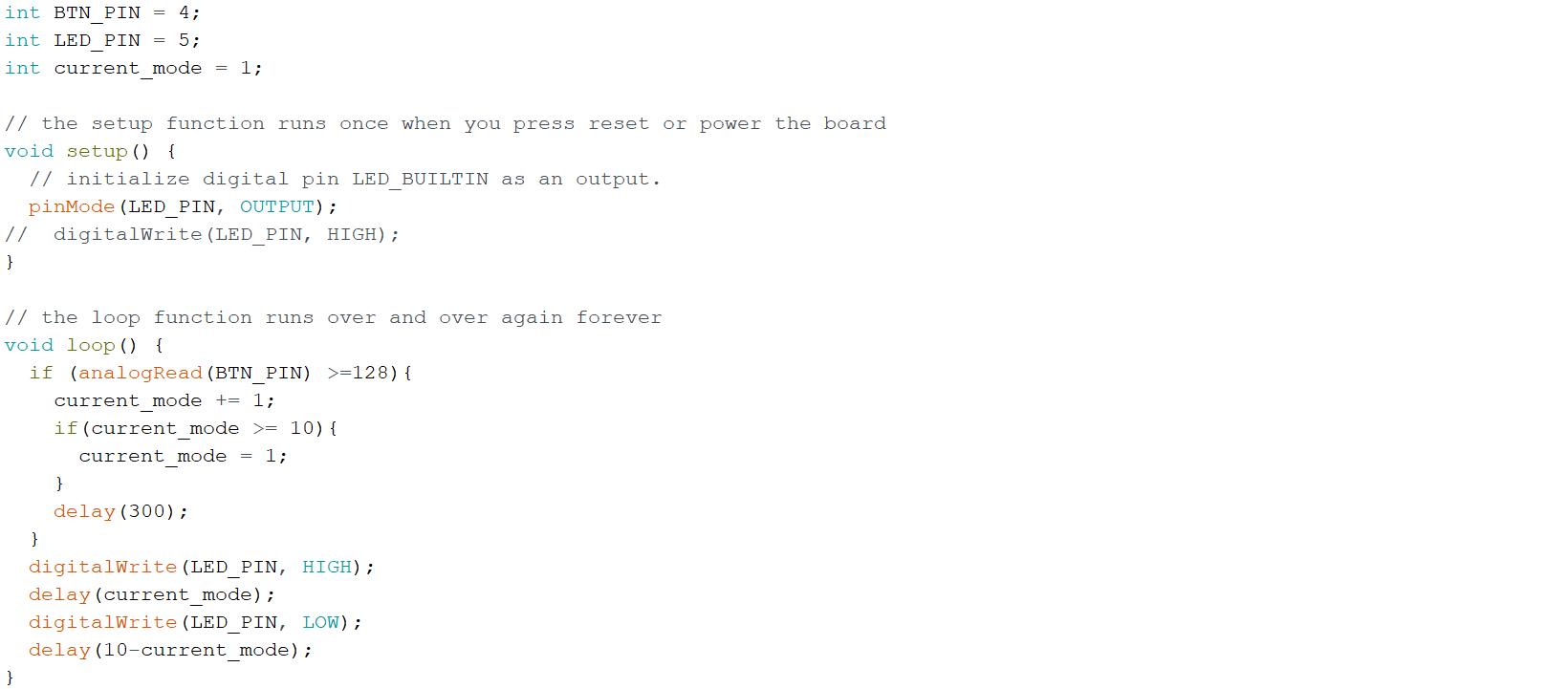
With the previous script, you can see the change of light intensity after pressing the button. I can use this as a way to adjust the light of my cockpit.
Week 10 network
Group Assignment
Individual Assignment
Communication between chips is definitely something very important. For this week, I first complete my motherboard design and fabrication and do some experiments regarding the serial port communication
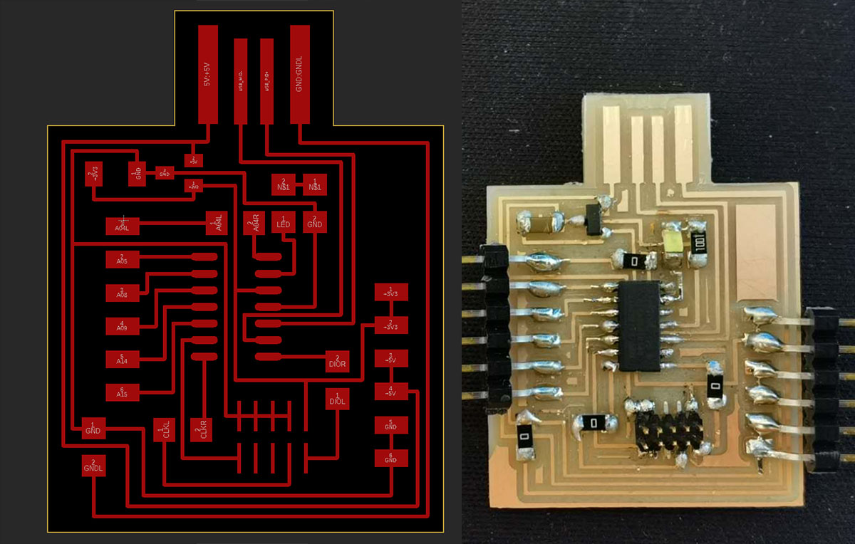
For this motherboard, I reserve two ACC, 3.3V and GND pins which allows me to output the power or to get input power. Besides, I also export 6 pins which can be used as digital/analog pins or being serial ports.
The first experiment I have is to test the one board communication. According to my script development, whenever the board receives "1" (i.e., 0x31), the light should turn on and return "Light on" back to the computer. As you can see below, it works well:
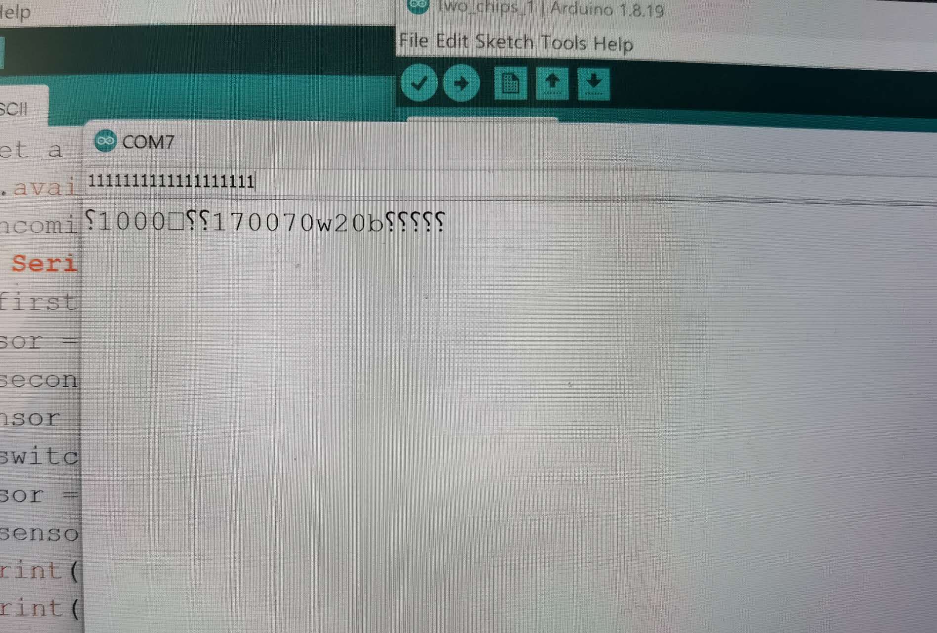
The second experiment I have is to test the one board communication with multiple serial ports. I make a connection wire and then use a jump wire to link the tx and rx pin. So the signal will pass from Serial port to Serial port 1 and go back to Serial port. However, the result is not good. I send out "11111" but get weird returns. I suspect it is the problem of signal transfer.
The third experiment I have is to test the two boards communication. I have two identical motherboard and I use the connection wire to connect their serial port 1. Then, I can send the signal to board 1 to control the on and off of LED on the board 2:
Week 11 interface
Group Assignment
Individual Assignment
This week we finally come to something I am very familiar with: software!
In the previous week, I designed a board which can use the serial port to control the light on and off. So, for this week, I plan to develop an interface which can communicate with my board
As currently I am fluent in Python and I have used Qt in the past, I chose to PyQt as the package to build my application
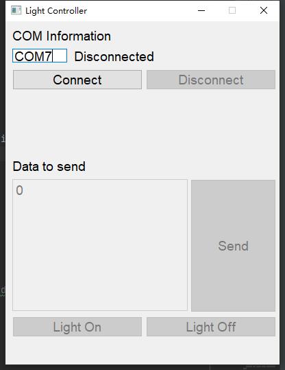
In the screenshot, you can see my design. There are two separate areas. The upper part is the place to specify the serial port you want to connect with. The buttons are mutually excluded. The connect button is enabled when the current status of the port is disconnected. To help me understand the current status of the port, I also have a status text showing the current status.
The lower part is the data sending area. Whenever the 'Connect' button is pressed and the port is successfully open, all lower parts will be enabled. There are two ways to control the light: first, you can hit 'Light On' button or 'Light Off' button; second, you can write down the data you want to send and hit 'send' button. I believe this is a good way to fix the command I want to send while reserving the freedom for me to add new commands and do the test.
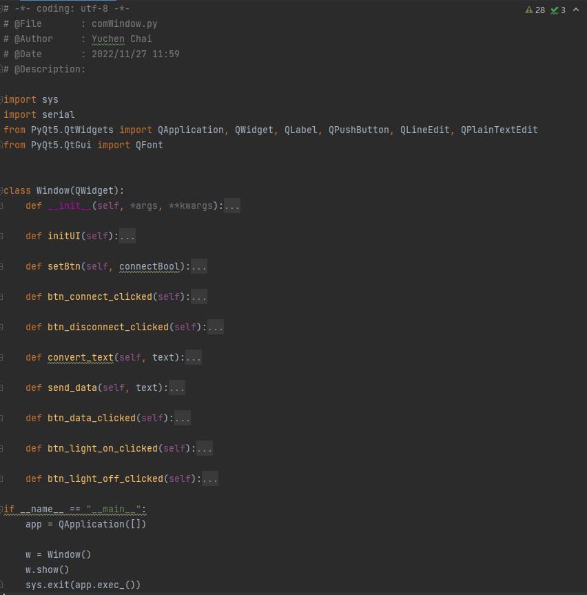
My code is relatively easy to understand. Instead of using the interface drawing function, I implement the interface purely using the code.
It is time for the show and tell: as you can see in the video, I can connect with my serial port, and to let the light on and off by clicking buttons. Quite easy!
Week 12 Machine week
Group Assignment
Individual Assignment
For this week, I mainly work on the software team
First, I clone this repository: link
Then, I run the server with node.js
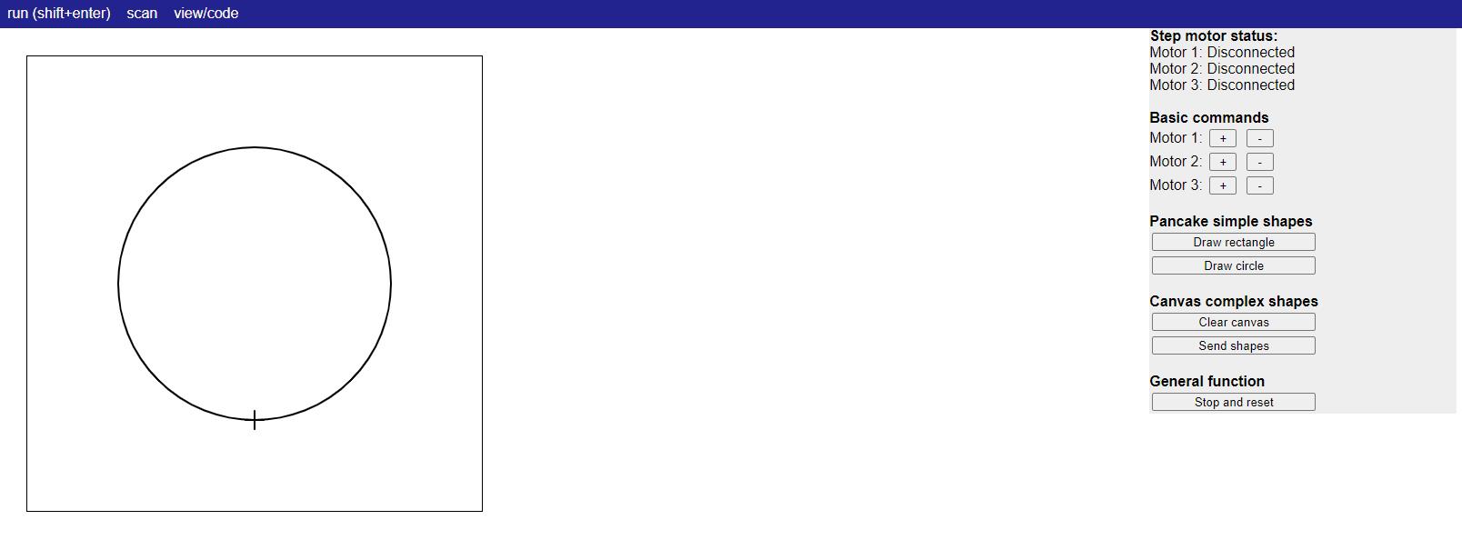
My task is mainly to develop the interface. I created the function panel with 3 layers:
- 1, Debugging tool: user can control the movement of the motor. Our team use this tool to test the connection to motors
- 2, Drawing tool: user can directly draw in the left canvas for the wanted shape
- 3, Command tool: user can send the current shape to the machine or clear the canvas and draw a new one
Week 13 Wildcard week
Group Assignment
None
Individual Assignment
Last weekend I volunteered a climate and real estate conference and was unfortunately infected COVID-19. Since Wednesday, I had to quarantined at home and missed almost all interesting training sessions. Luckily, I scheduled a separate session with Jen for the waterjet cutting after I recovered.
Due to the time limitation, I decided to make a simple design this week. I recalled the time that I wished to open a beer but cannot find the opener. So I decided to make one.
To decide the shape of the opener, I looked at my cat:
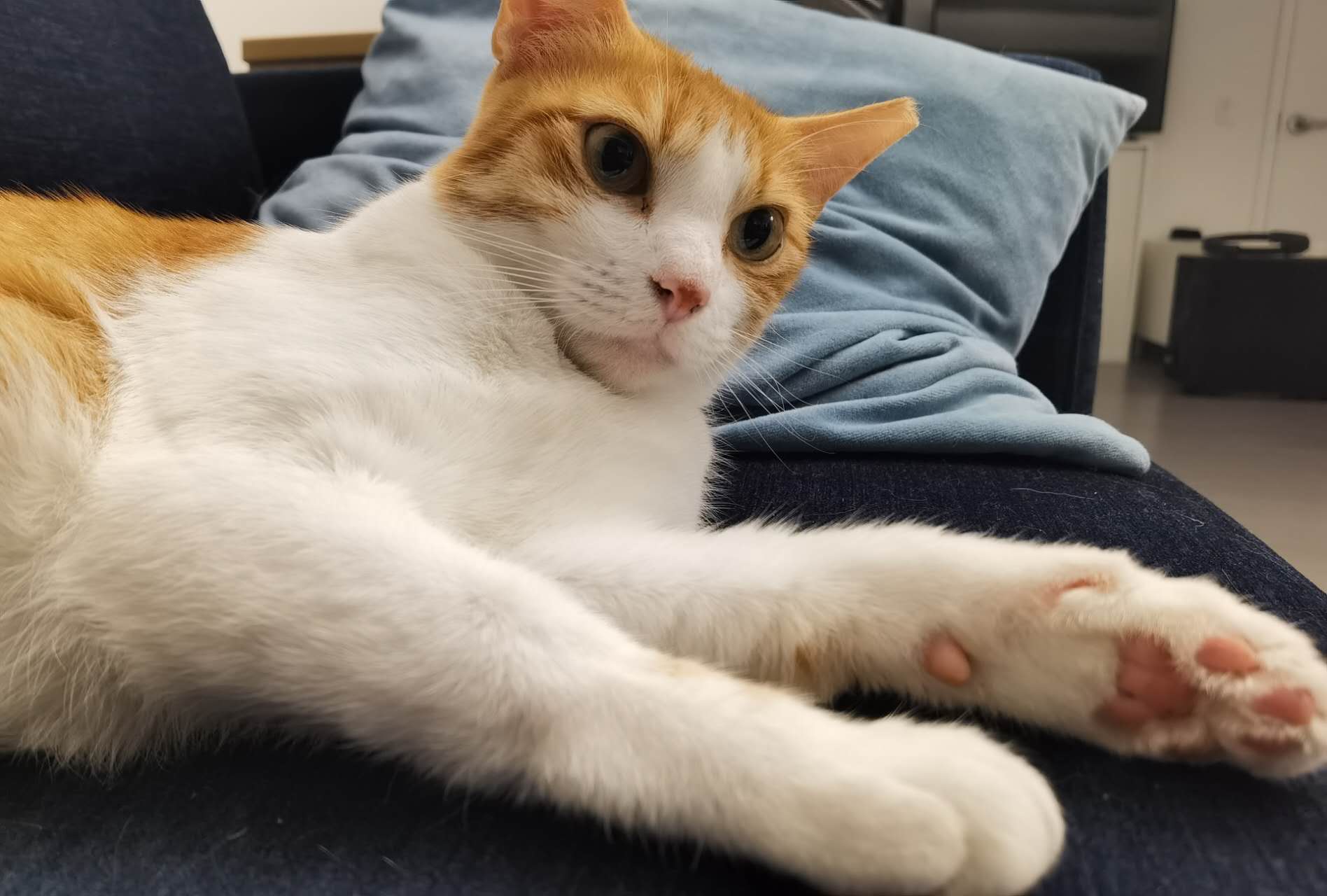
As you can see, the cat paw bottle opener is designed.
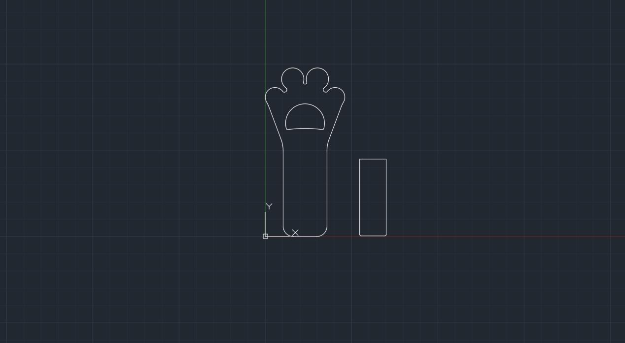
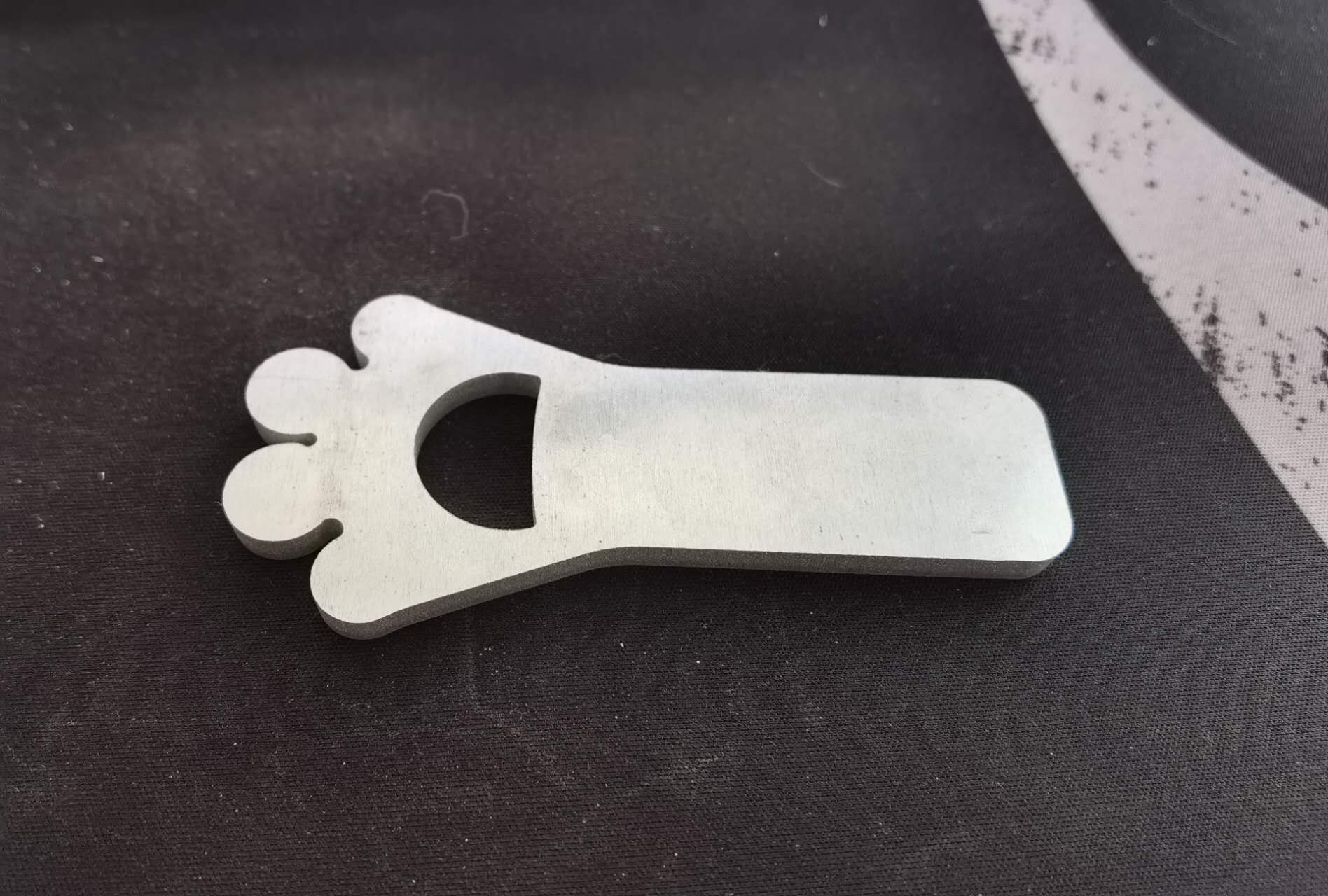
In case the small piece drops into the sink, I added a break to the small part. So that the part is not a closed curve any more. Instead, it is connected with the material sheet. And because of that, it is extremely difficult for me to remove it as this is a 5 mm thickness steel sheet. But you can see the main part below:
Currently I don't have beer at home, but I will buy one for the World Cup Final game. I will definitely give it a try of this opener.