Light Clock
Concept
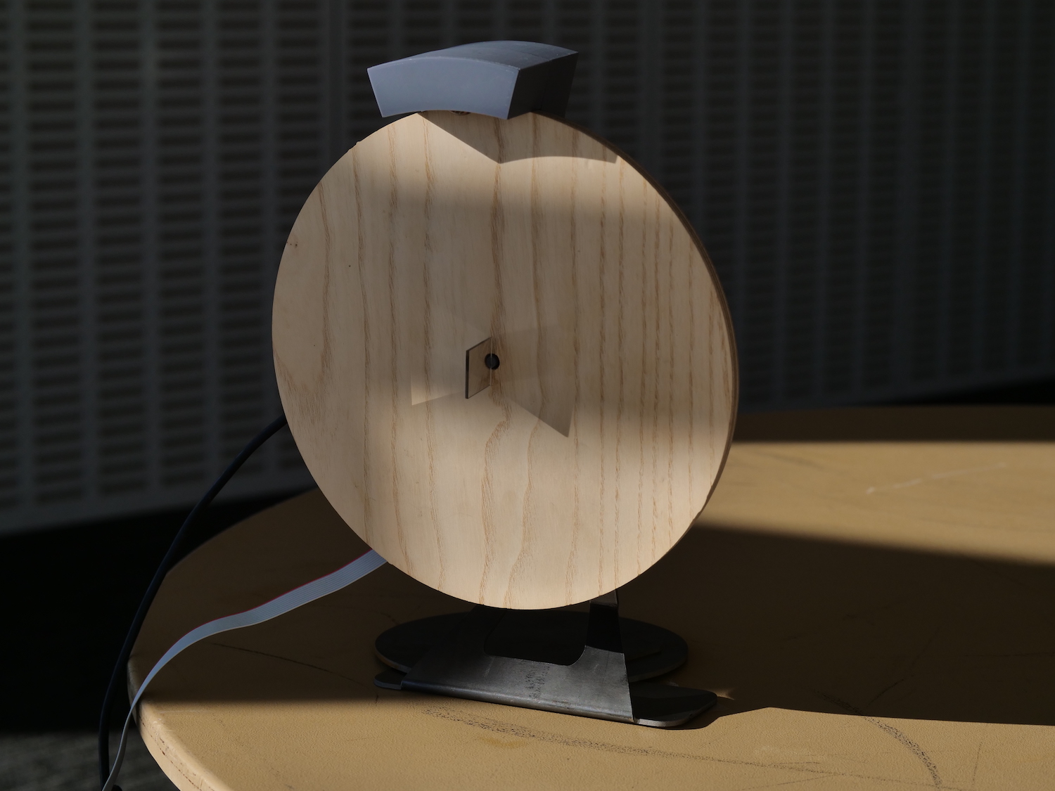
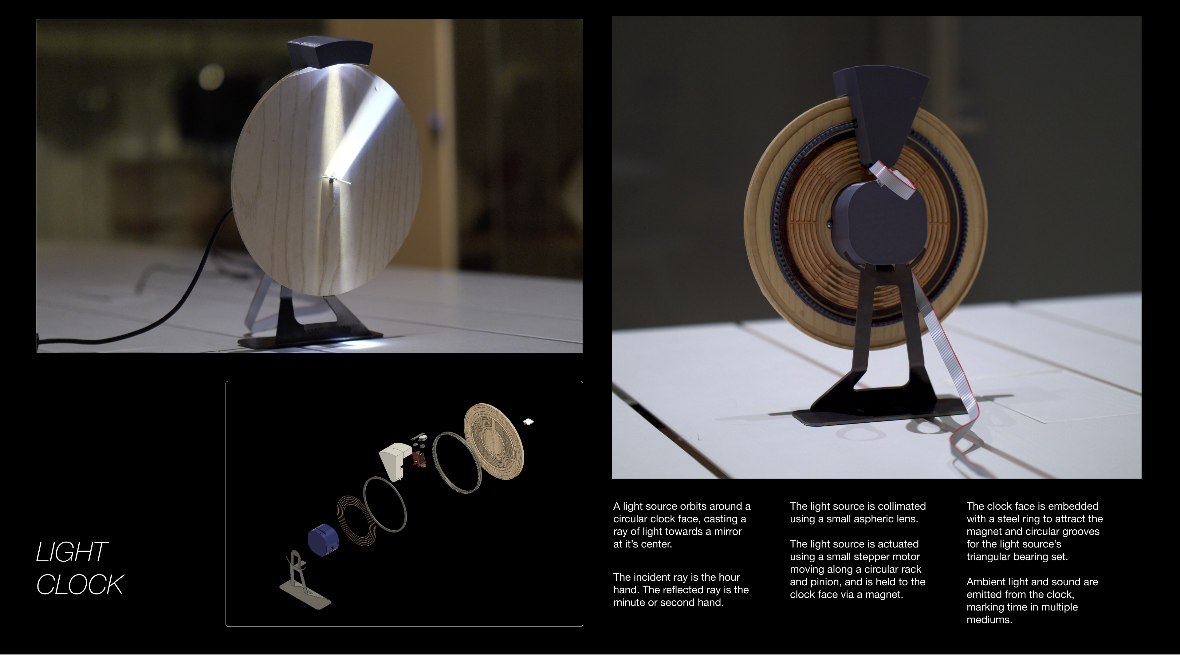
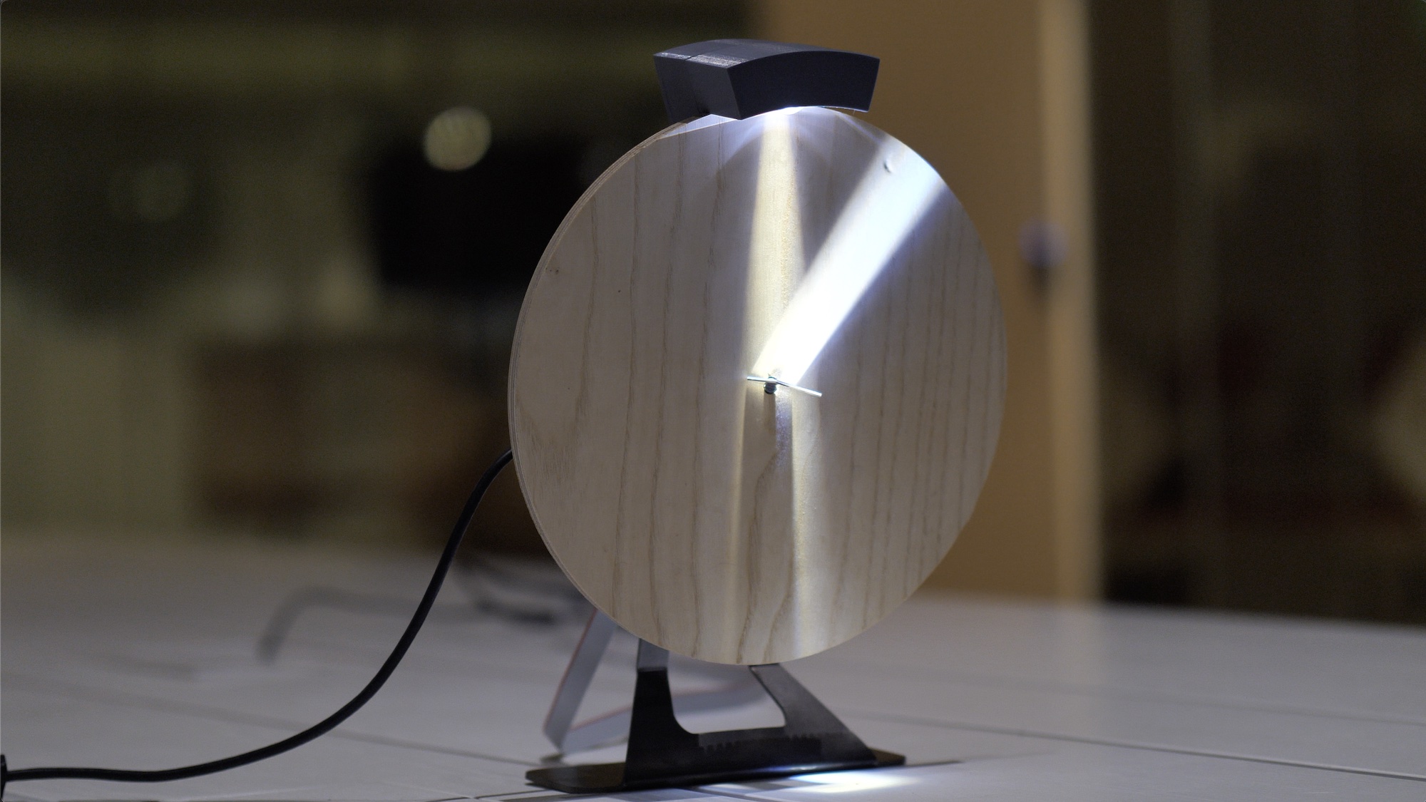
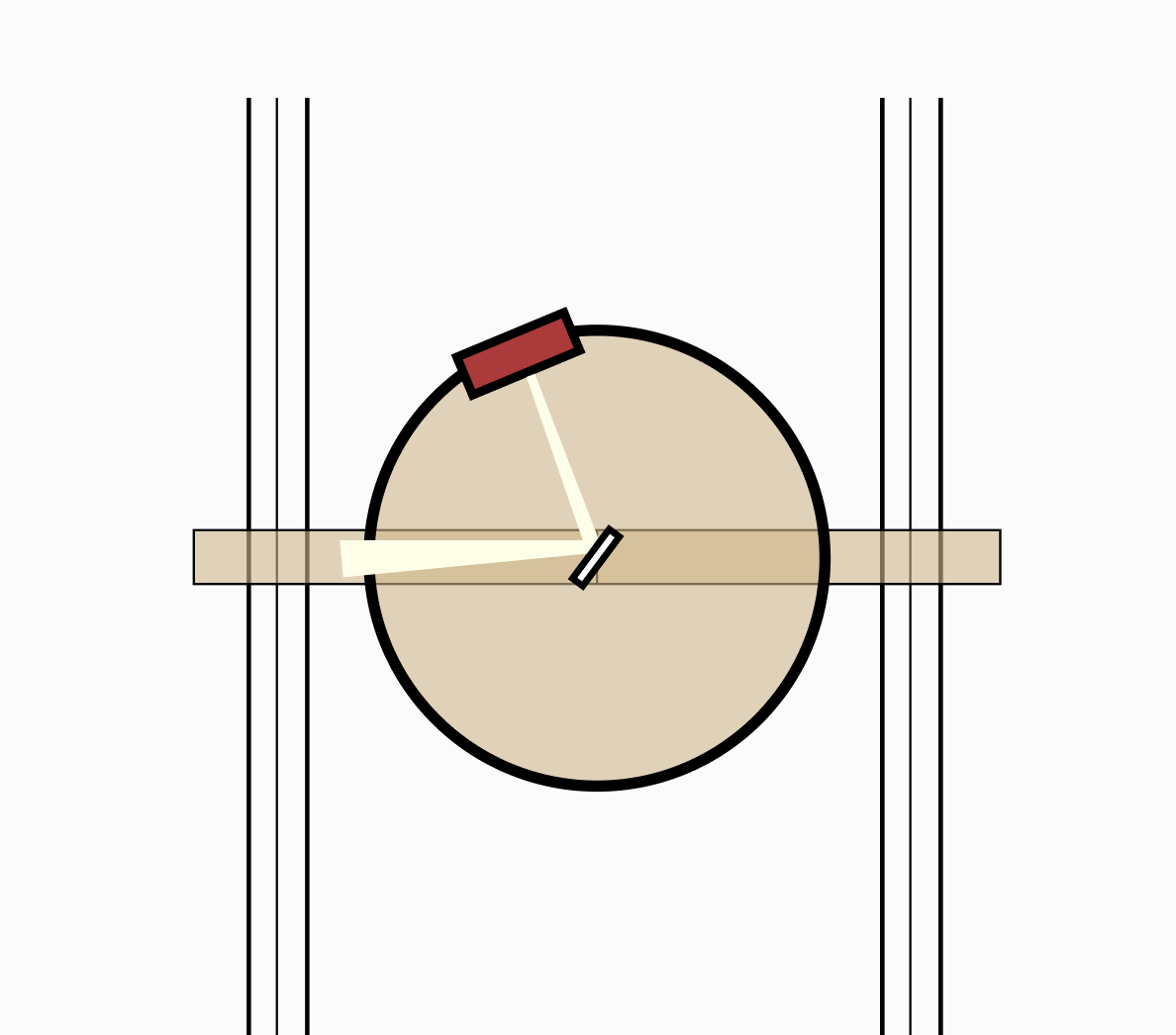
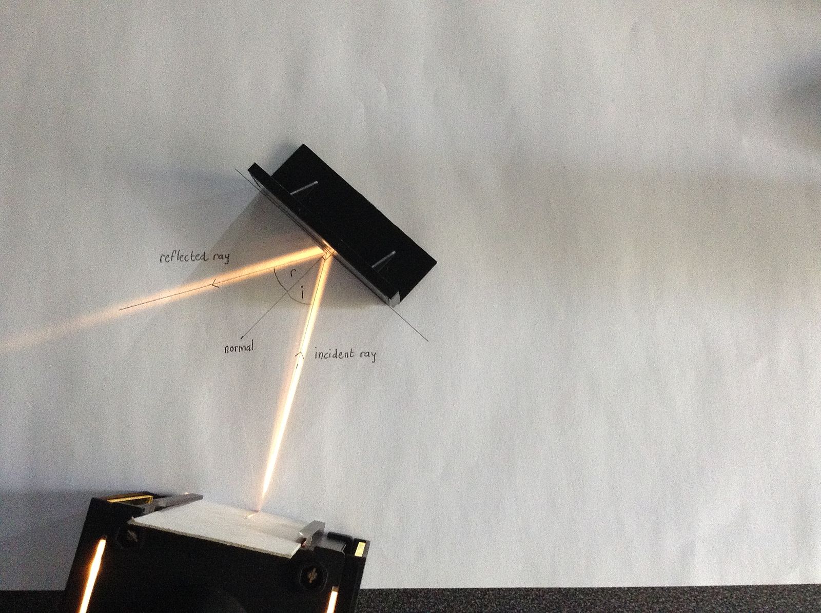
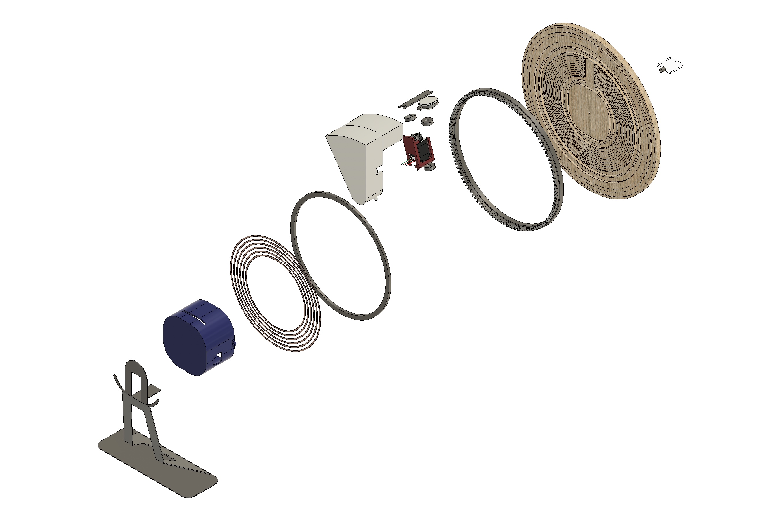
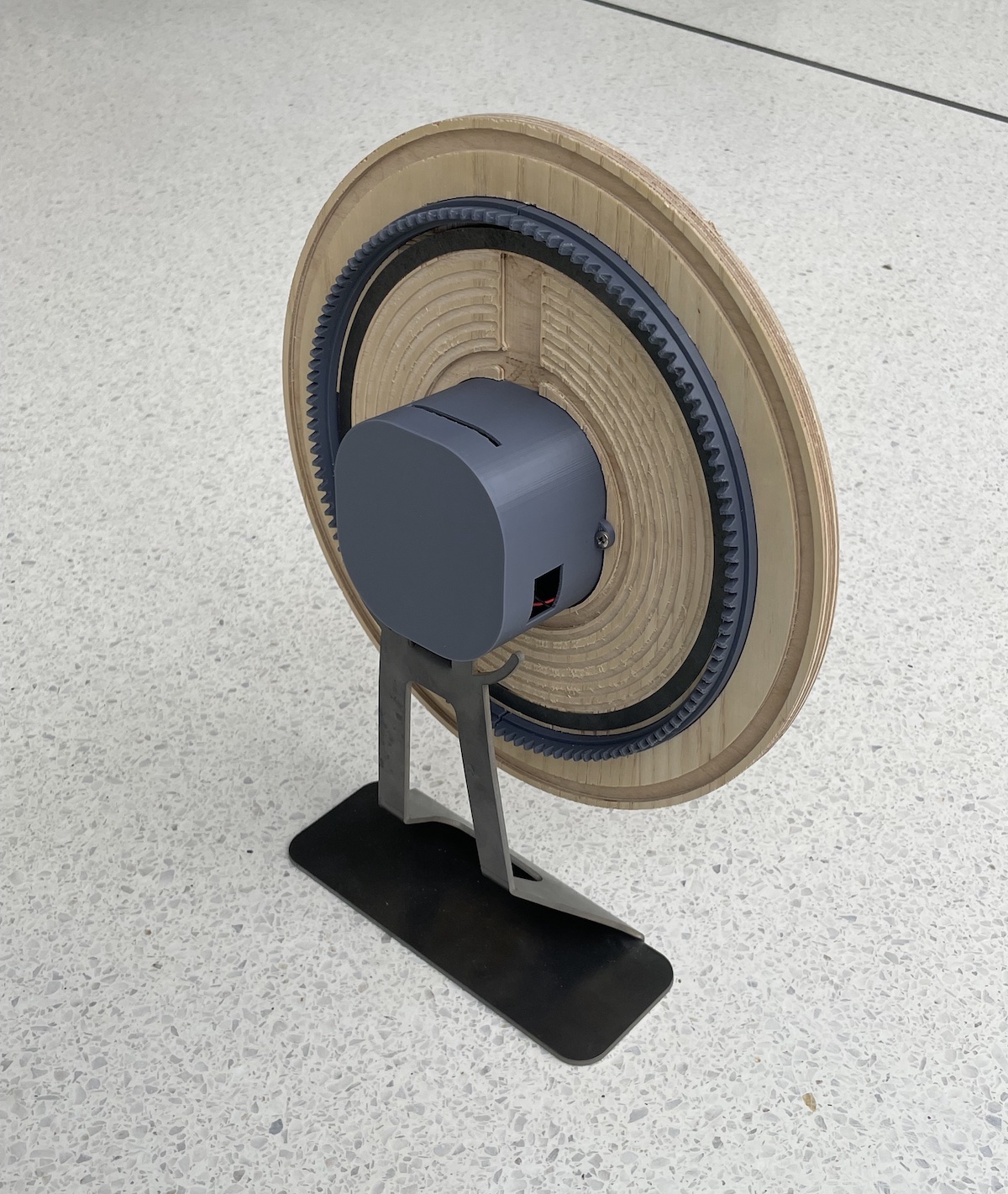
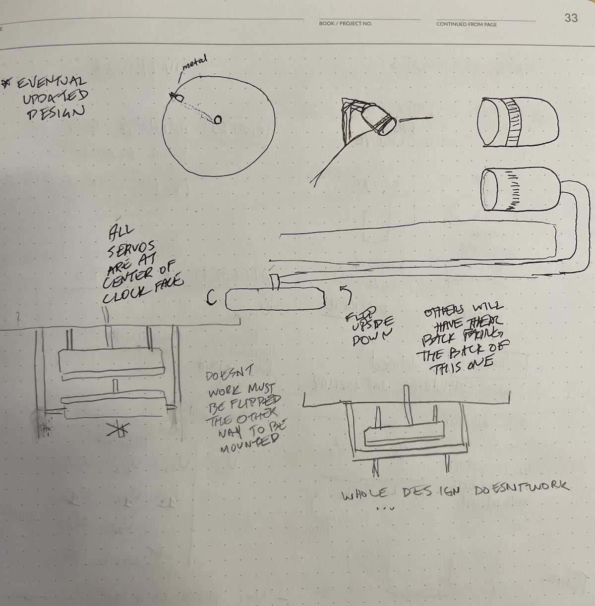
A stepper-actuated light source orbits on a circular track around a small planar mirror. The hour and minute arms of the clock are the incident and reflected beams of light emitted from the source and refracted off of the mirror.
• The light source orbits the perimeter of the clock face at a rate of one rotation every
12 hours.
• The mirror is double sided and rotates at a rate of 180 degrees every hour,
which enables it to reflect the beam of light representing
the minute hand at a constant rate of rotation.
• Light source makes a full orbit every 12 hours
• The mirror makes makes a half rotation every hour
• The mirror makes a full rotation every two hours
• The mirror rotates 6x as fast as the light source orbits the clock face
• At 12:30 or 6:00, the mirror is considered an infinitesmally thin surface and does not reflect any light,
allowing the beam to shine directly across the clock face.
Manufacturing
The was designed using five different primary materials and four different manufacturing processes:
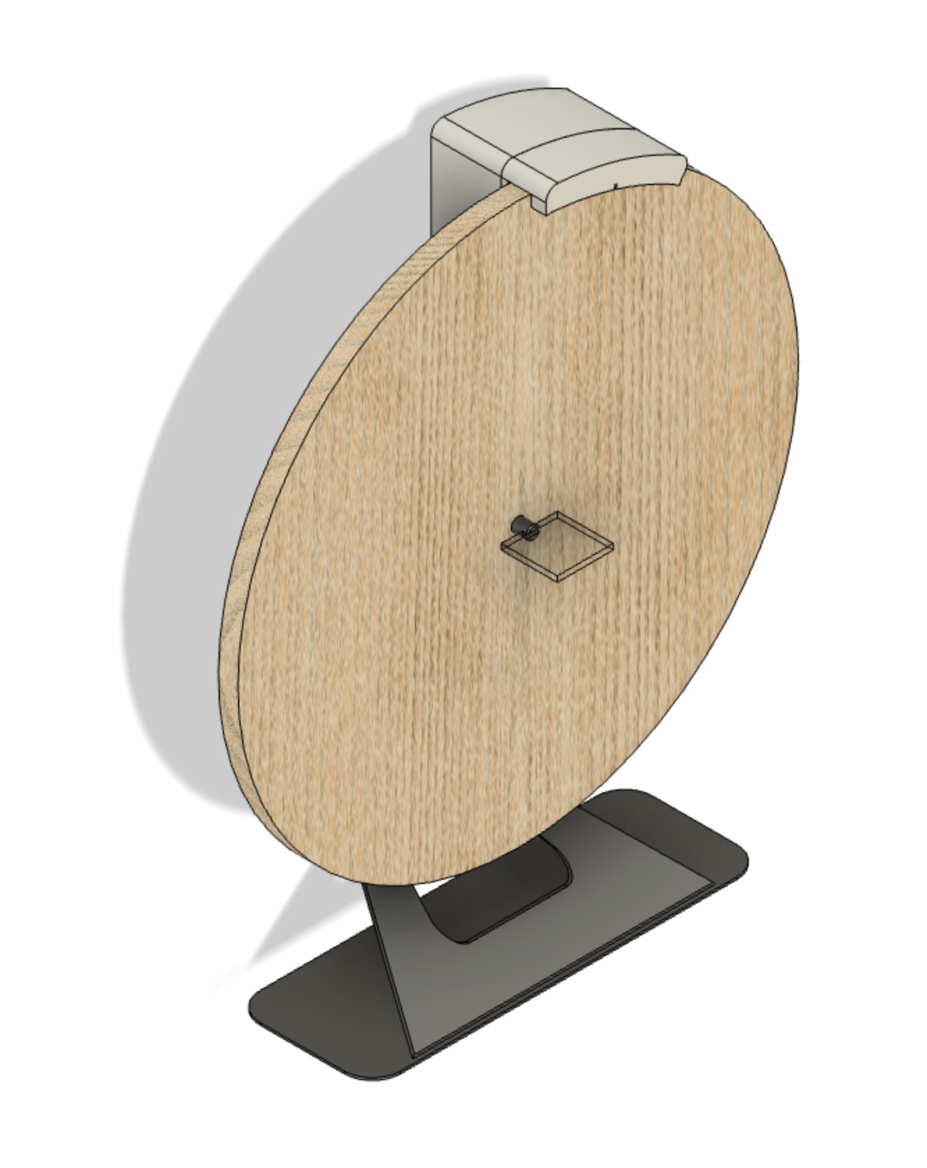
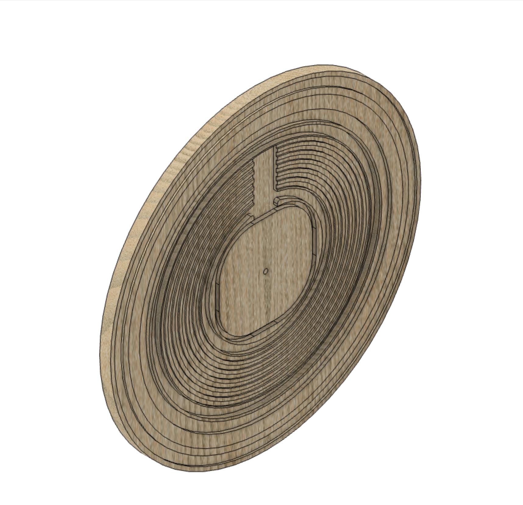
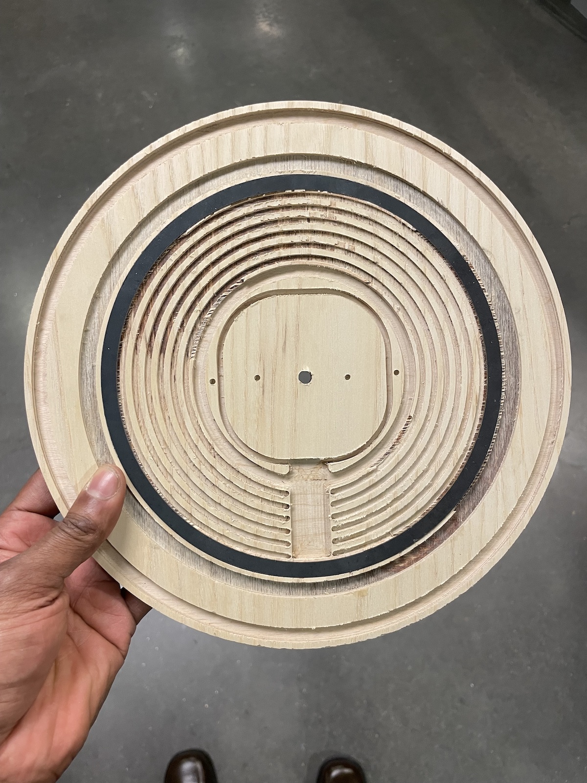
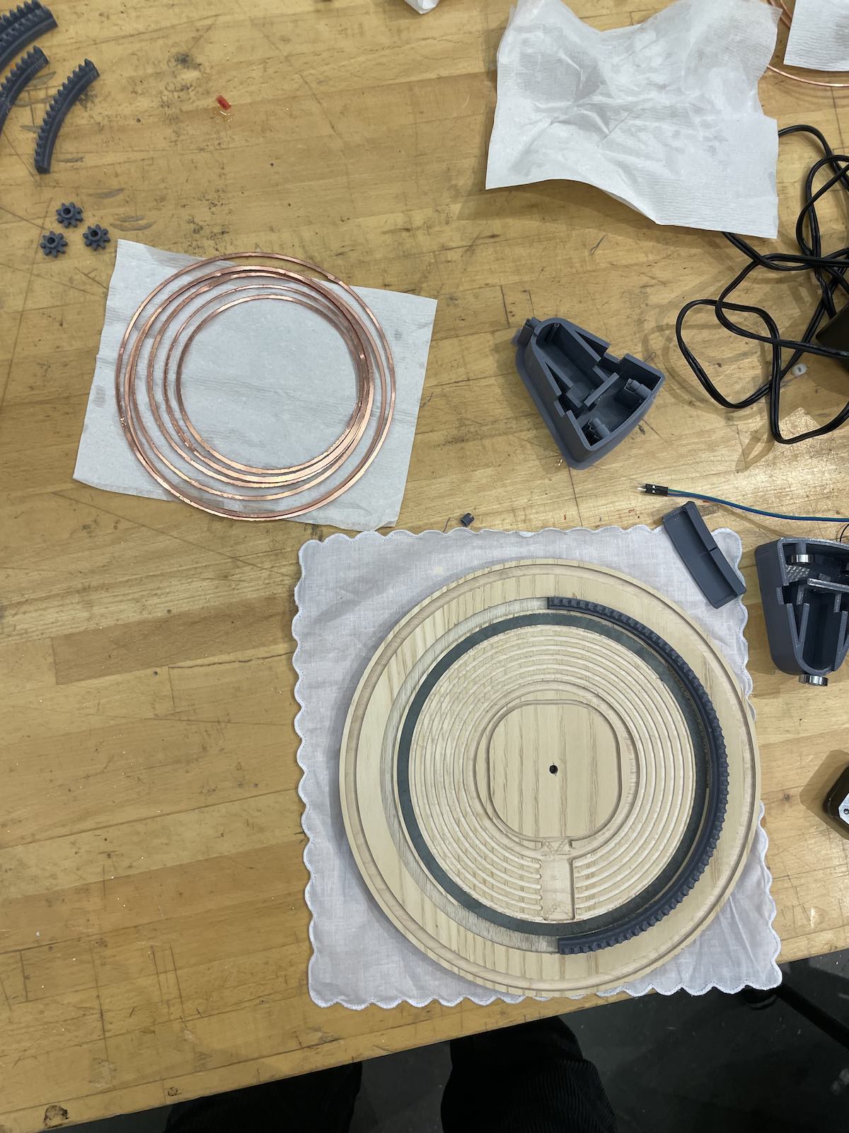
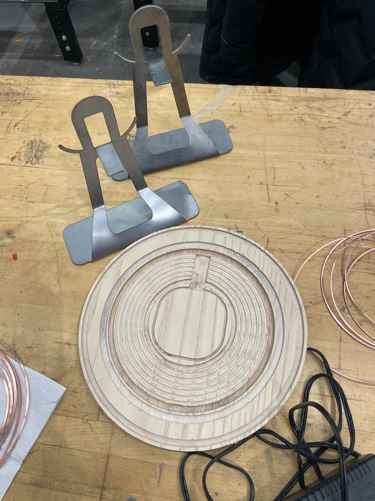
1. The face of the clock is white ash plywood that is thick enough to allow the
clock components to be press-fit into grooves on the back of the face.
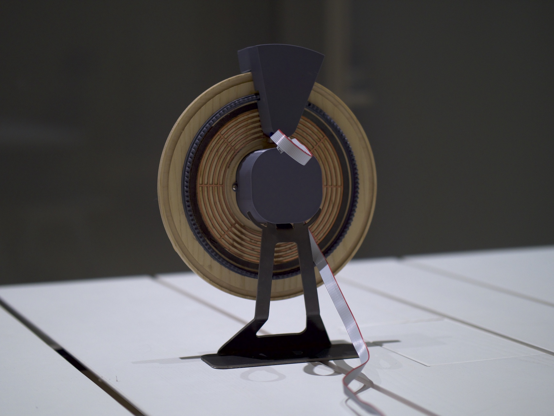
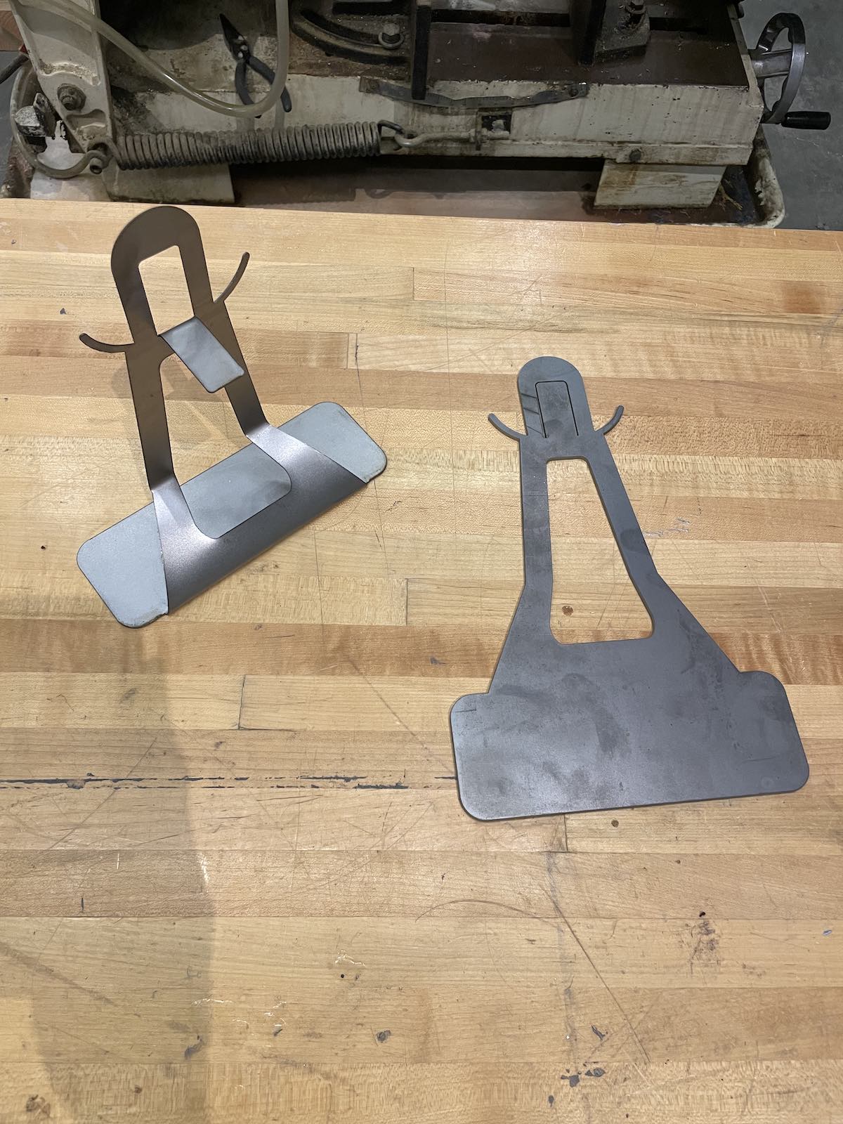
2. The clock stand was designed from a single sheet of steel that was bent to accomodate the structure of the clock
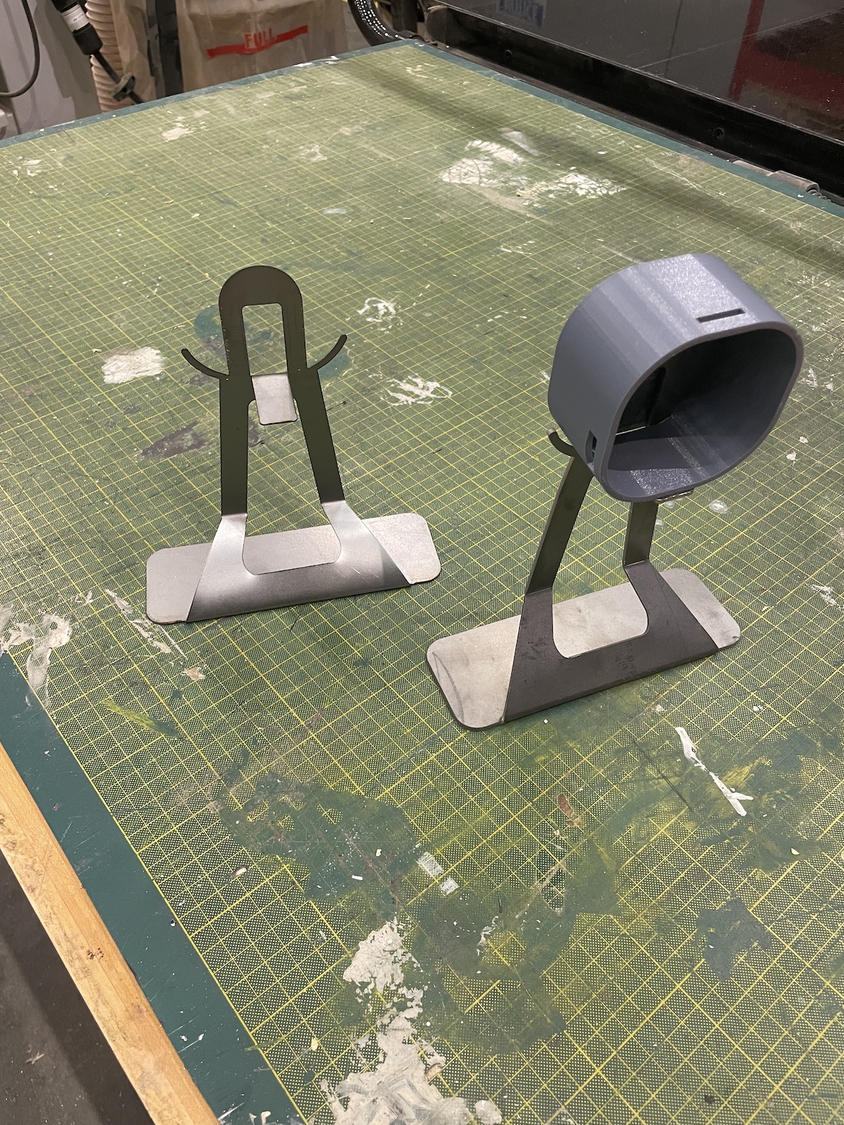
3. The motor and electronics housing components were 3D printed.
4. Copper and Steel rings were embedded in the back of the clock face to satisfy the magnetic and conductive needs of the light source.
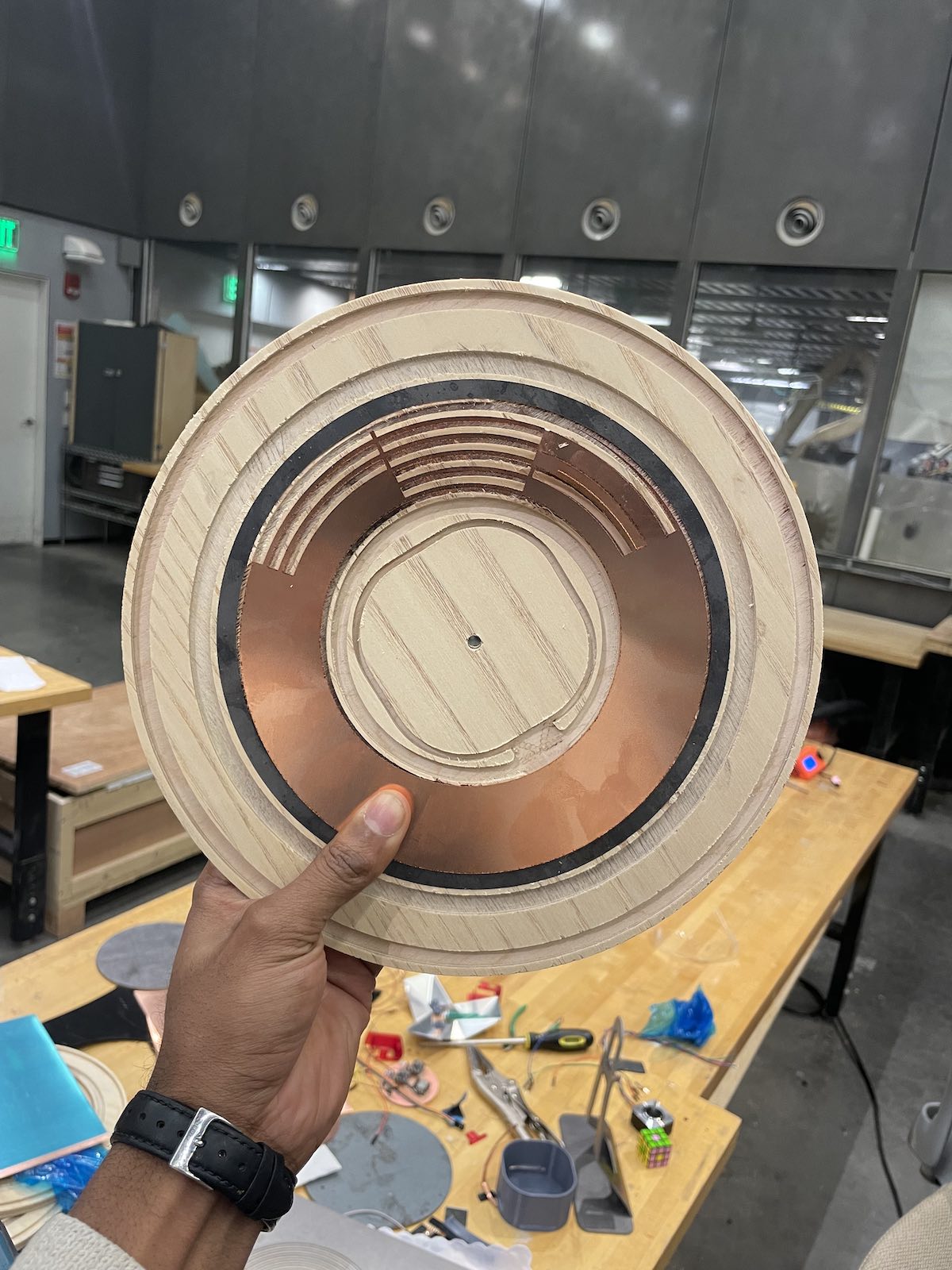
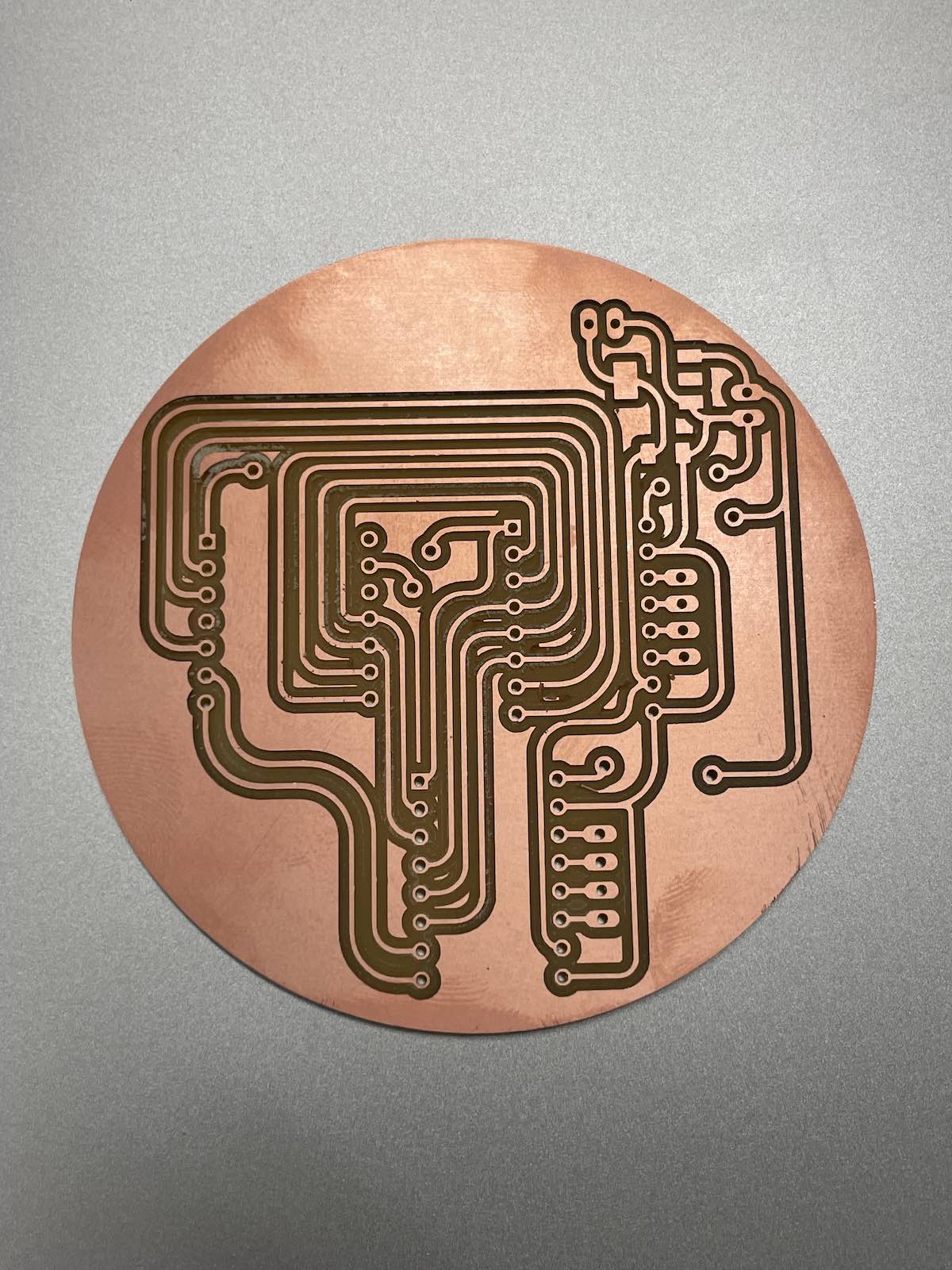
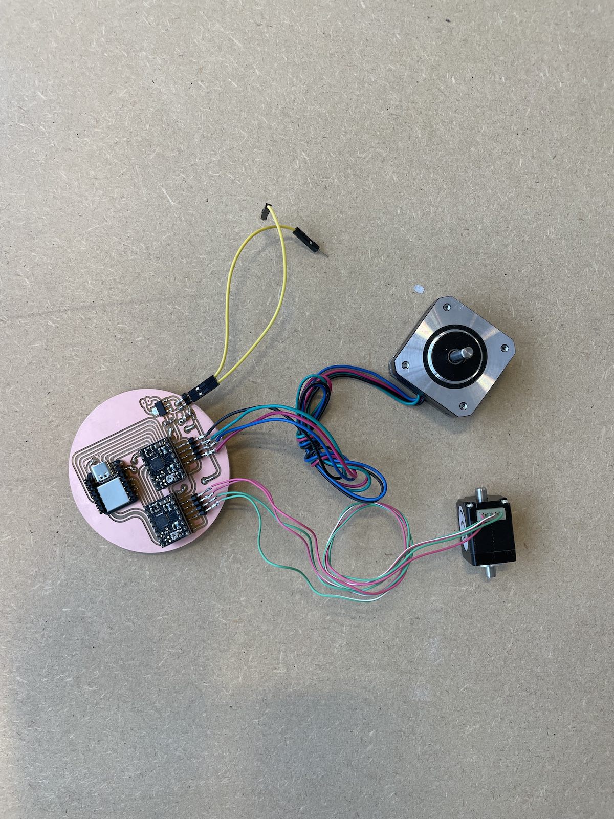
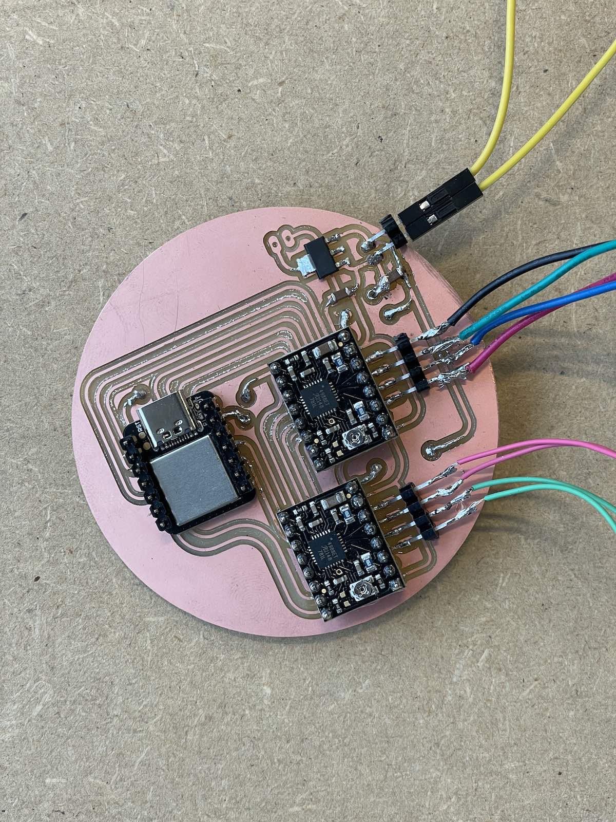
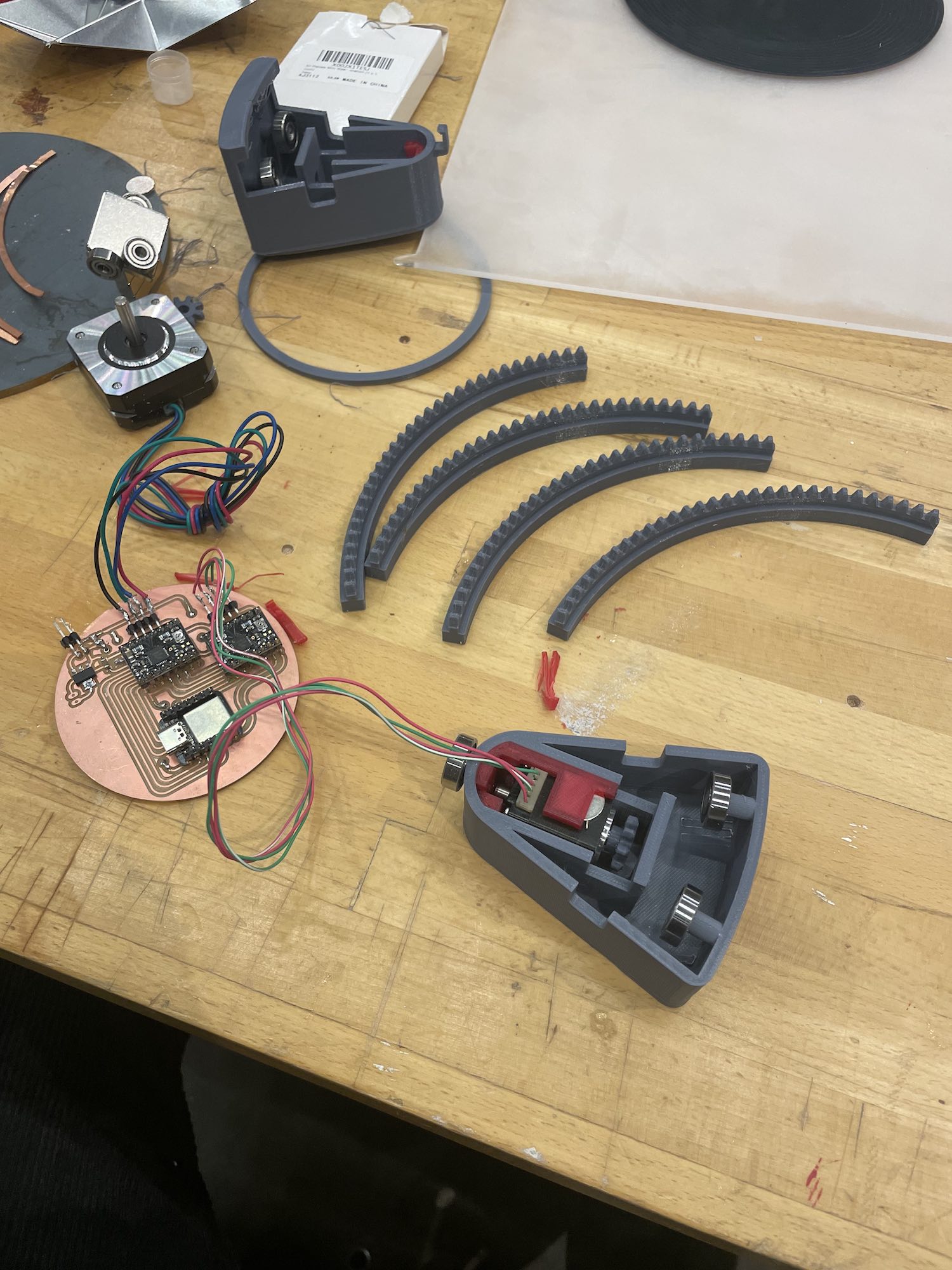
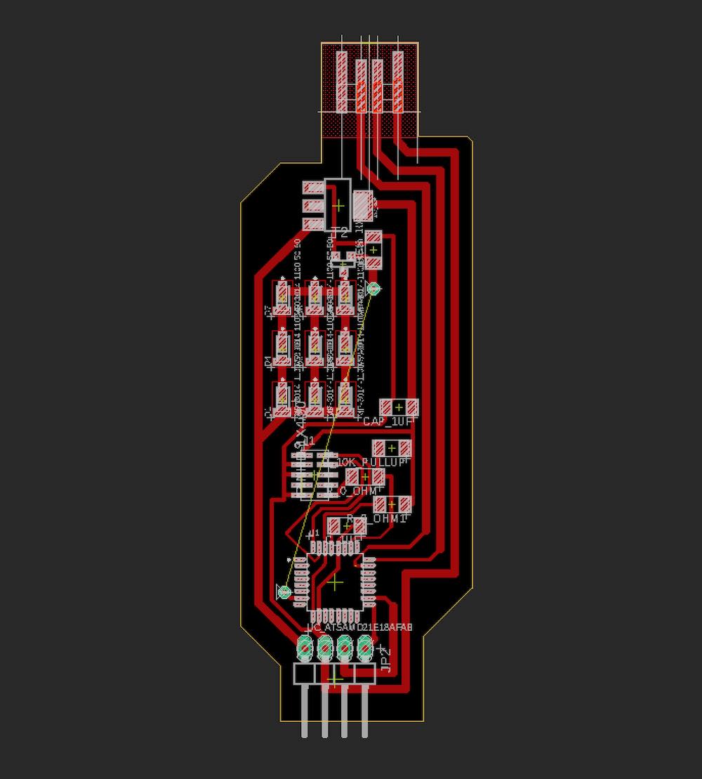
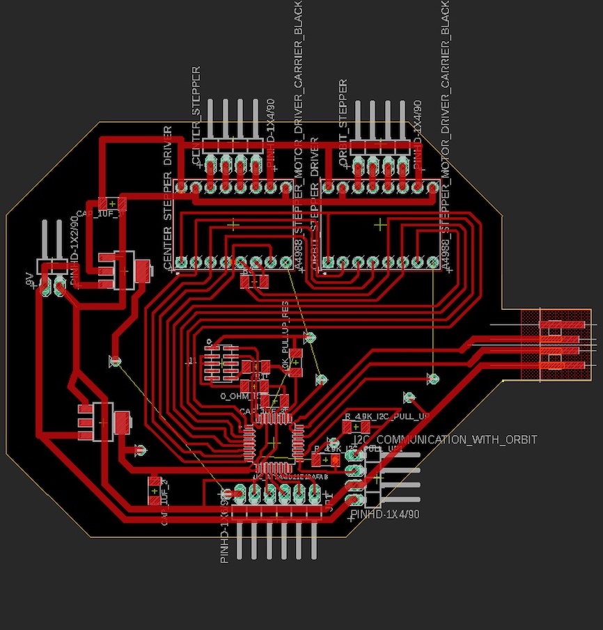
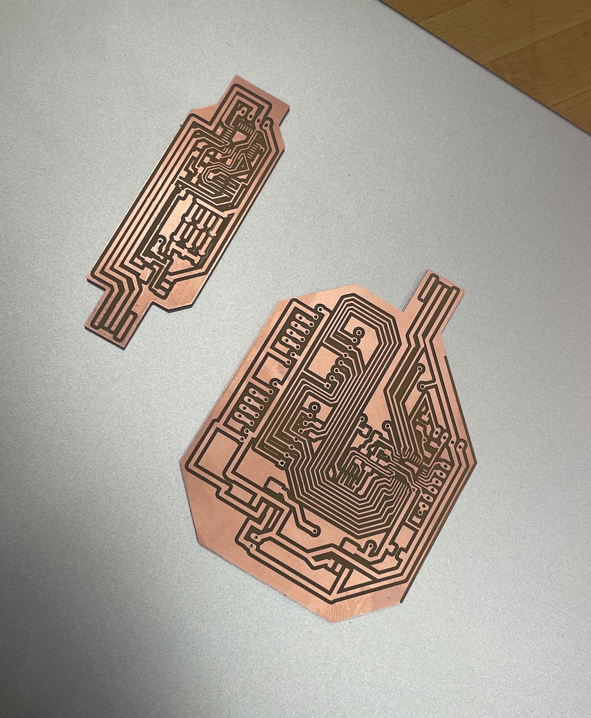
The components were picked and meticulously designed around. The PCB was milled and solderred by hand.
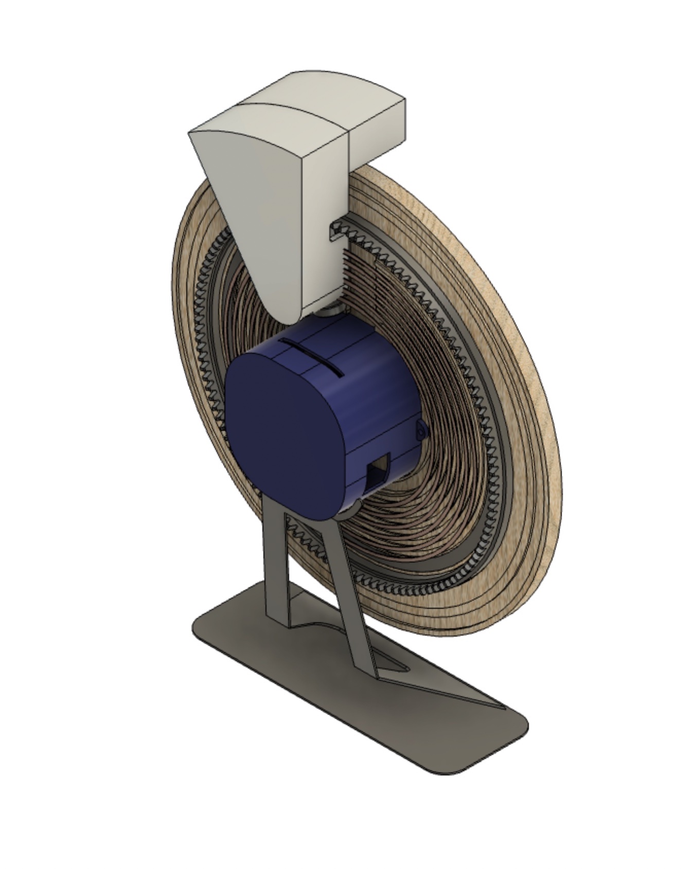
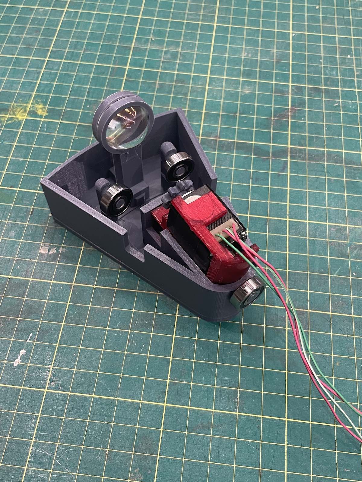
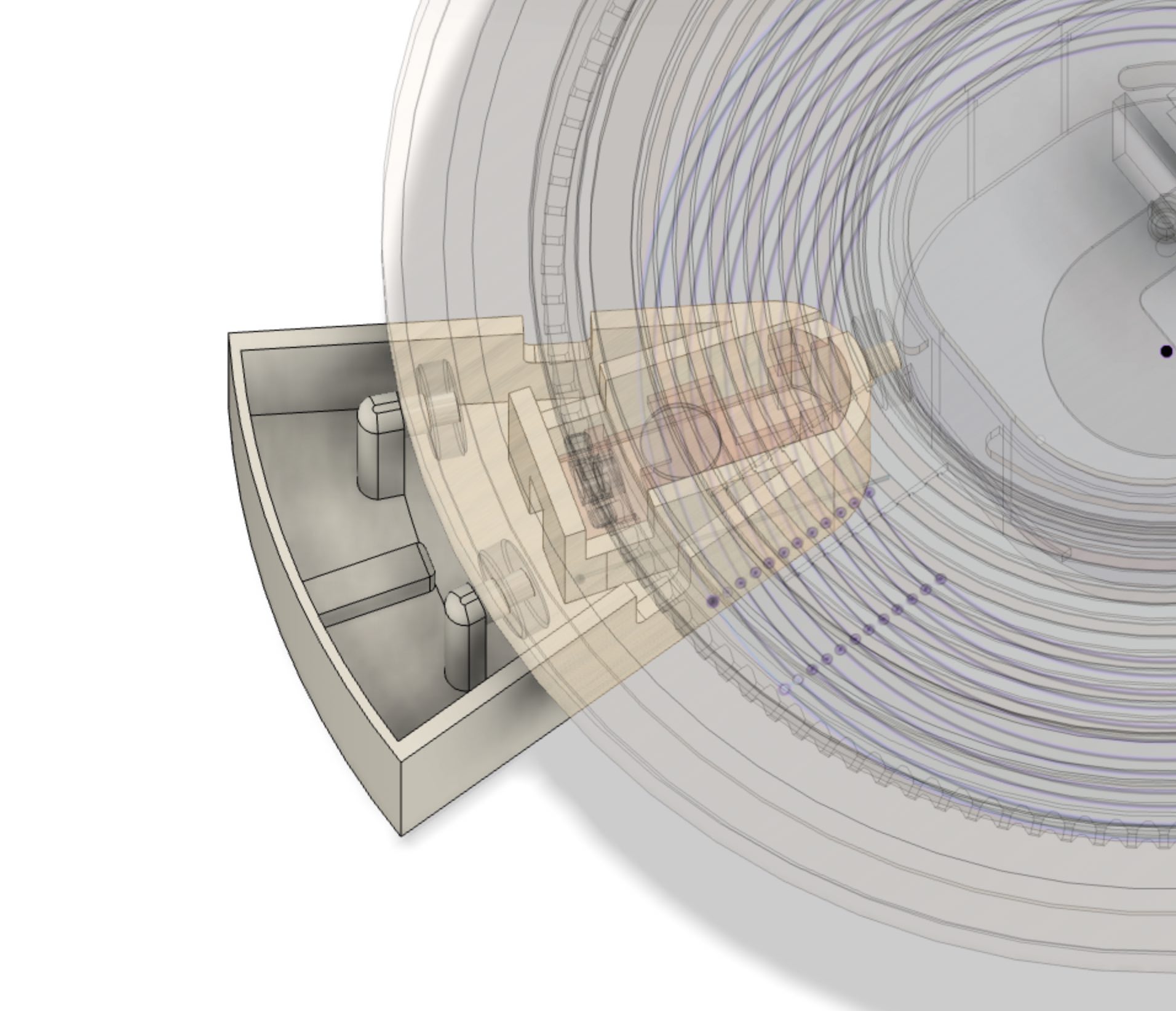
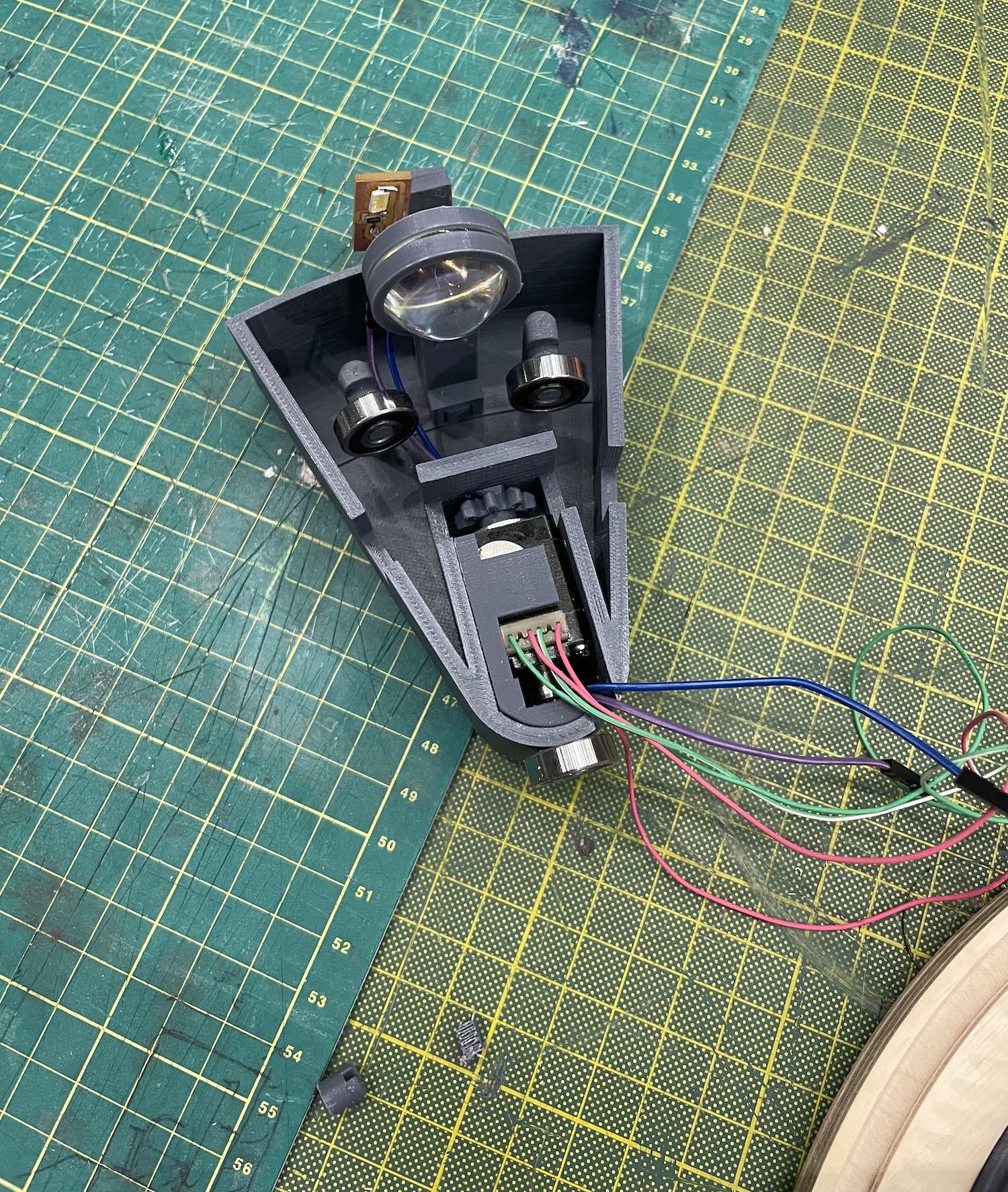
The light source orbits around the face of the clock using a small stepper motor moves across a circular rack and pinion on the back of the clock face. The housing around the light source contains three triangularly placed bearings that sit in grooves on the backside of the clock face to enforce a radial contraint. The housing around the light source also contains a a magnet that holds the housing to the back of the clock face.
Process
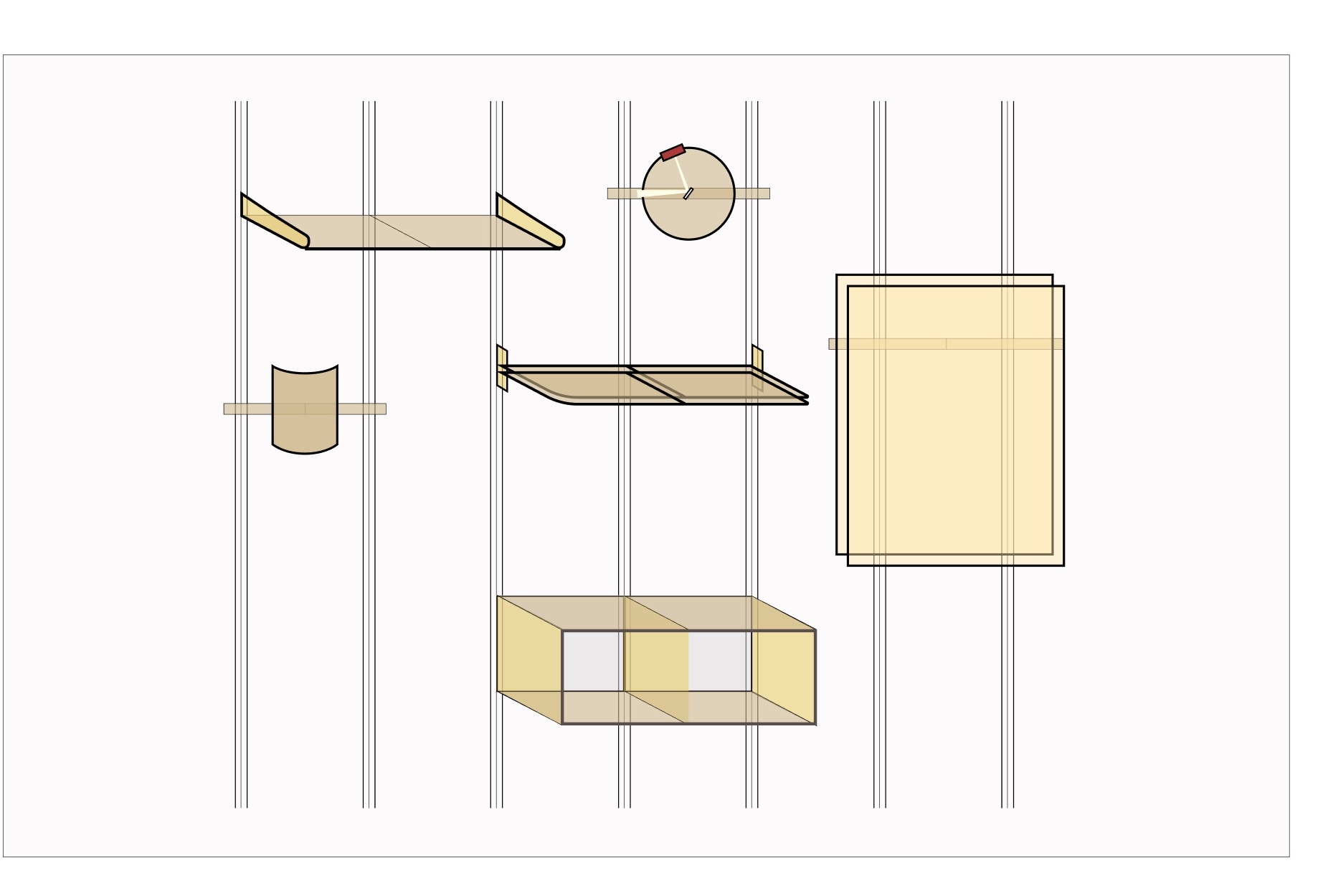
(Initial Idea) Configurable wall system
Inspiration
Dieter Rams / Vitsœ - Universal Shelving System ↗
Robert Stadler - Hanging System ↗
Components
-
Book Case
-
Responsive Light Panel
-
Shelf
-
Light Clock
-
Sconce
-
Painting Mount
Focusing on the Light Clock
A stepper-actuated light source orbits on a circular track around a small planar mirror. The hour and minute arms of the clock are incident and reflected beams of light emitted from the source and refracted off of the mirror.
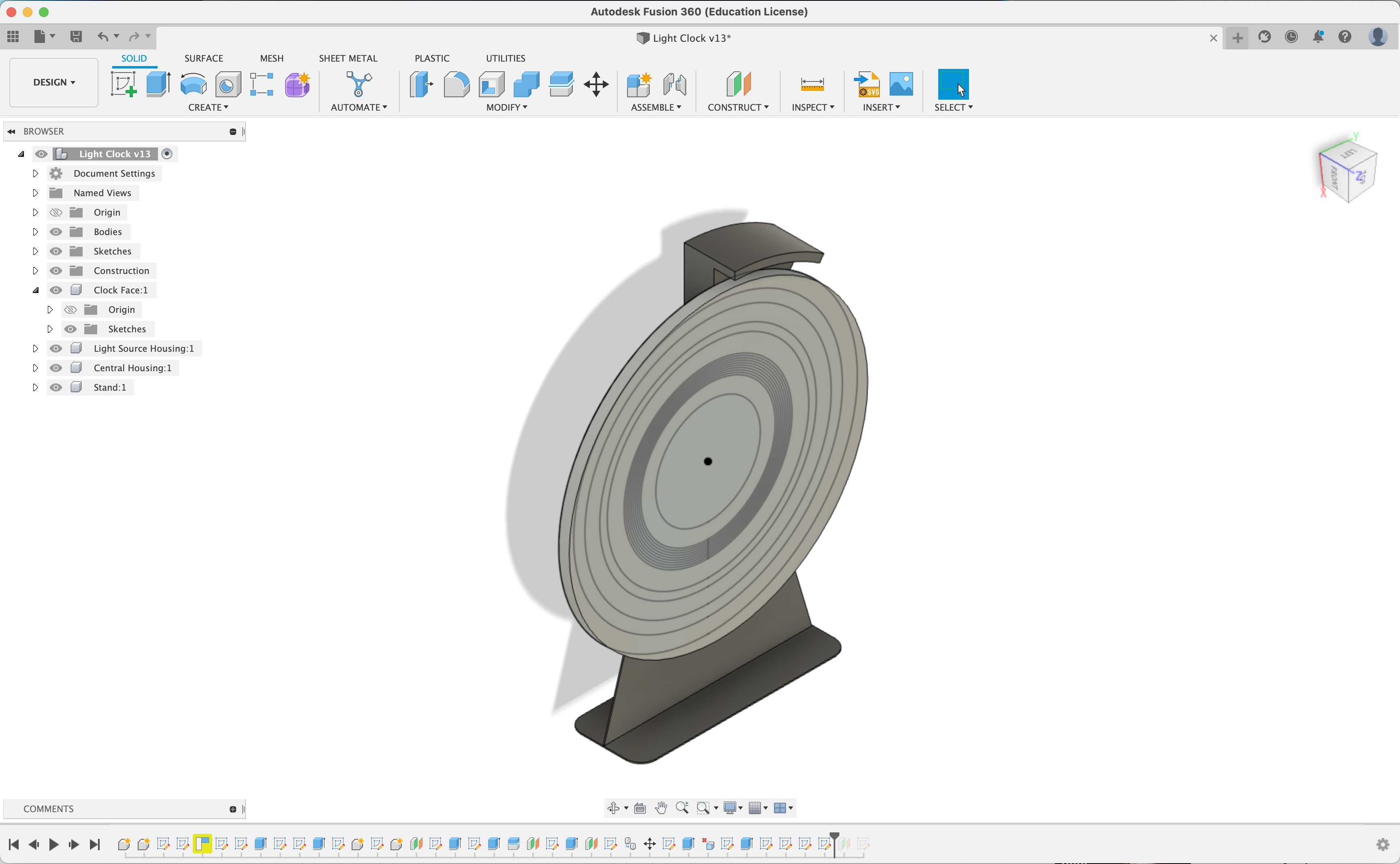
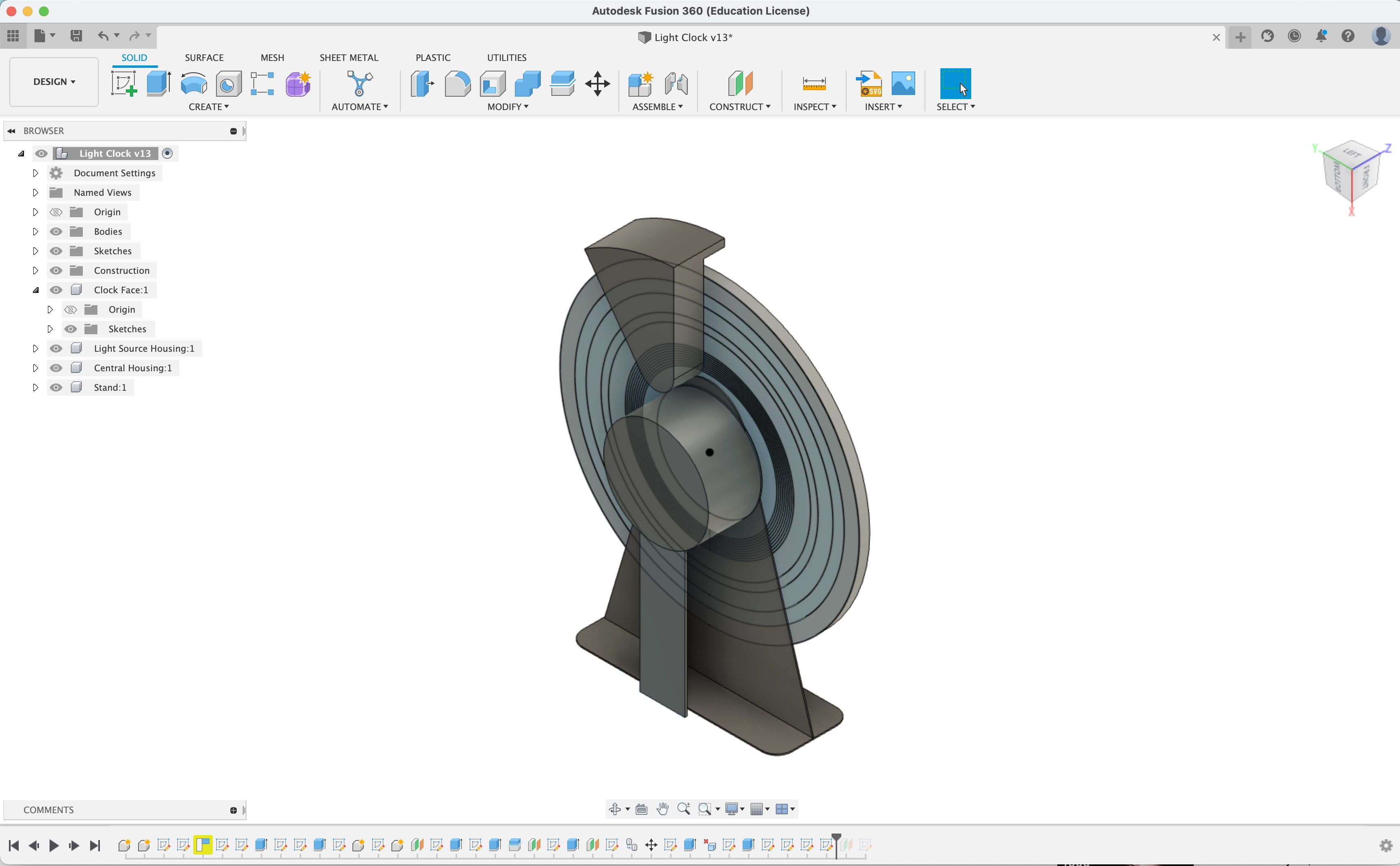
Rough Sketches in Fusion
Software
As much of the design system as possible is automated and parametrized in code. Artistic renderings and animations are creating in OpenFrameworks. Part files are generated in Python & Rhino/Grasshopper. Assembly instructions, product spec sheets, and rendered product images are also auto-generated.
Materials
Light Clock
Purchased Materials:
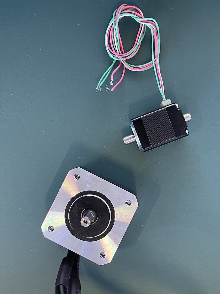
Stepper with magnetic encoder x 2
(in case I want to build it with two magnetic encoders)
Normal 4 wire stepper x 2
(in case I want to take the simplest route forward)
Dual shaft hollow shaft stepper x 1
(in case I want to use this for the mirror at the center)
Pancake stepper without encoder
(in case I want to use this for the mirror at the center)
Warm white LED x 30
DS1342U+T&R Real-time Clock Component
Shelving
Track / Strut Channel
https://www.mcmaster.com/rails/strut-channel-5/construction~solid/
https://www.mcmaster.com/rails/strut-channel-5/
Holes in Track
3/16in
pins designed with 3/16in / #10 diameter
Design
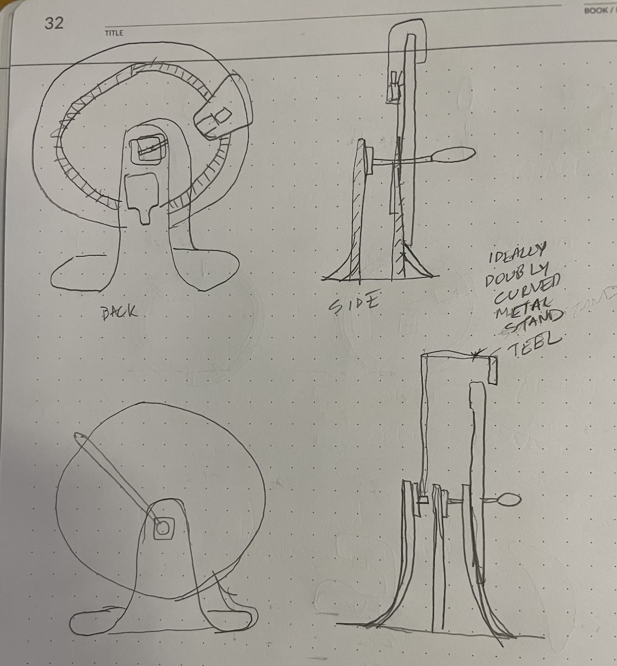
Very Rough Sketches (Light Clock)
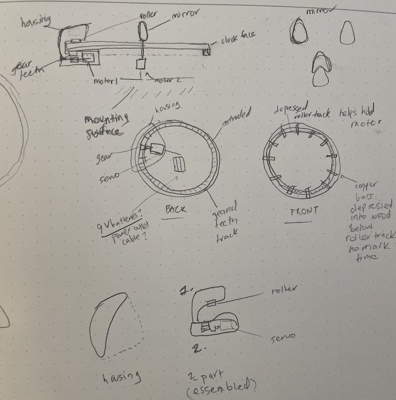
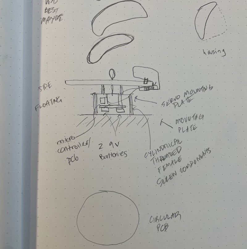
Initial Electronics Design
Electronics & Physical Design Continued..
Completion Timeline
Week of 11/21:
• Complete electronics design
• Complete majority of electronics manufacturing
• Complete initial embedded programming
Week of 11/28:
• Complete CAD drawings and design
• Order non-electronic materials for design
Week of 12/05:
• Begin assembly and design iterating
Week of 12/12:
• Finalize design and begin manufacturing and assembling final design
Week of 12/20:
• Present final design