As of now, my raster only includes rails and shelves made of steel sheet metal.
I'm creative coder and computational designer and a first-year Master's student in the Future Sketches ↗ group at the Media Lab.
.
.
.
I'm interested in modular and procedural design tools and systems ↗. Recently I've been interested in furniture & home objects... For my final project, I hope to build a modular wall system comprised of various components that sense and respond to their surrounding environment.
The wall system will be comprised of modules that serve either a functional or aesthetic purpose,
many of which will have sensory components.
The modular components might include:
shelving / storage
lighting fixtures
audio devices
mounting surfaces
"kinetic decor"
The embedded electronic components might include:
ambient light sensors to adjust lighting conditions
servo motors to move components across the system, as well as drive the kinetic decor
embedded ciruit for the speaker and lighting fixtures
Week 00
Week 01
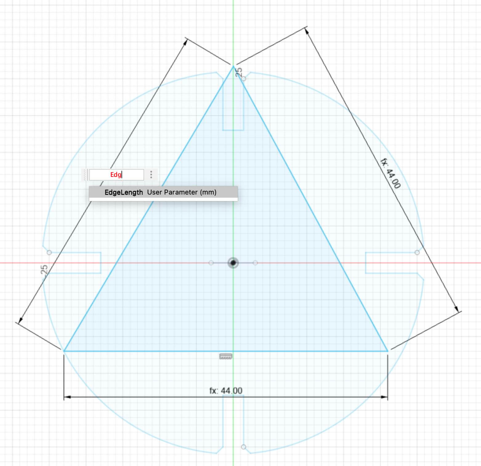
Parametric Construction Kit
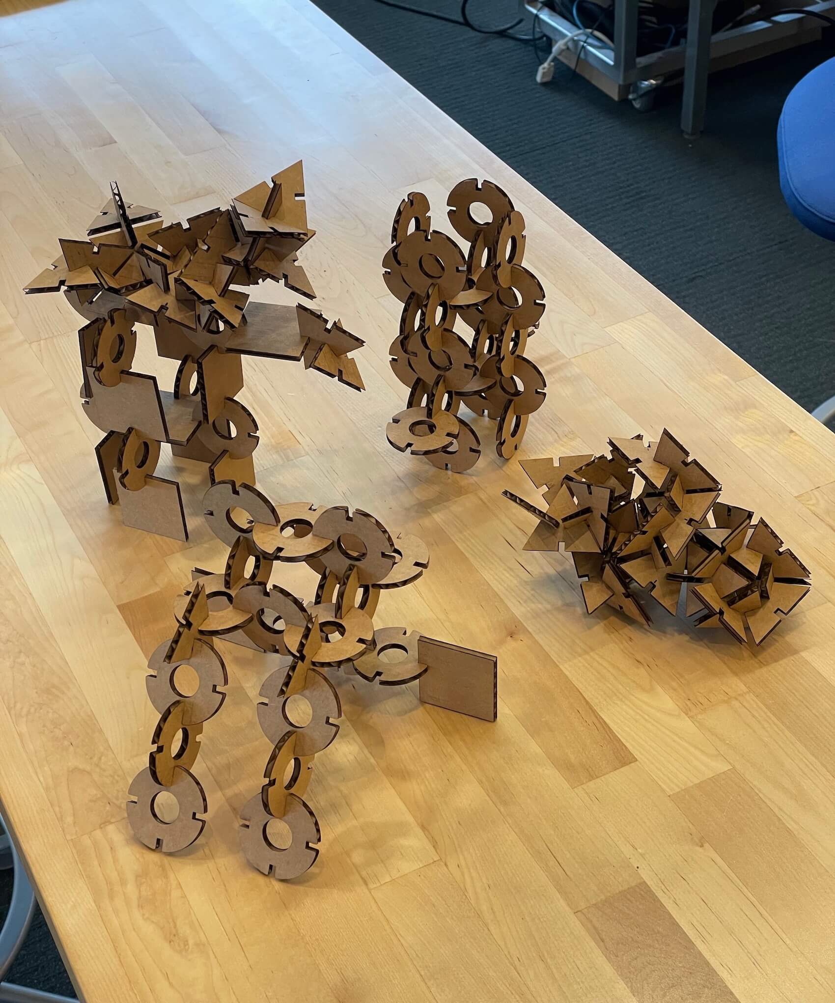
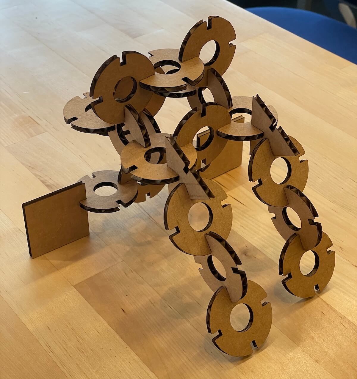
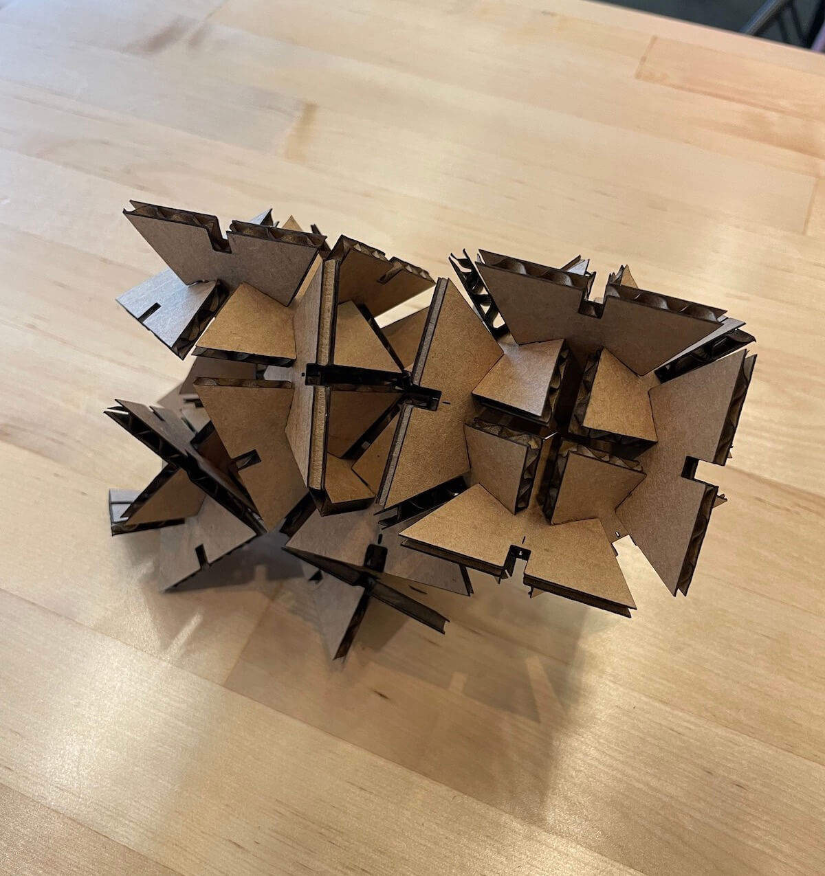
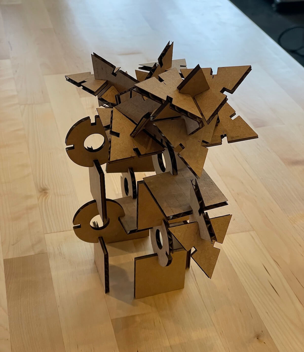
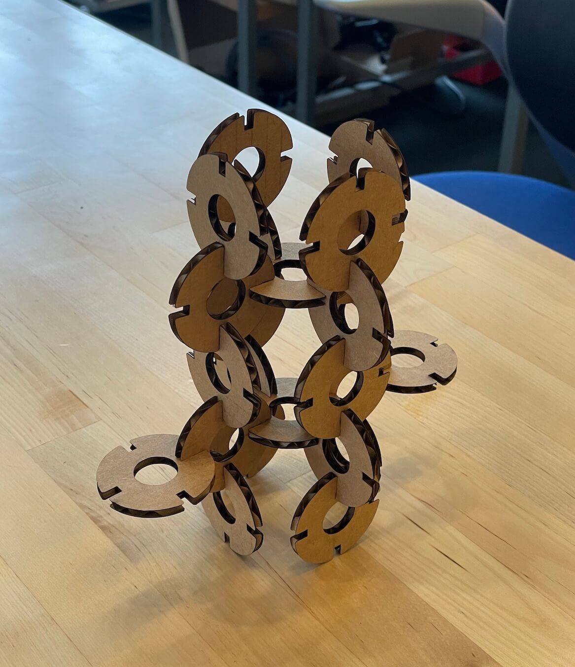
I had experience using a laser cutter before, so this project went relatively smoothly. I cut three different modular parts that could be assembled in various ways to create differents structures.
My initial prototype contained a chamger joint and a snap-fit joint. The chamfer joint worked although I needed to adjust my dimensions for the kerf. The snap-fit joint did not work due to improperly calculating the correct dimensions.
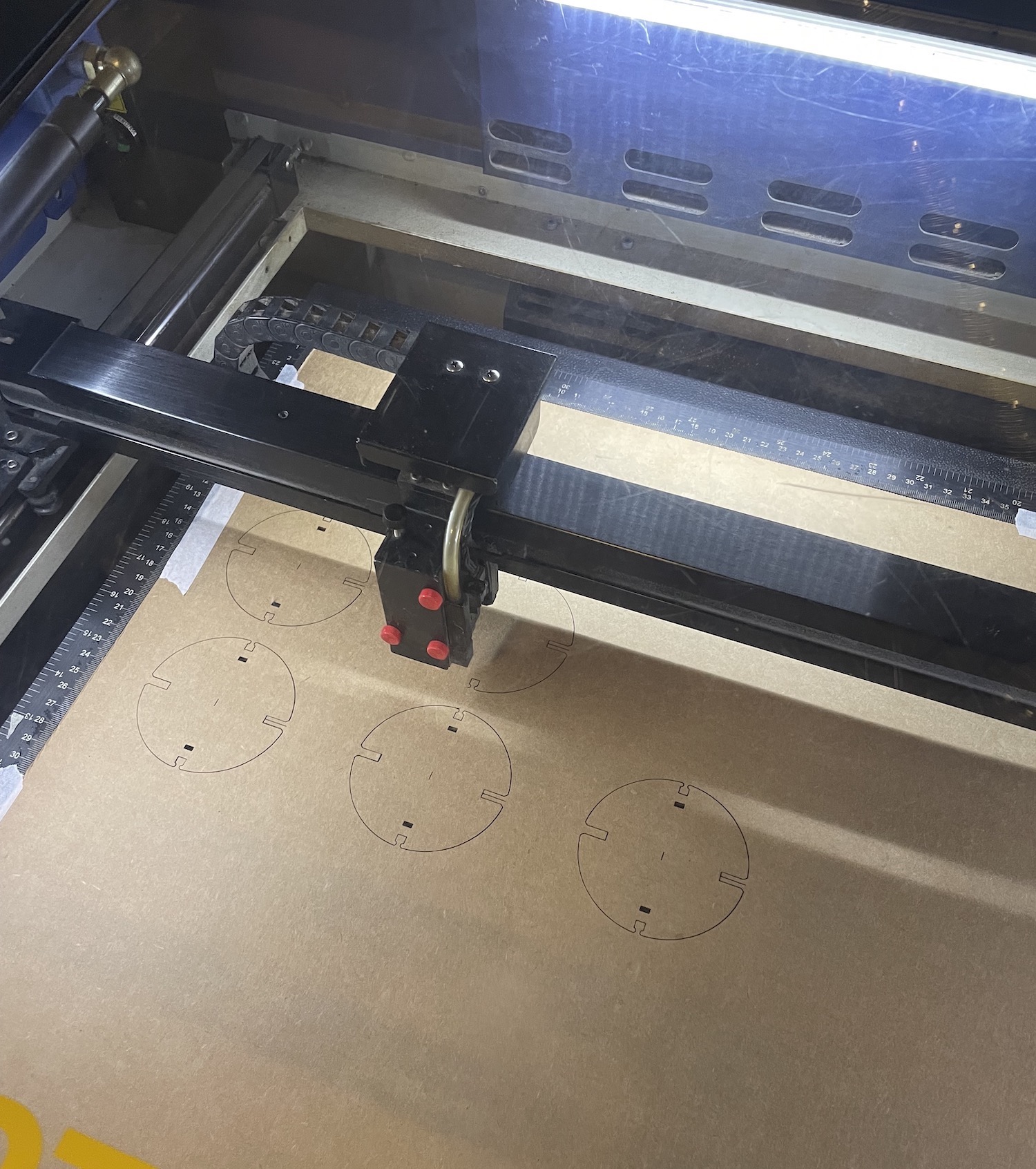
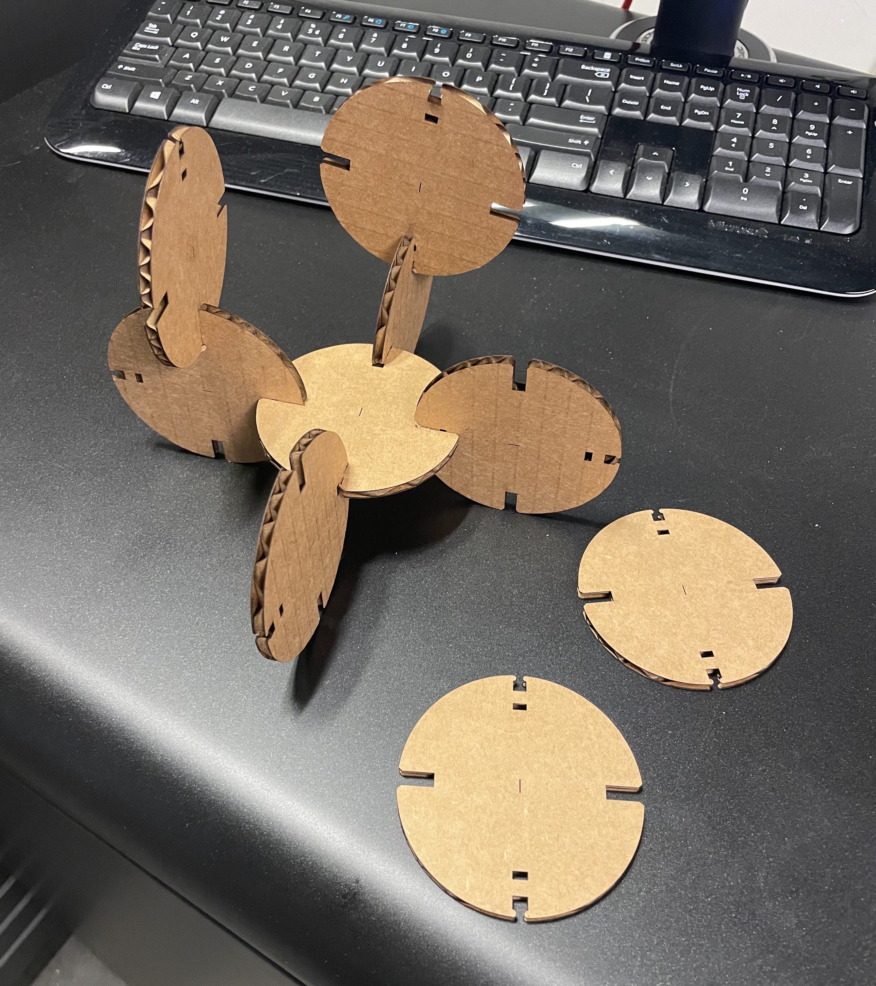
I later went back and fully parametrized the parts to account for the kerf and thickness of the material. Each part also contains small chamfers at the intersecting joints.
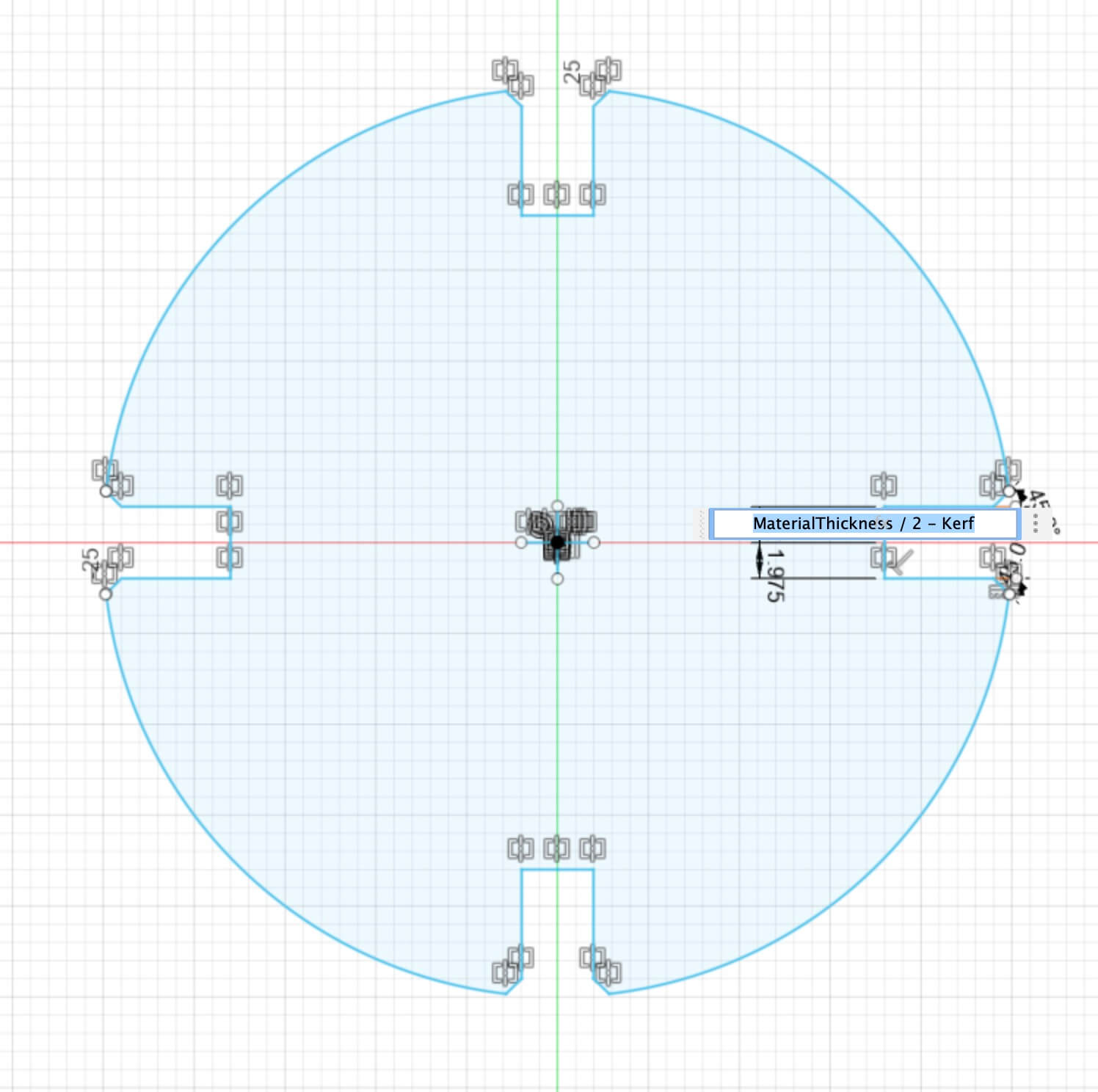
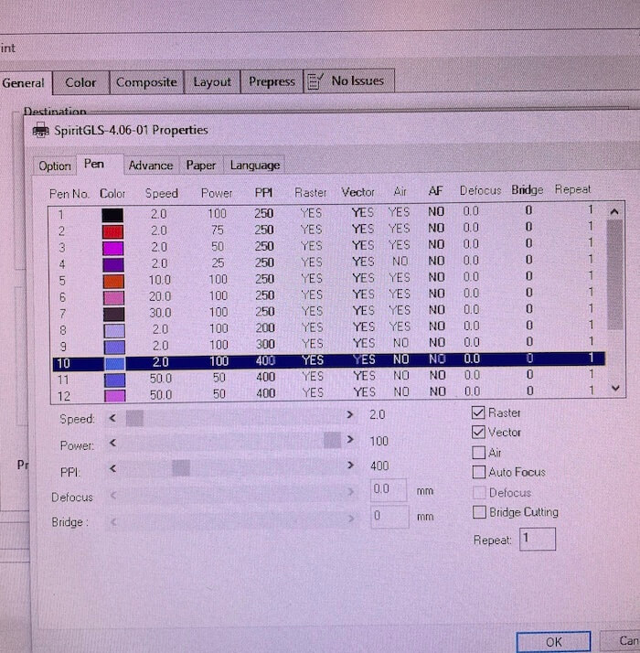
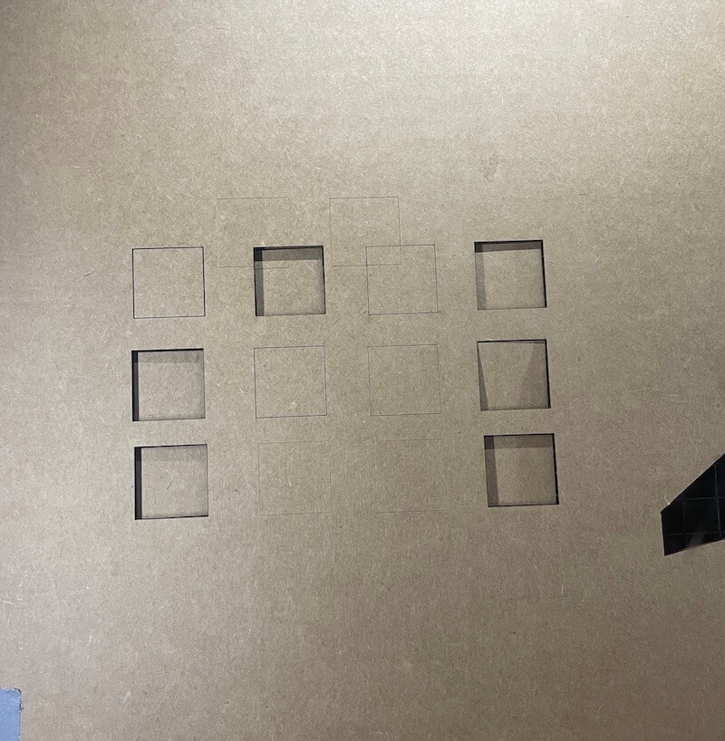
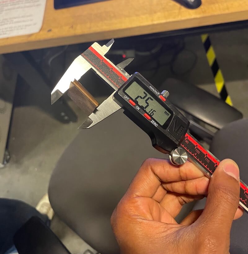
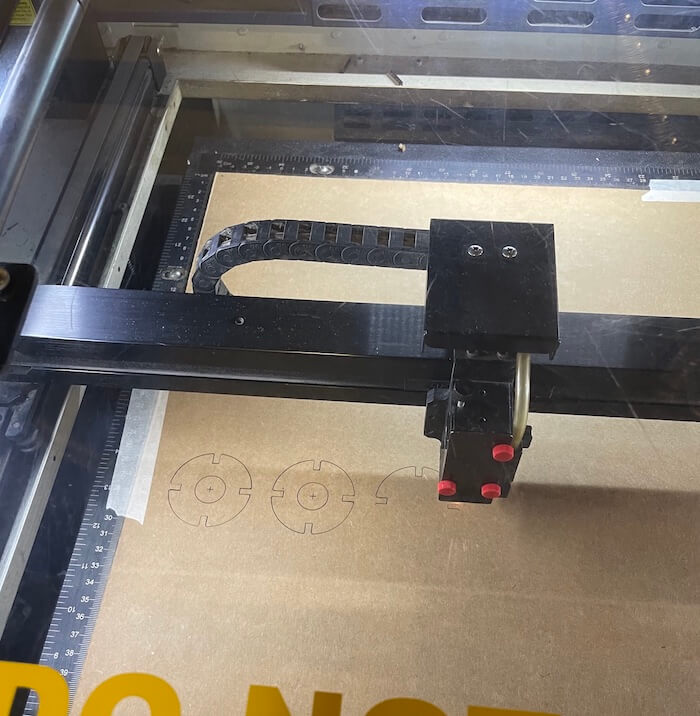
We characterized the laser's power, speed, ppi by cutting 12 squares, varying each value independently, and observing the results of the cut. We measured the laser's kerf by averaging the differences between the real and digital size of the squares.
Vinyl Cutter Exercise
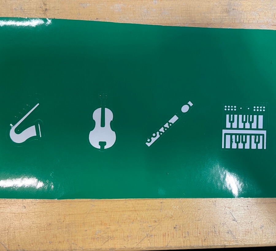
I cut a set of musical instruments using the vinyl cutter.

Week 02
In-circuit Programmer
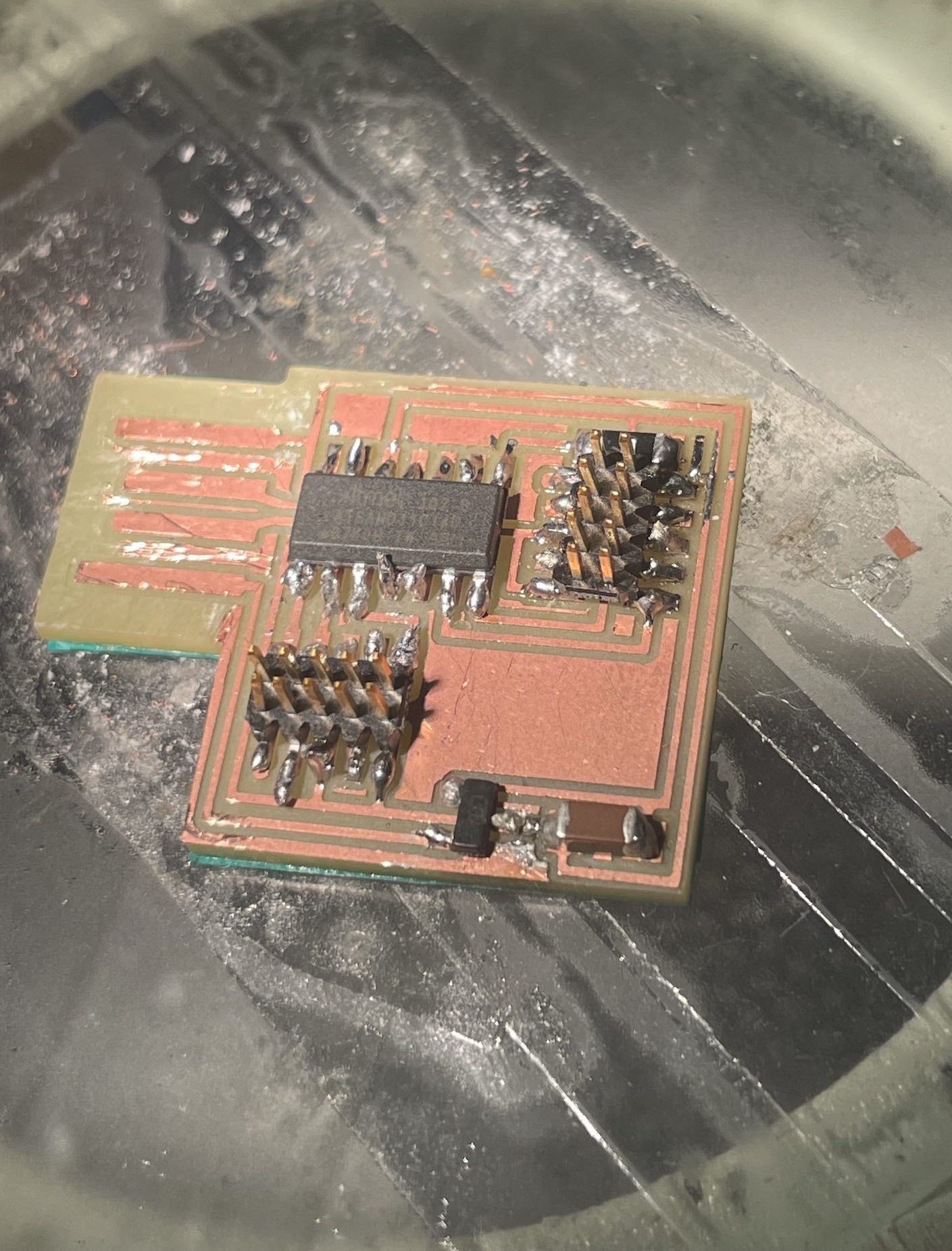
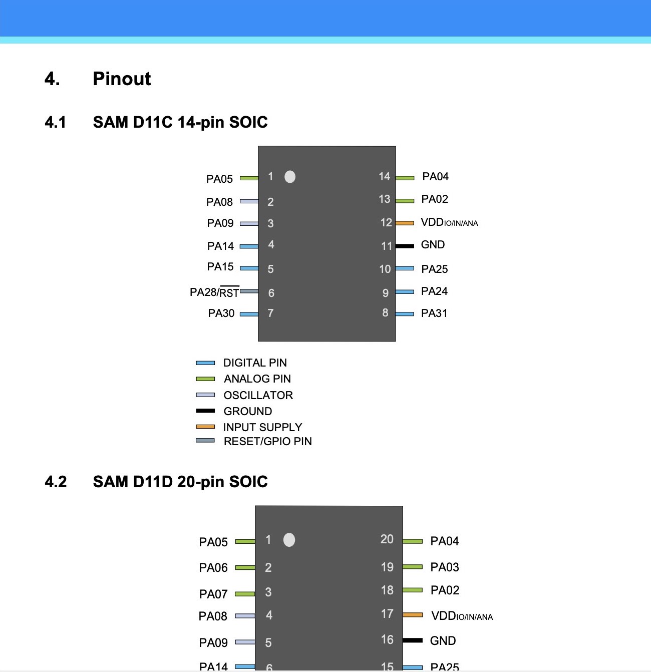
Creating an incircuit programmer was challenging. After much trial and error at every step of the process (visible in the highly unaesthetic resultant hardware), I was able to successfully load the samd11 software onto my microcontroller.
I had no prior expeirence milling PCBs and very minimal experience soldering in the past. The milling process was riddled with mistakes including cutting on a board that was not perfectly planar and accidentally cutting outlines on the file that was intended to be traces.
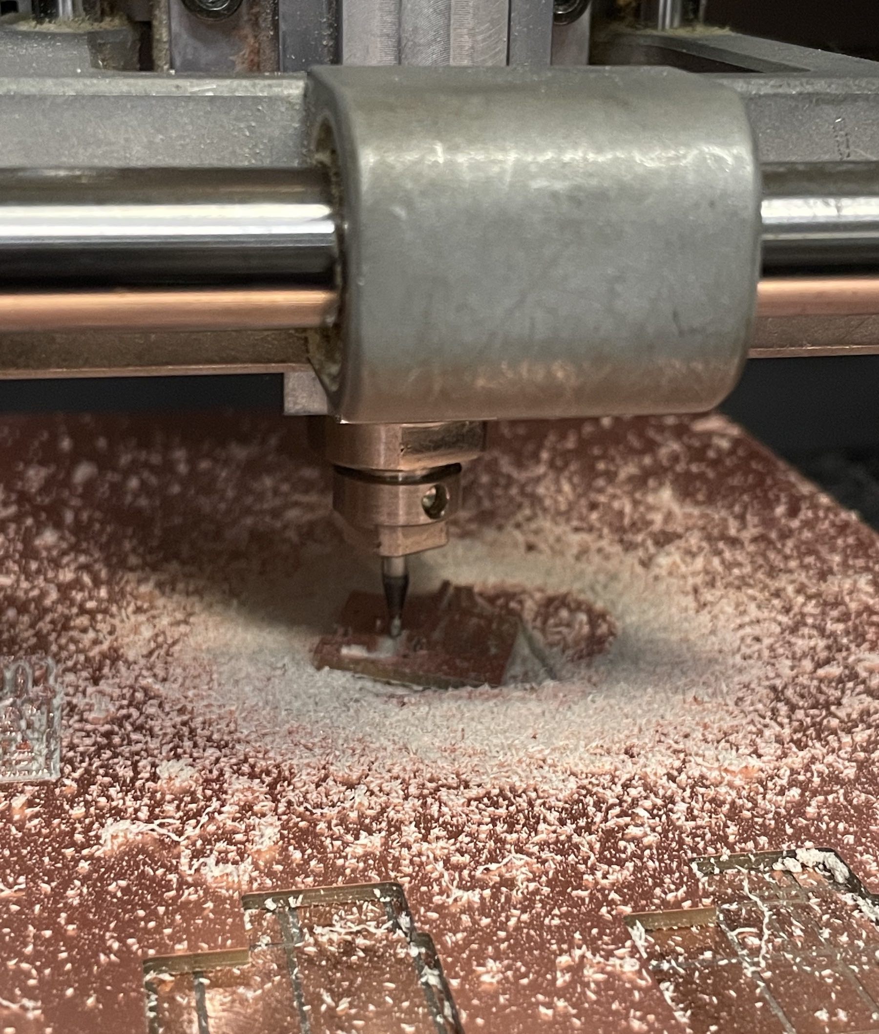
After finally determing the correct order of operations using on both the milling machine and the software, the cutting process went smoothly.
Component Identification
Identifying the correct components was also a learning experience. One critical decision I made was ensuring that I placed the microchip in the correct orientation on the board. I chose the correct orientation by researching similar microchips made by the same manufacturer and observing the product diagrams that indicates the function of each pin. The general orientation of the microchip can be determined by the circle printed at the top left corner of the chip.
Soldering
The soldering process proved even more difficult than milling. After soldering half of the circuit, I had to restart twice due to applying too much solder to the pins on the microcontroller.
My soldering result was quite hideous. I didn't use the flux when I soldered, which likely would have resulted in more uniform connections from the pin to the board. Additionally, the copper on my board did not peel off easily after making an incision in the copper with the exacto knife and attempting to peel the copper back with the tweezers. The boards exterior also turned out quite unsightly.
I did finally complete the soldering process and took care to ensure all of the paths on the circuit were maintained. I then added two layers of electrical tape to the back of the PCB, and scraped off all of the cooper that was feasible around the USB connection paths.
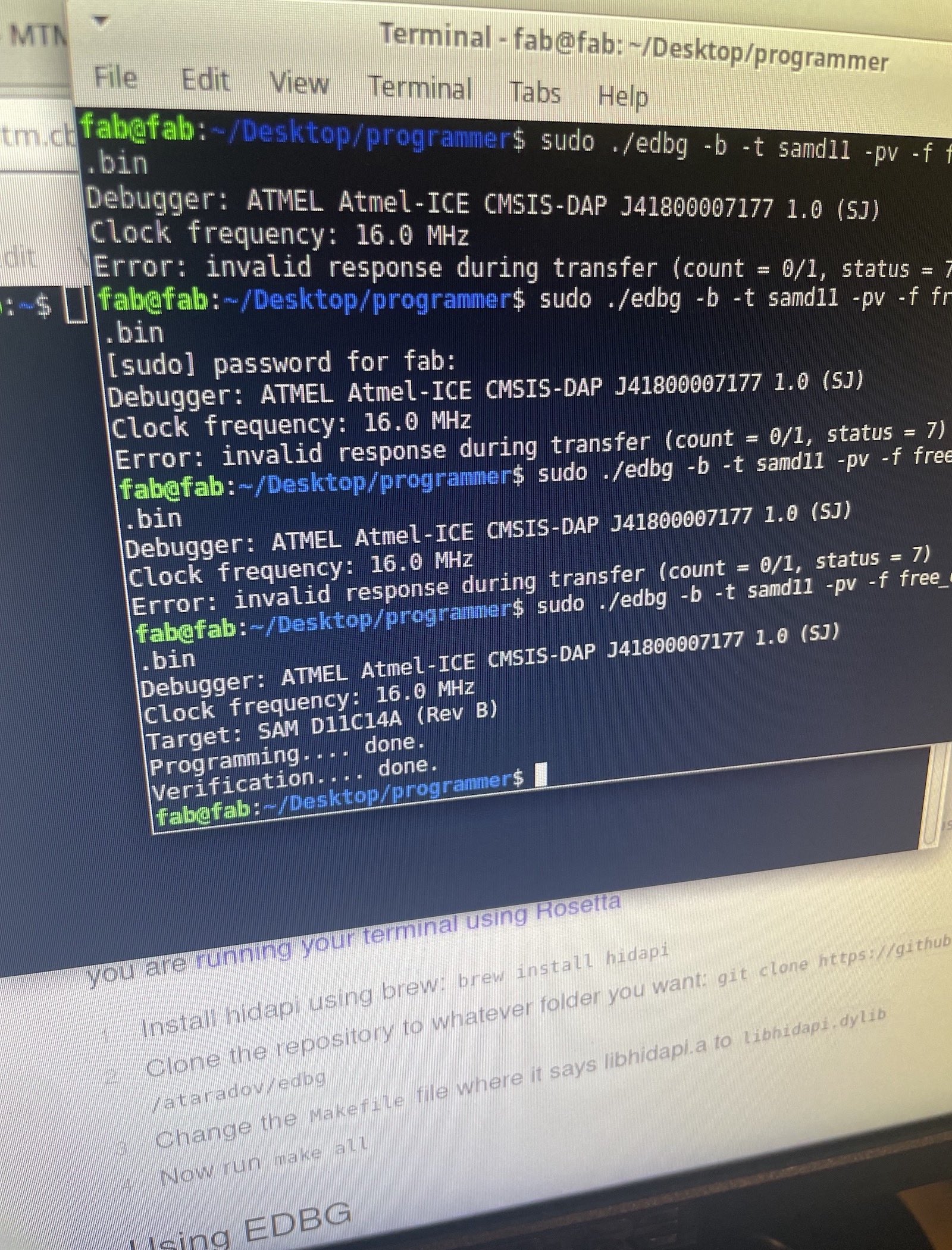
My first attempt at loading the SAMD11 program onto the microchop was unsuccessful. I plugged my circuit directly into the computer and the
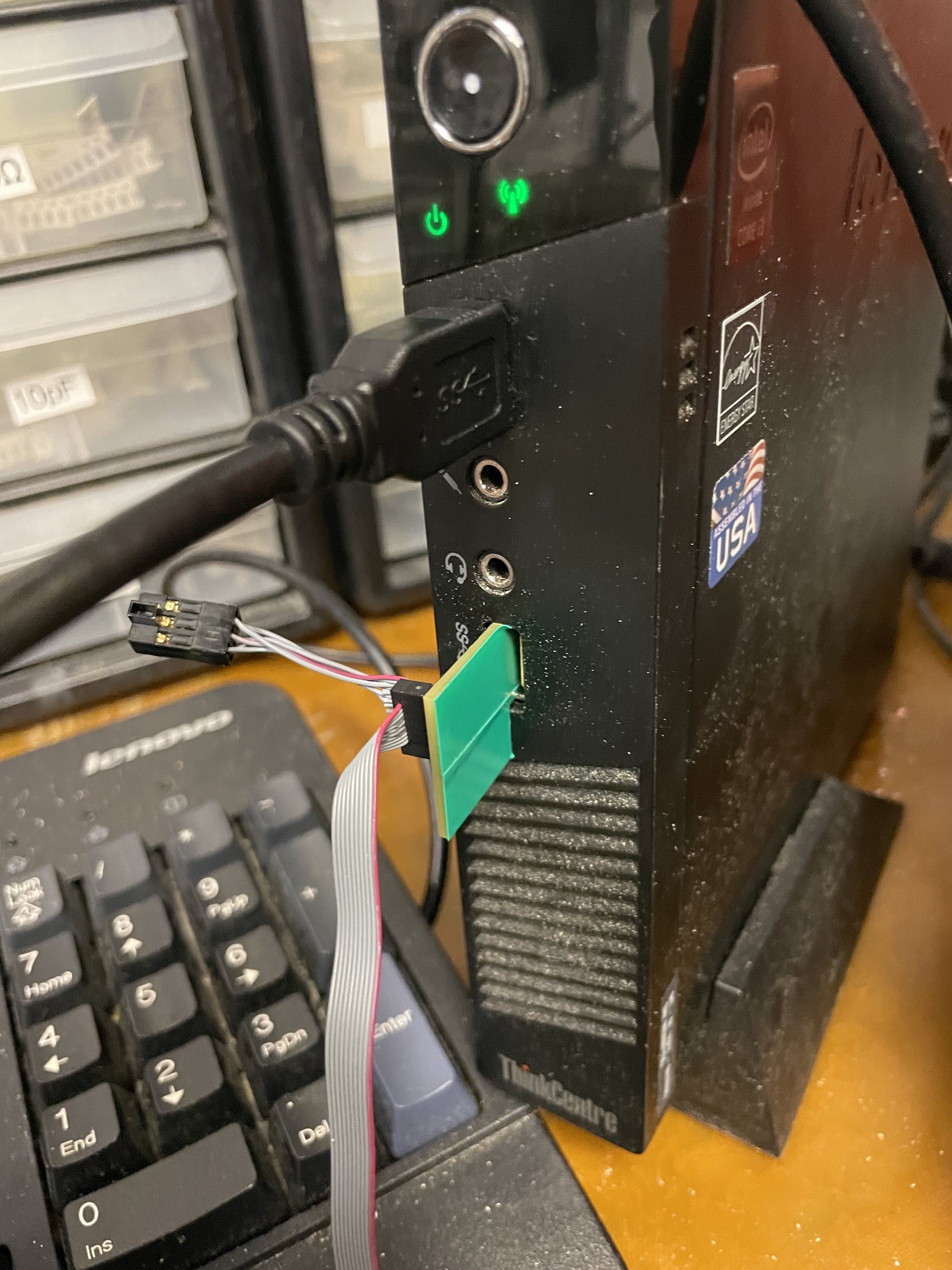
I revisted the lab the next day and used a different computer as well the USB hub. This time the usb hub identified my PCB indicated by the green light on the hub and I was able to successfully load the program onto the microchip.
I verified this via the output displayed in the terminal. Despite the fact that the aesthetics of my final product leave much to be desired, I'm glad that I was able to overcome the technical hurdles involved in programming my first microcontroller.
Week 03
3D Scanning & 3D Printing
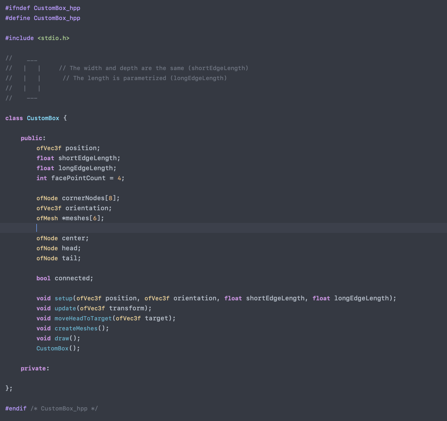
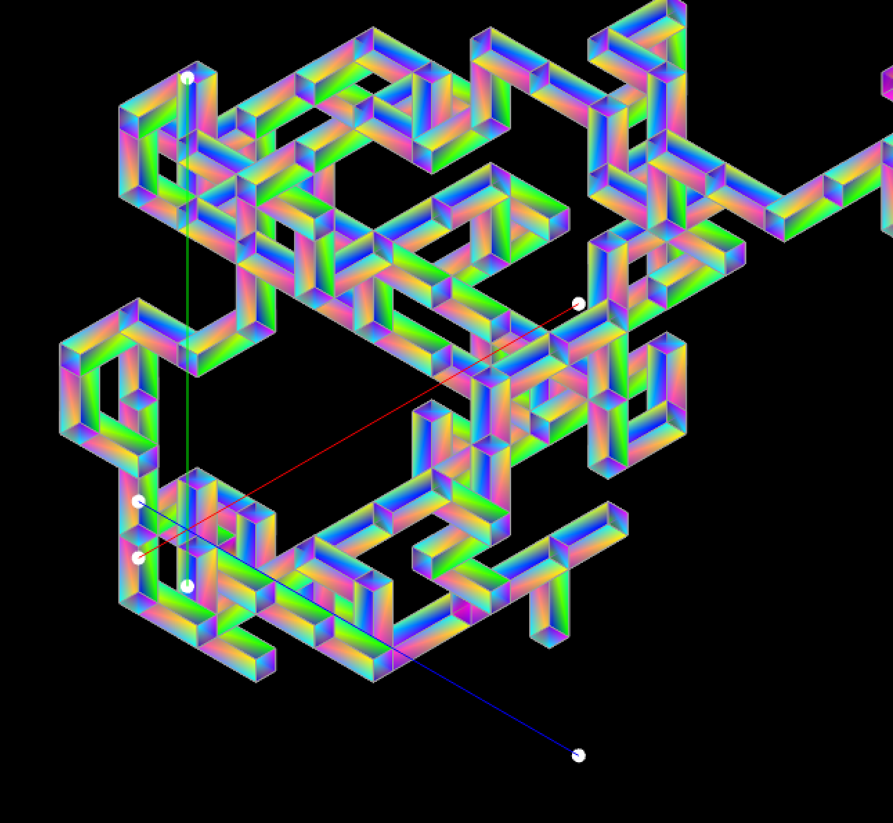
One of my personal goals for the week is to begin learning the creative programming language OpenFrameworks ↗. Specifically, I wanted to get comfortbale programming in 3D using OF. I decided to use this assignment as an opportunity to design a 3D printed object using OF and Rhino. My overall design was limited by time constraints, but I did manage to design a three dimensional object using OF to generate a Python script to run in Rhino.
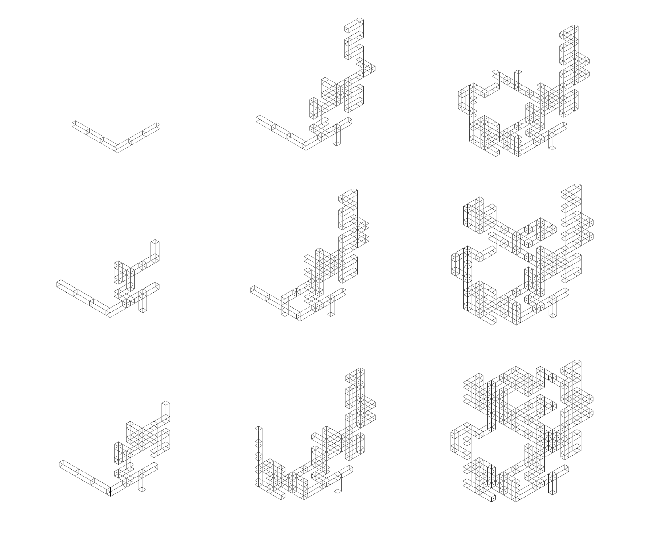
The design is a bounded 3-dimensional semi-random walk of rectangular boxes that are controlled using probabilistic parameters to influence the direction of the walk and placement of the next box.
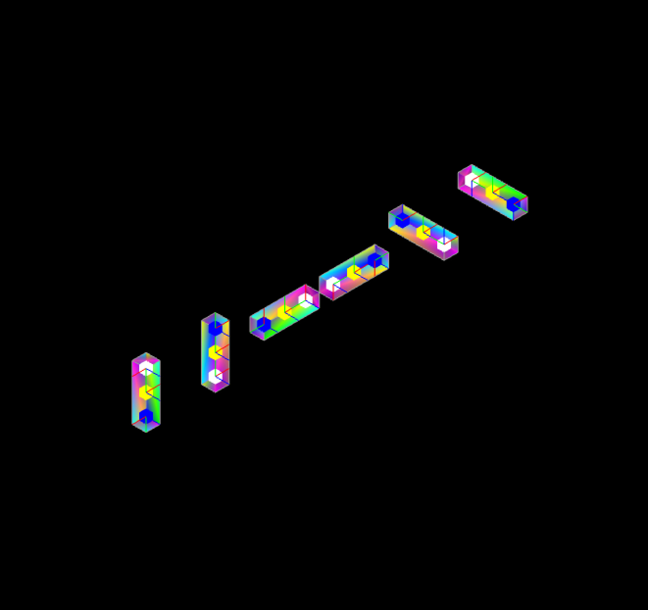
I experimented with some probabilistic branching behaviour, but ultimately decided that a continuous random walk gave the nicest results.
I also automated the creation of 2-dimensional drawings of the structure.
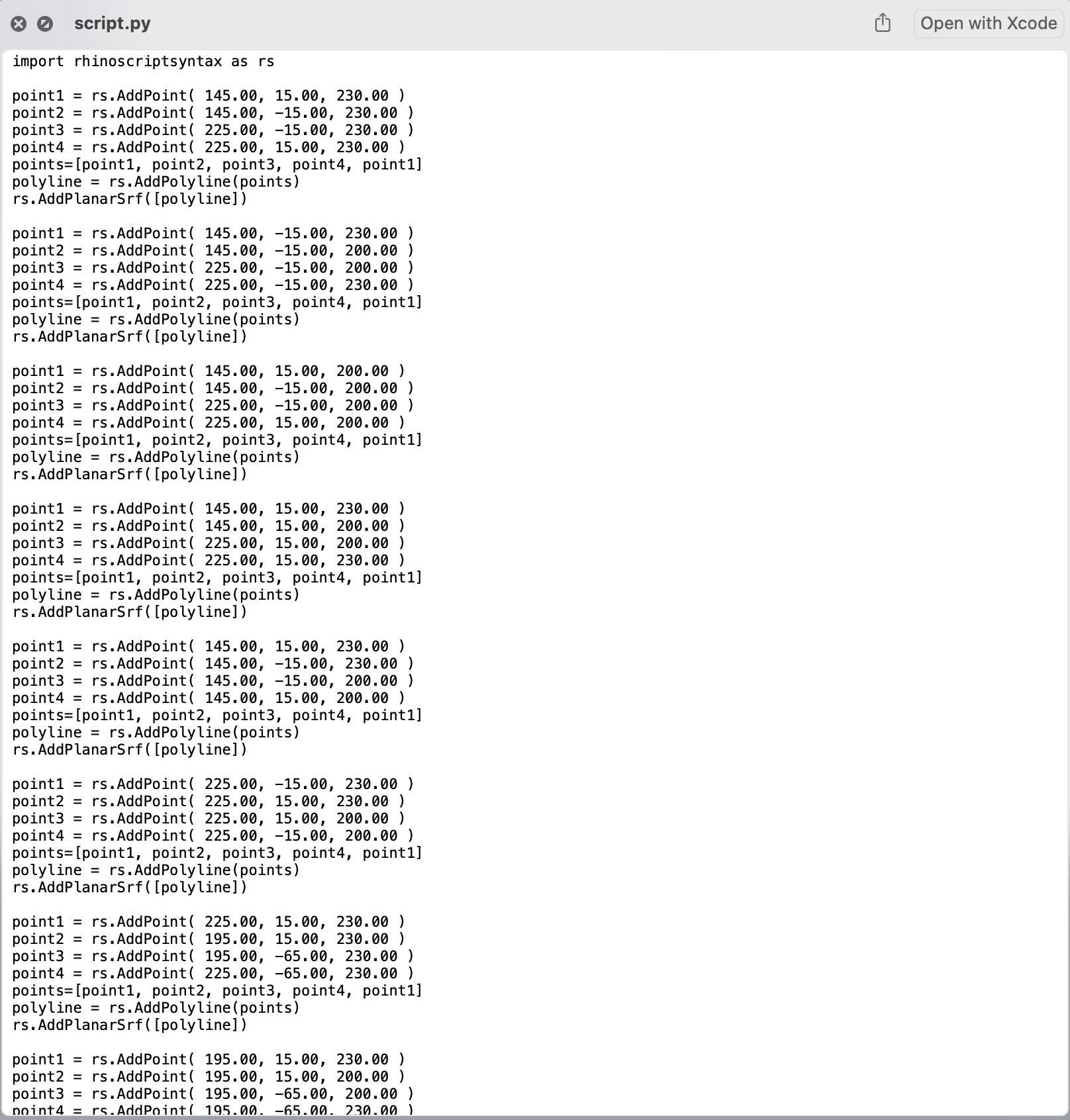
After implementing the design using Open Frameworks, I needed to translate the design into Python and RhinoScript↗ to generate the structure in Rhino. I planned to use the open networking protocol OSC↗ to send python commands via a local network connection into an OSC Listener in Rhino. Unfortunately, opening a live python interpreter in Rhino isn't feasible as I'd assumed. However, Rhino can easily import and run static Python scripts. My short term solution was to use Open Frameworks to write a Python and RhinoScript script that I could then run in Rhino.
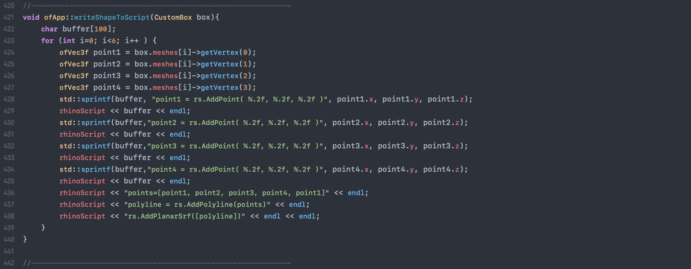
The function in Openframeworks to create the python script ↑. The truncated script ↓.
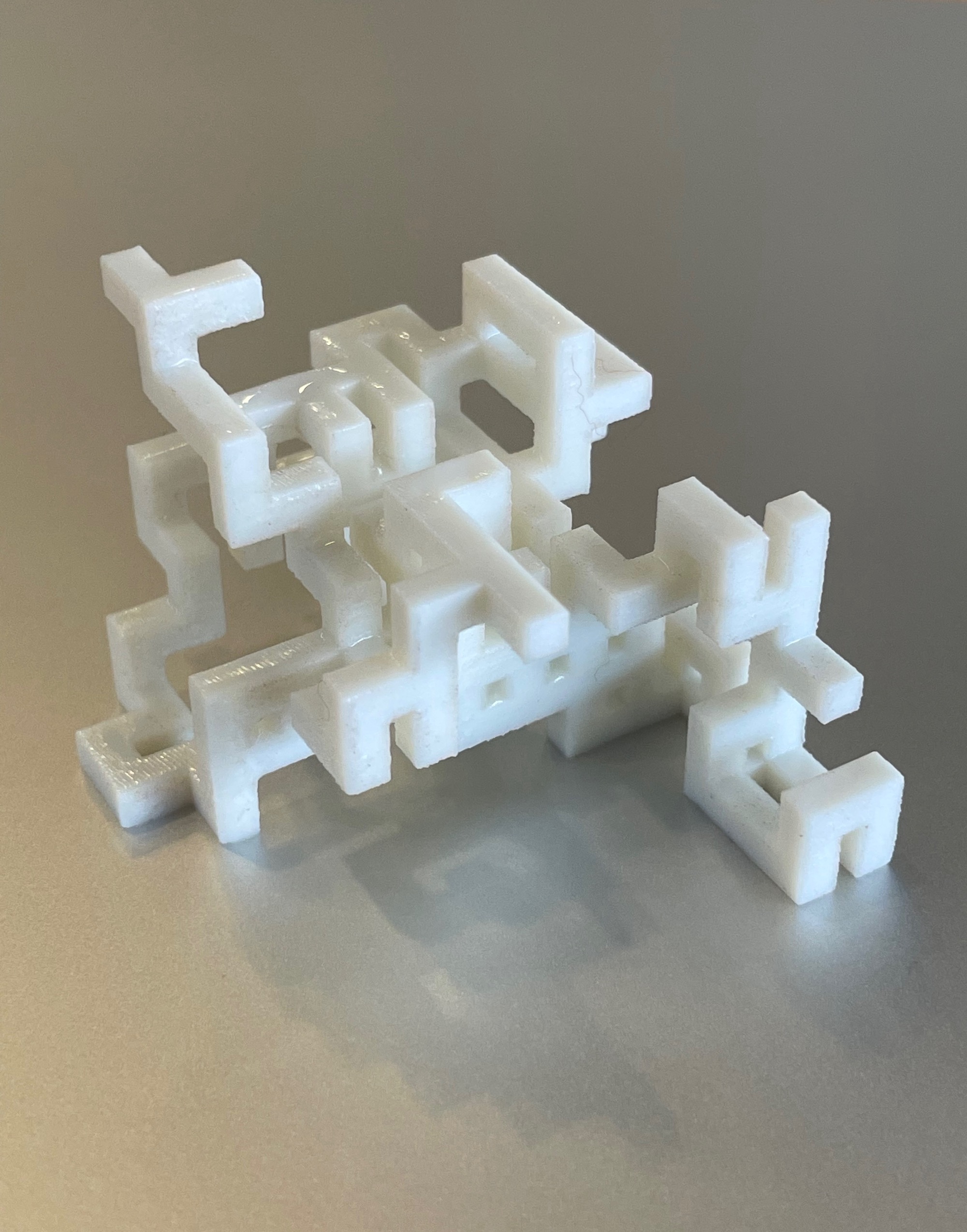
I needed to adjust the design to accomodate 3D printing. The design contains cantilevers everywhere, which required the 3D printer to create support material... If I had more time, I would have modified ran this experiment with shapes other than rectangular boxes to ensure that no horizontal cantilevers exists. In the end, the only changes I made to the design was making the rectangular boxes thicker to allow the structure to be printed at a small scale.

Scanning
I used the Artec Leo scanner to scan my body.
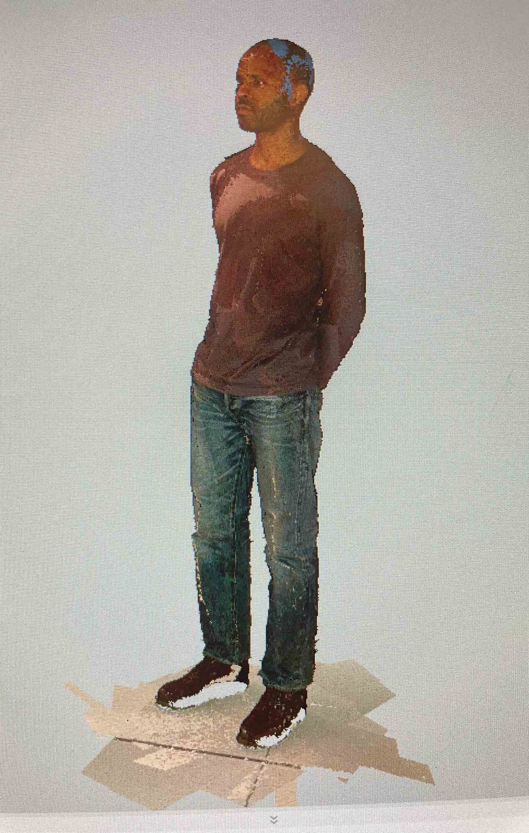
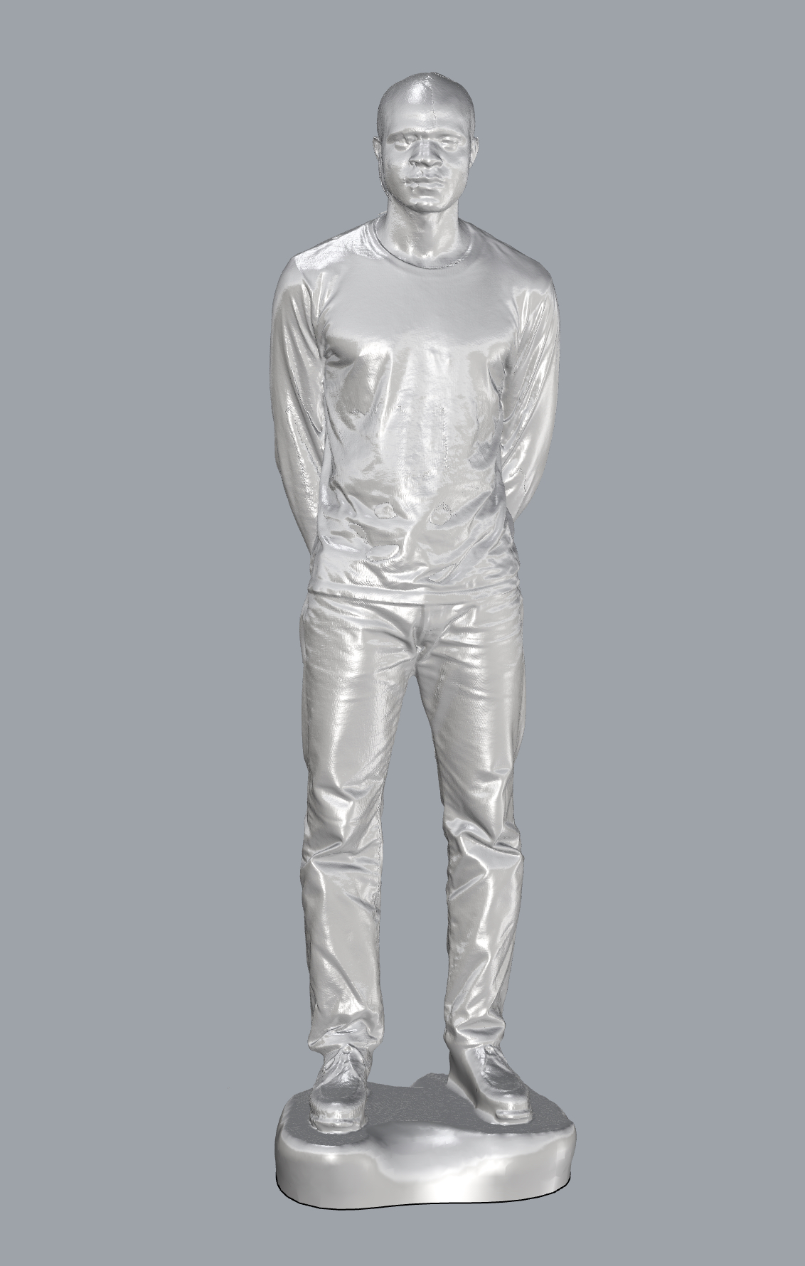
The scanner is fantastic and also quite fun to use. However, I ran into issues while trying to resolve inconsistencies across multiple scans of the same area on my body. I overscanned my body in an attempt to ensure that all of its details were captured. After merging all of the meshes in the Artec software, this resulted in visual errors in the resultant .OBJ, such as discontinuous surfaces on my shirt and repeated features on my face.
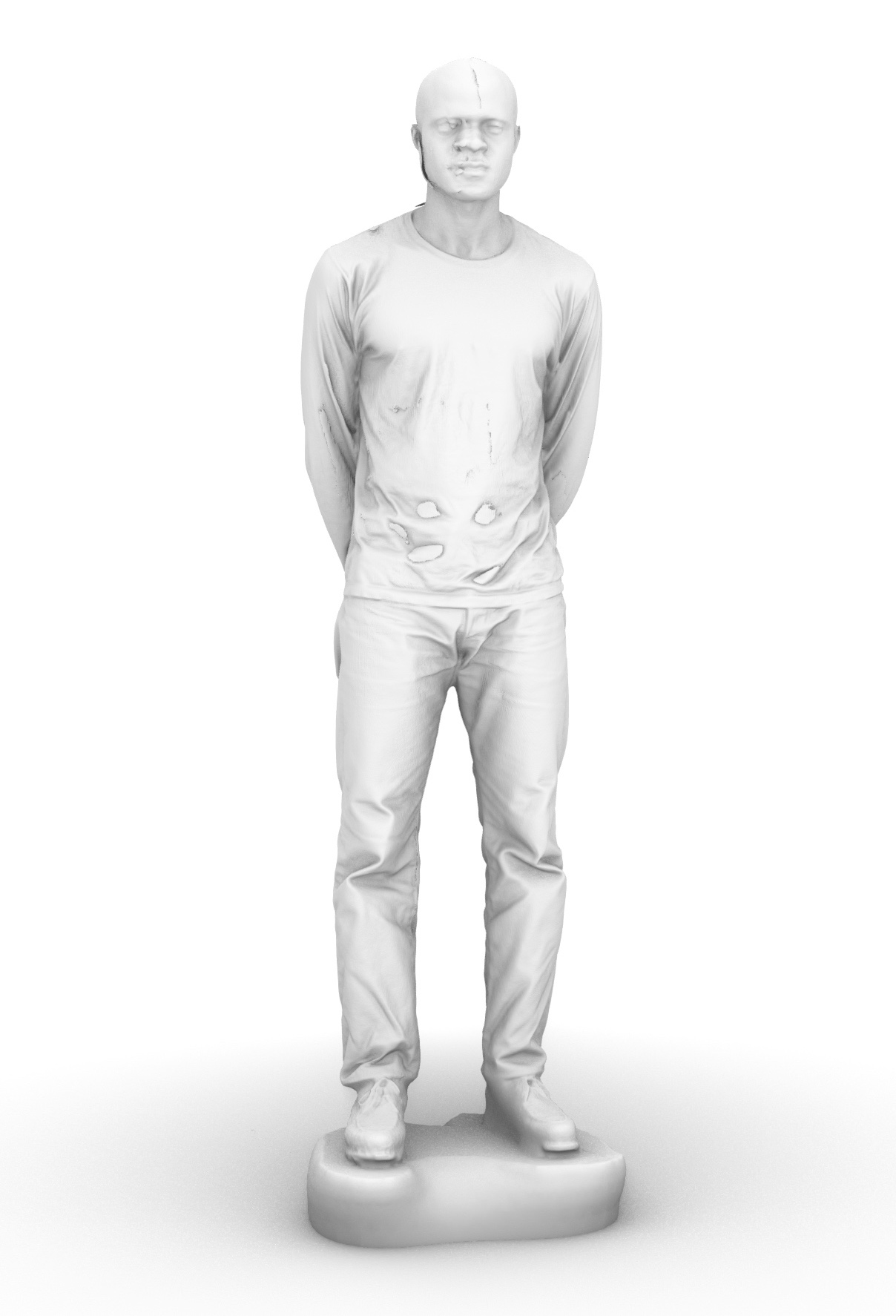
Were I to rescan my body, I would make fewer passes with the scanner and allow the software to resolve more of the uncaptured details on it's own.
Week 04
PCB Design
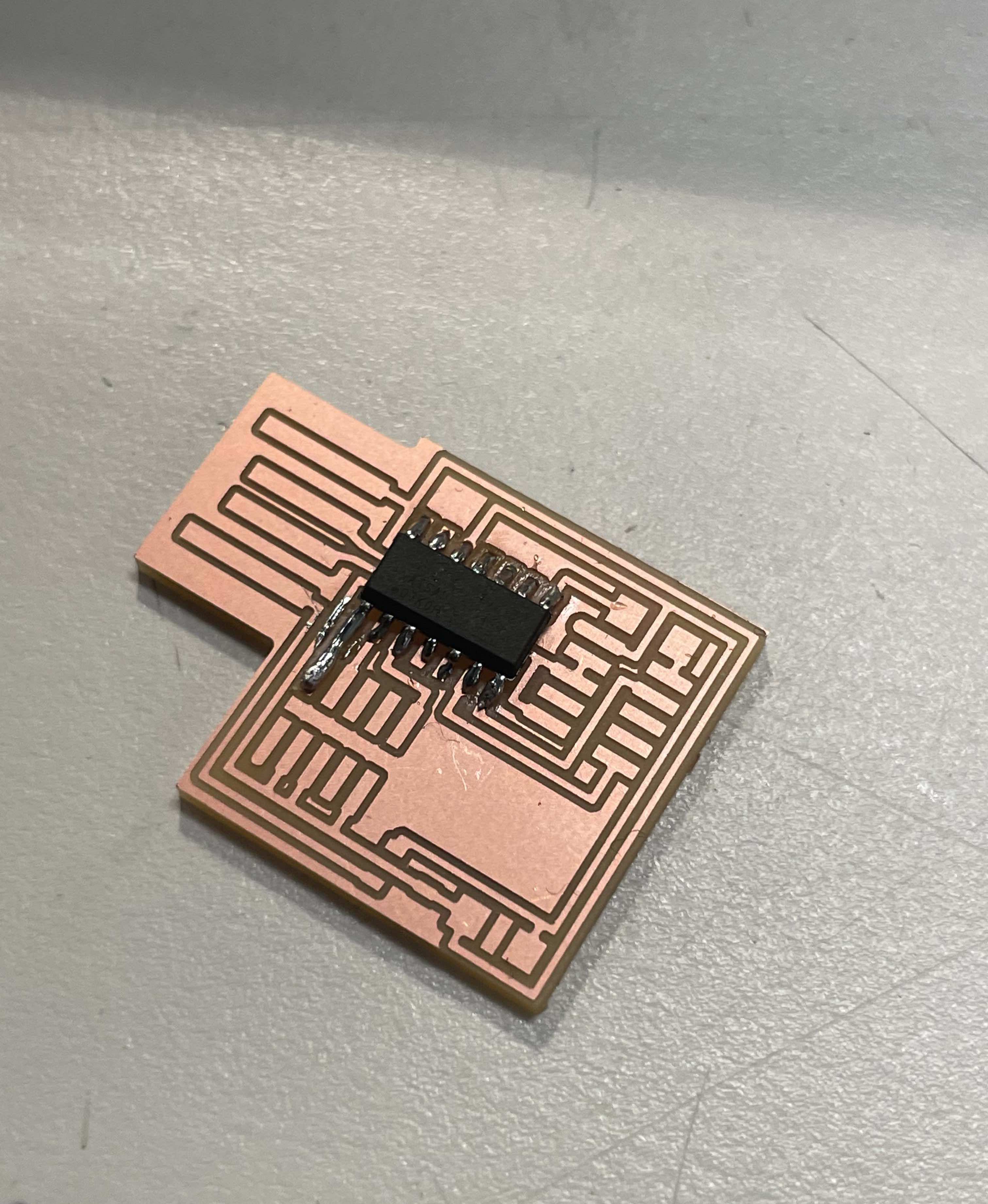
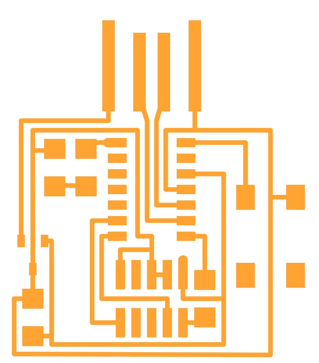
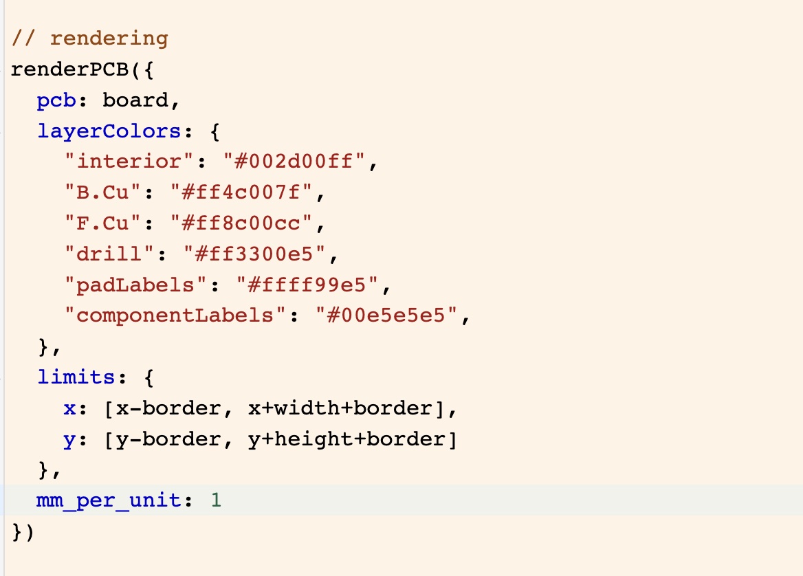
To design a PCB with an LED and button, I used the SVG-PCB tool. I liked the idea of modifying the PCB design using code and the potential for parametric circuit design that it offers.
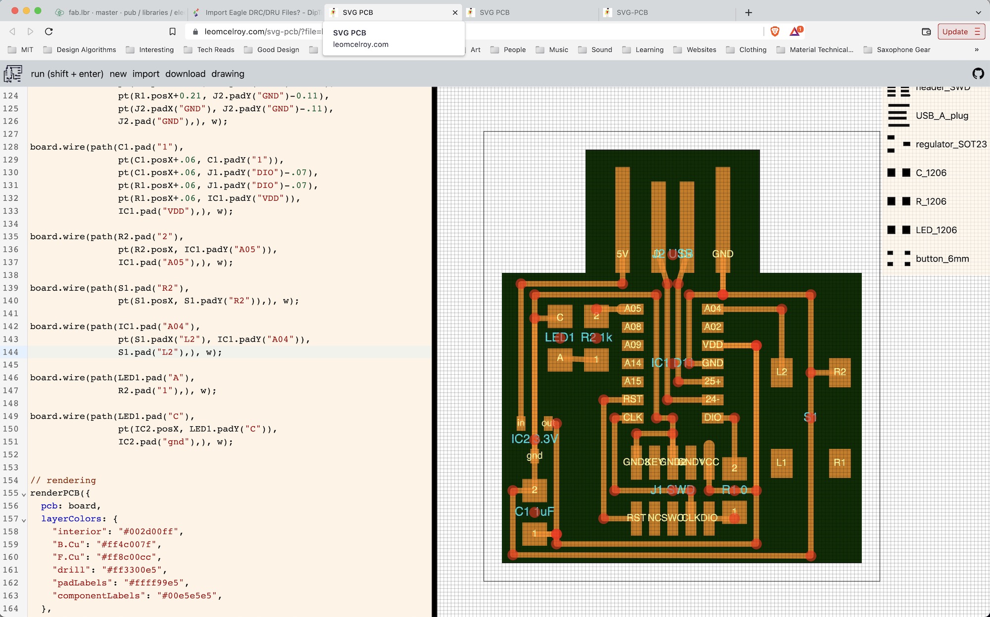
I was extremely impressed at how straightforward and intuitive the SVG-PCB tool is. Identifying the components in the code that I needed to place was simple and having all of my design parameters easily accessible in the code made debugging the milling process much easier.
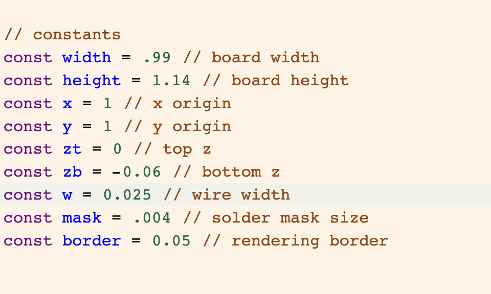
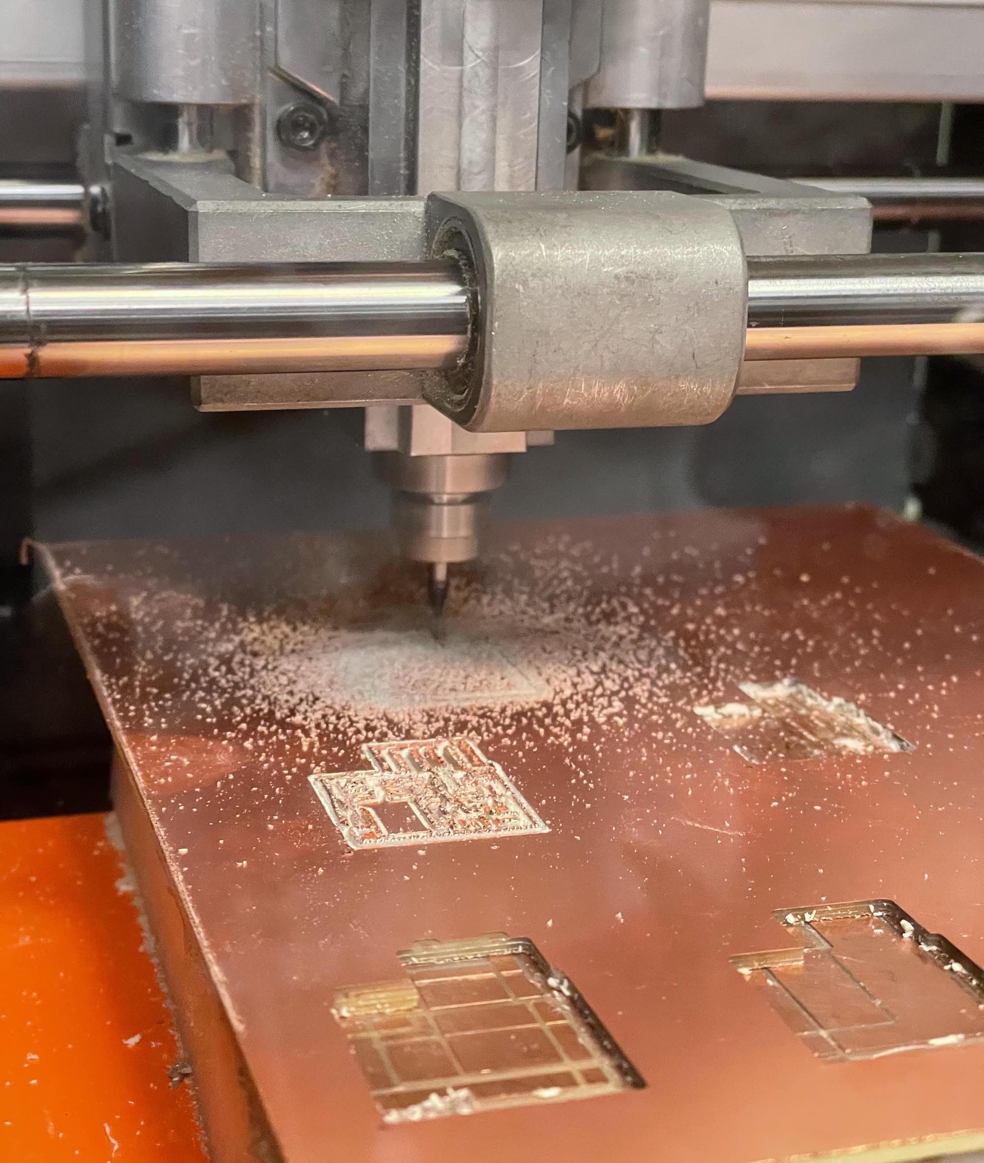
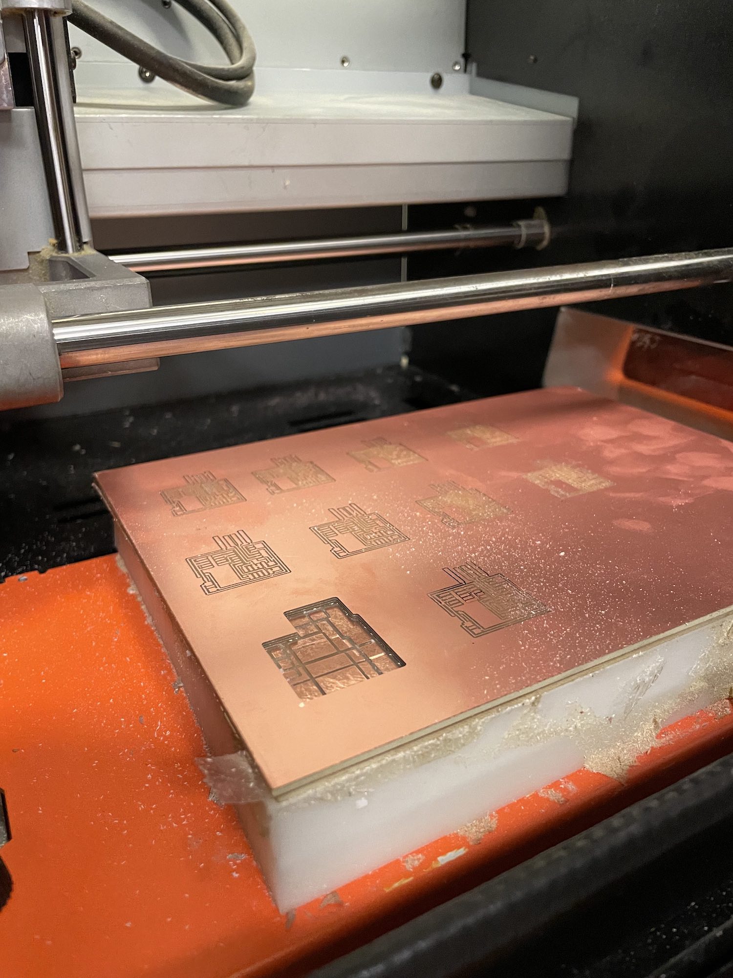
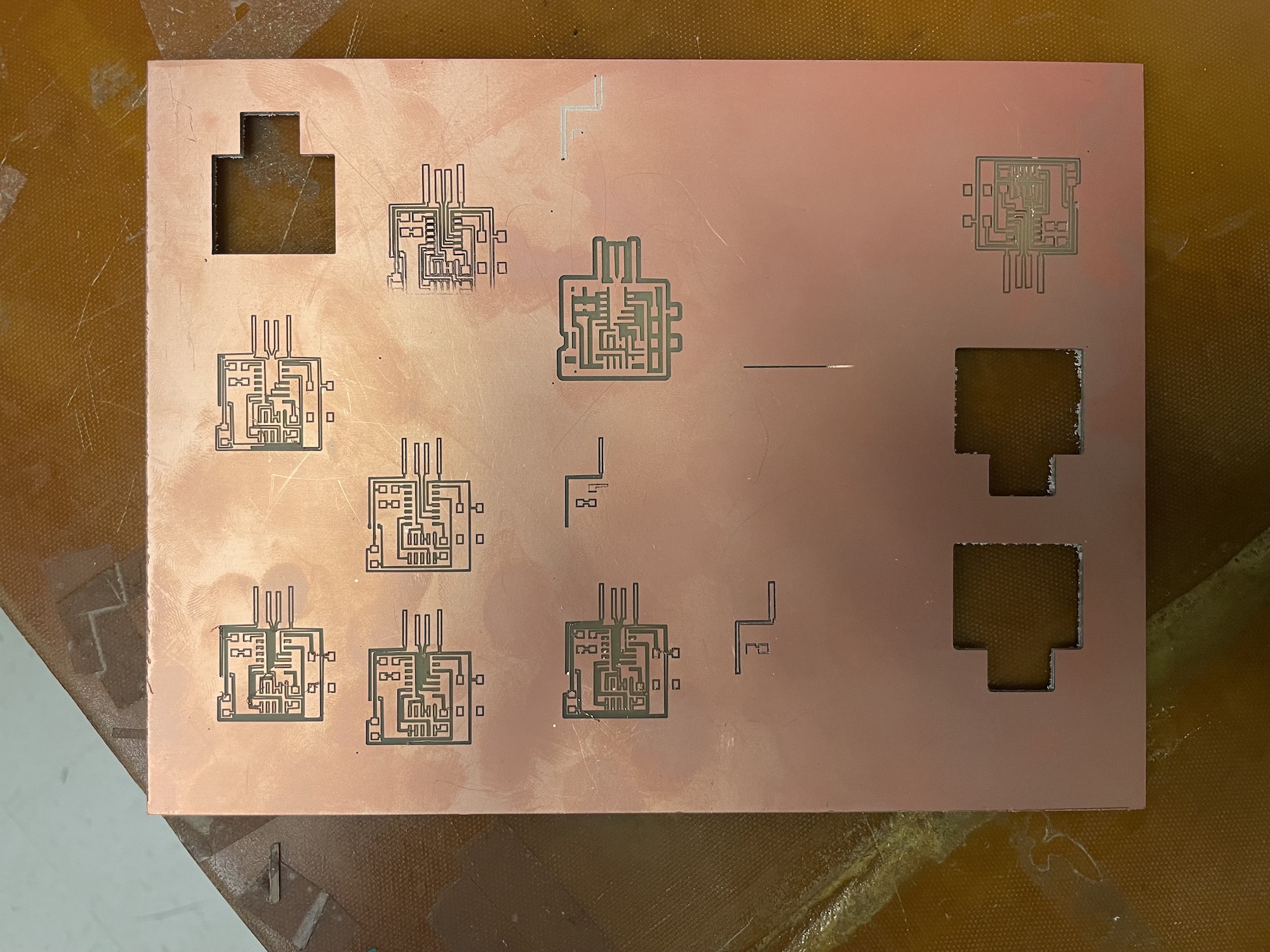
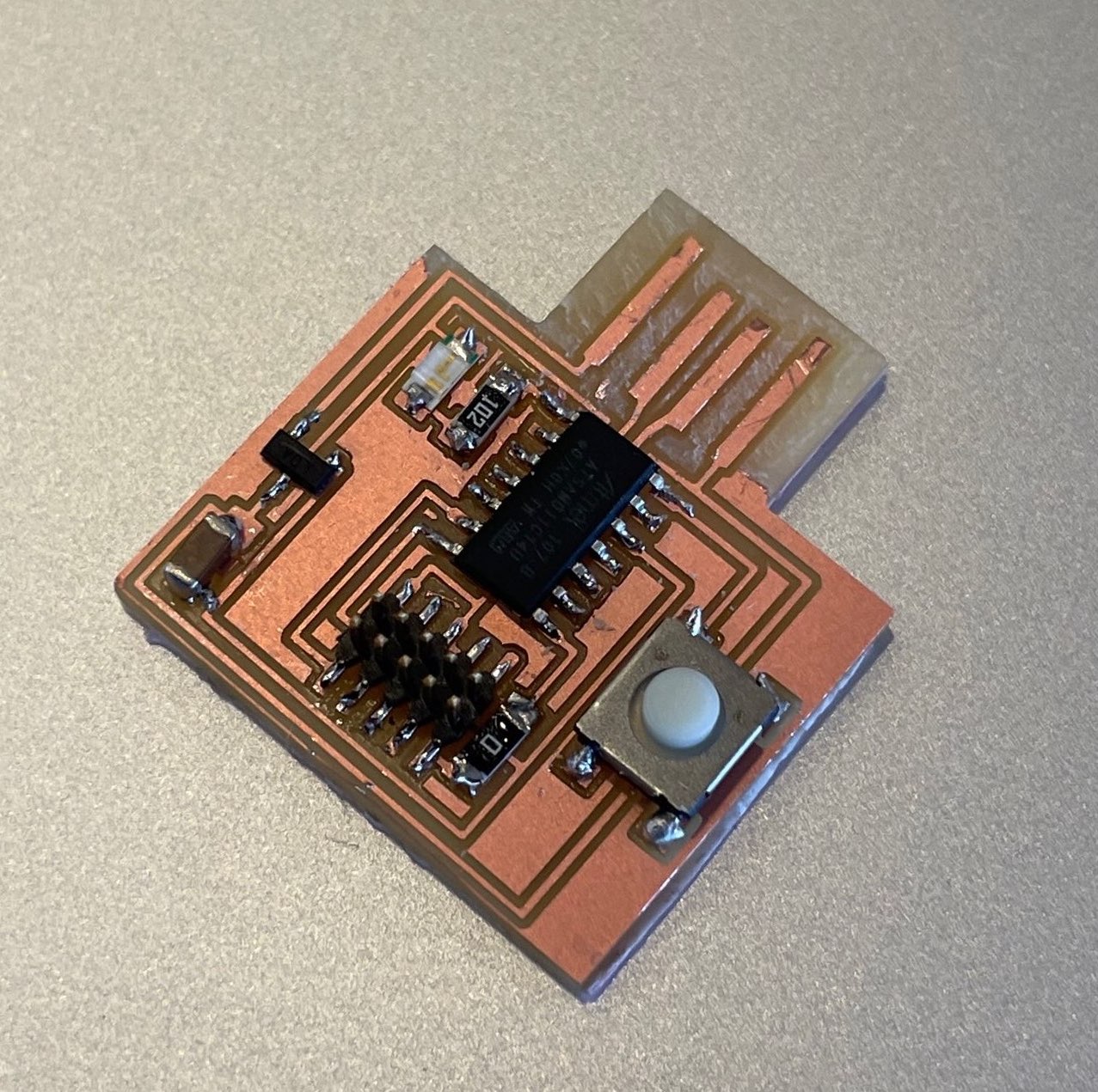
My final design was very simple. It was based off the PCB design for week 02, with an added LED, resistor, and button. To mill the board, I initially exported it as .PNG files.

However, when I imported the .PNGs into mods, the dimensions of my design were much bigger than anticipated (384.5mm x 437mm). This was because the default units in SVG-PCB are set to inches. When I changed the default units to millimeters, the .PNG exported from SVG-PCB was a 42x48 pixel image, too small to catpure the details of the design. I posted an issue so that Leo and the developers could fix the .PNG export functionality. While they fixed the bug, I used the .SVG export and mods program to cut my board.
When cutting my board, I ran into many hurdles ensuring that design was cut accurately and that the traces remaining in tact.
At first my, the tool paths were too close to leave adequate traces. I tried addressing this by adjusting the wire width design parameter.
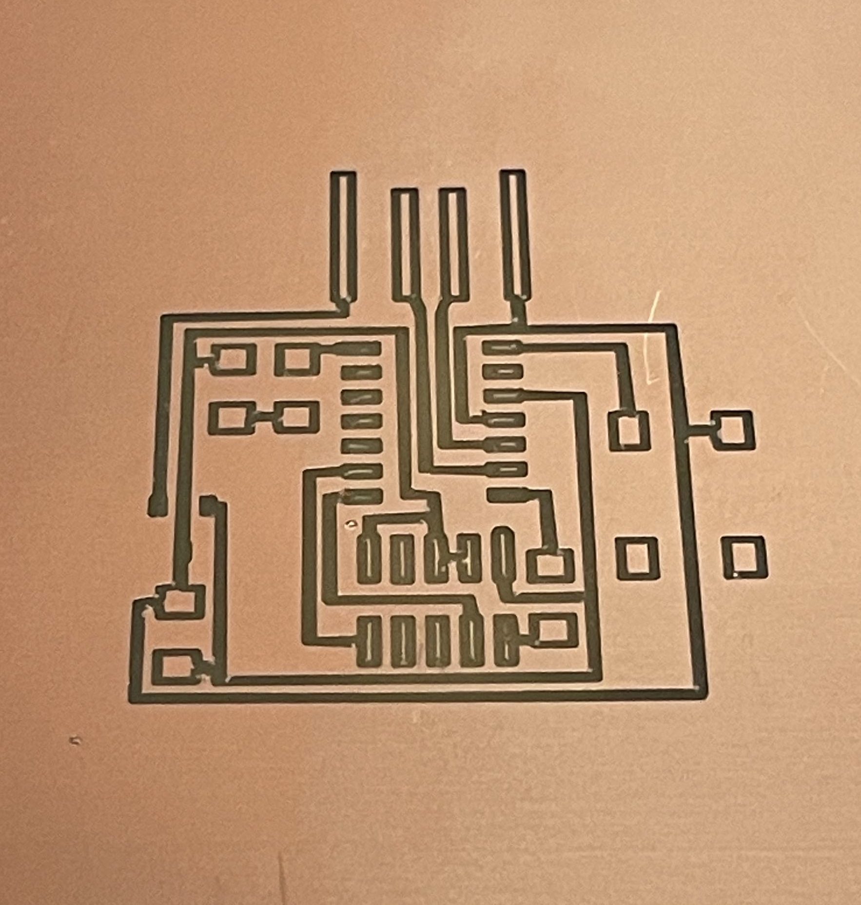


At thinner wire widths the paths did not appear at all when milling. At wider widths, the paths were not adequately separated. Eventually I solved the issue by using the "invert" feature in mods and adjusting the threshold value used to interpret the .SVG and represent the traces.
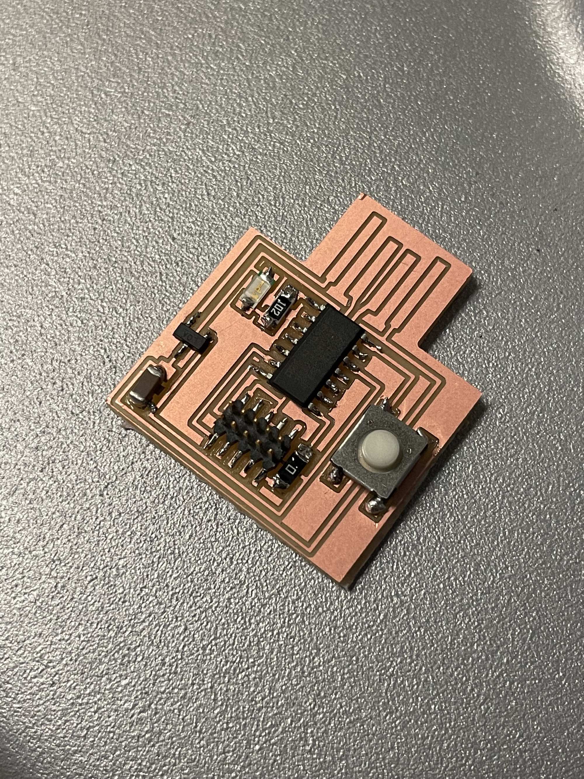
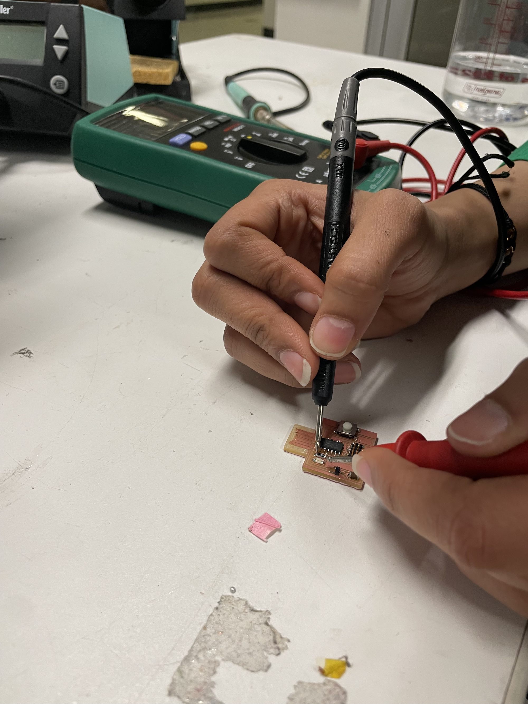
I soldered the board and used flux to ensure clean connections. I scraped away the excess copper at the USB connection point. Alongside a classmate, I also used the multimenter to ensure that all important pathswere conductive.
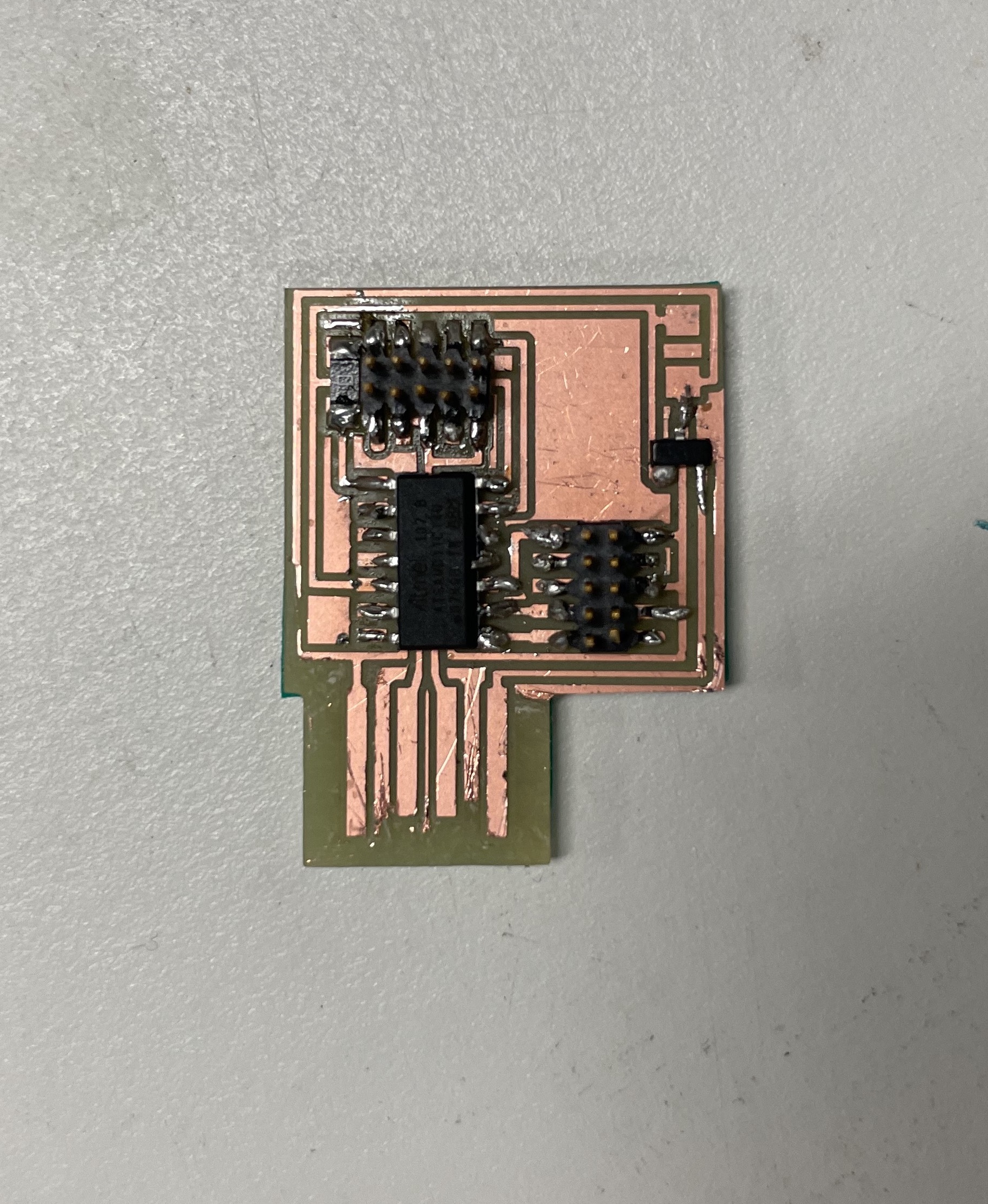
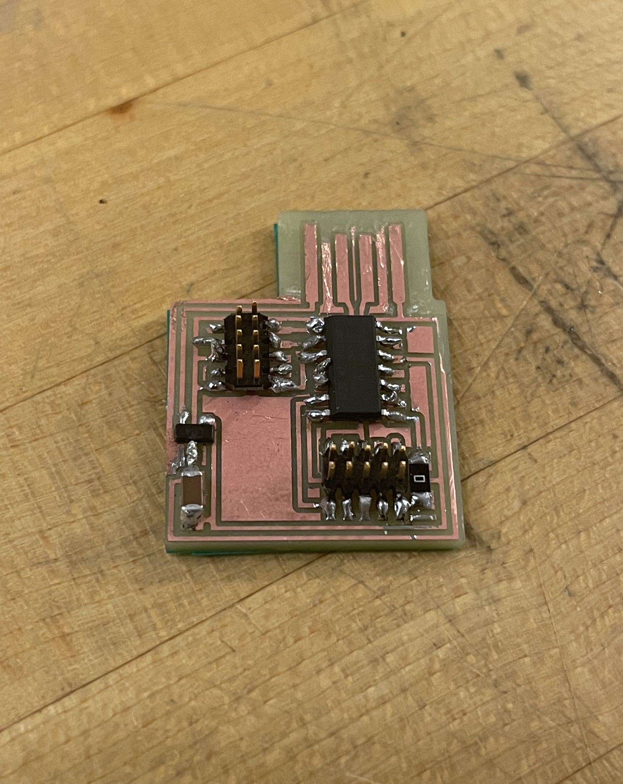
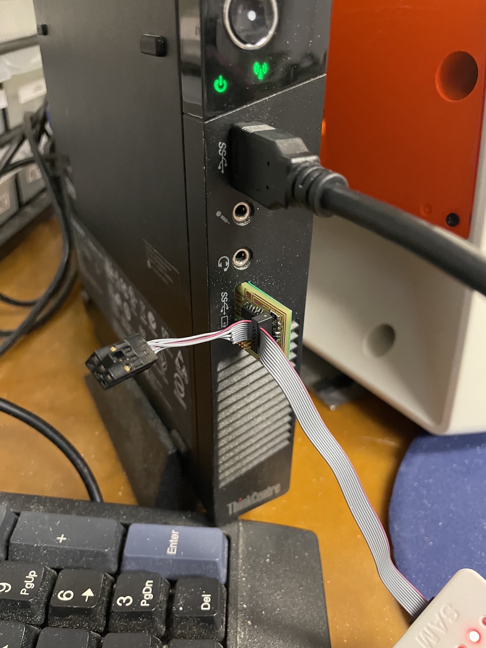
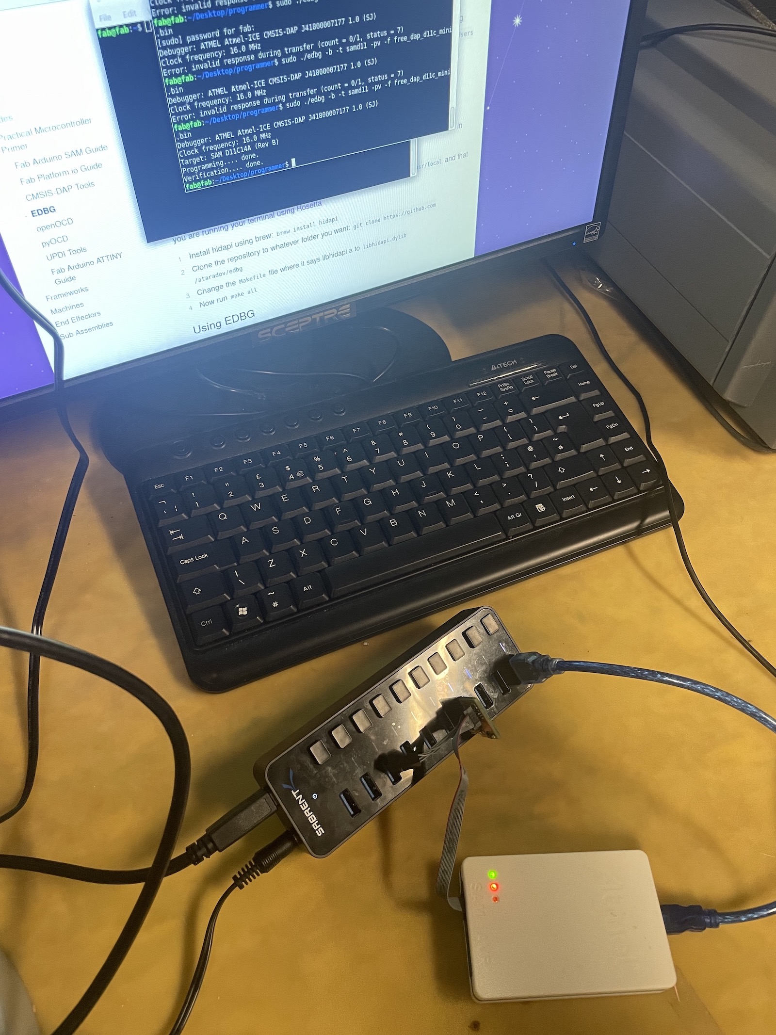
At this point, I began to encounter issues loading the firmware onto the SAMD11. My previous microcontroller seemed to work fine. This time, my device was identified by the Amtel hub, indiciated by the green light, but I was met with the error "invalid response during transfer".
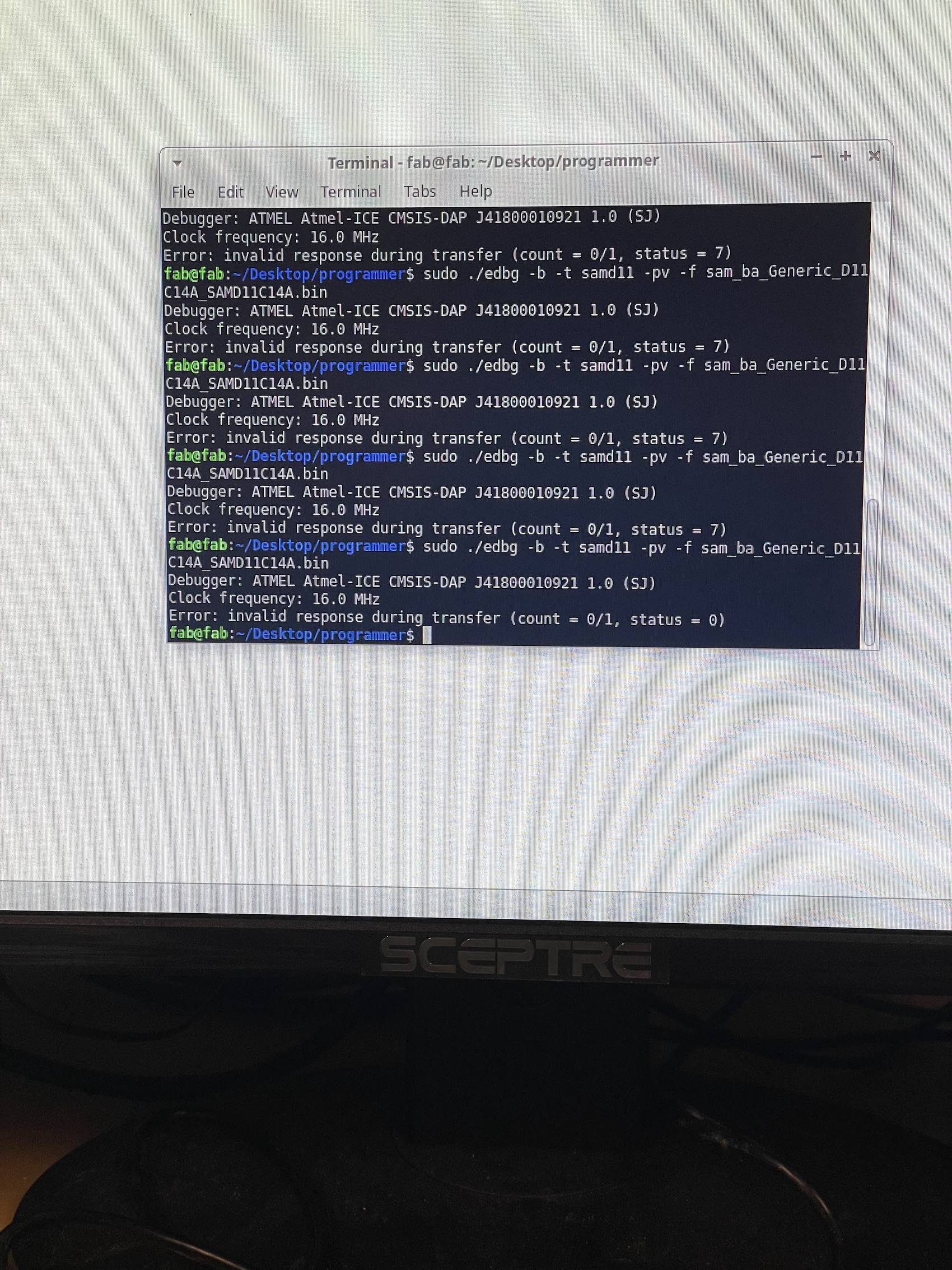
I went back and forth between the computer, multimeter, and soldering station to try and address the issue. I resoldered components, checked conductivity of the critical traces between the J-TAG Header and the Microcontroller, and tried different ribbon cables and orientations when plugging the device into the computer. Ultimately, I was not able to move beyond this step.
Despite the hurdles and shortcomings in this week's assignment, I learned a lot from the design and troubleshooting process and hope to design more complex circuit's in the future.
Week 05
Computer Controlled Machining
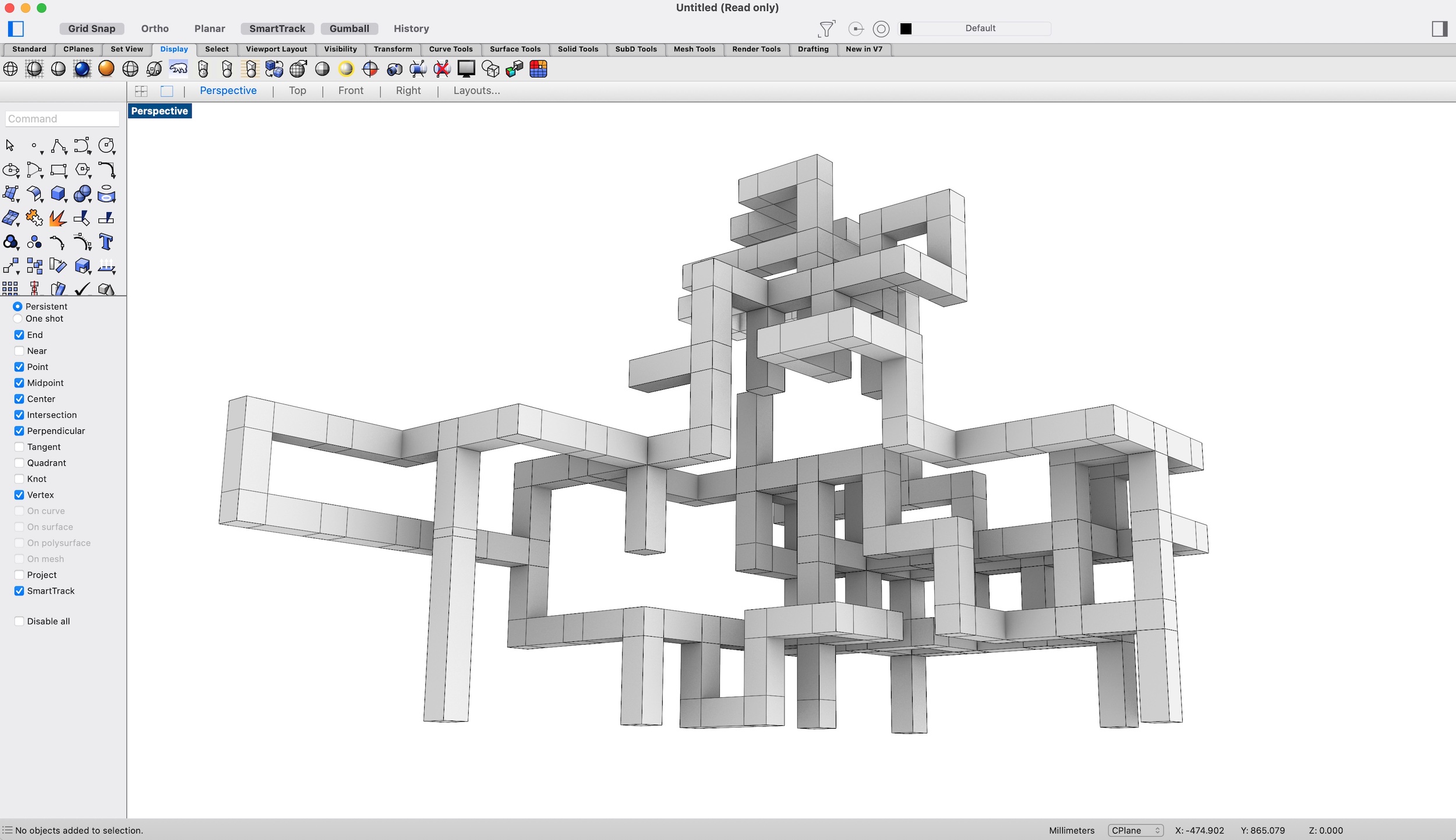
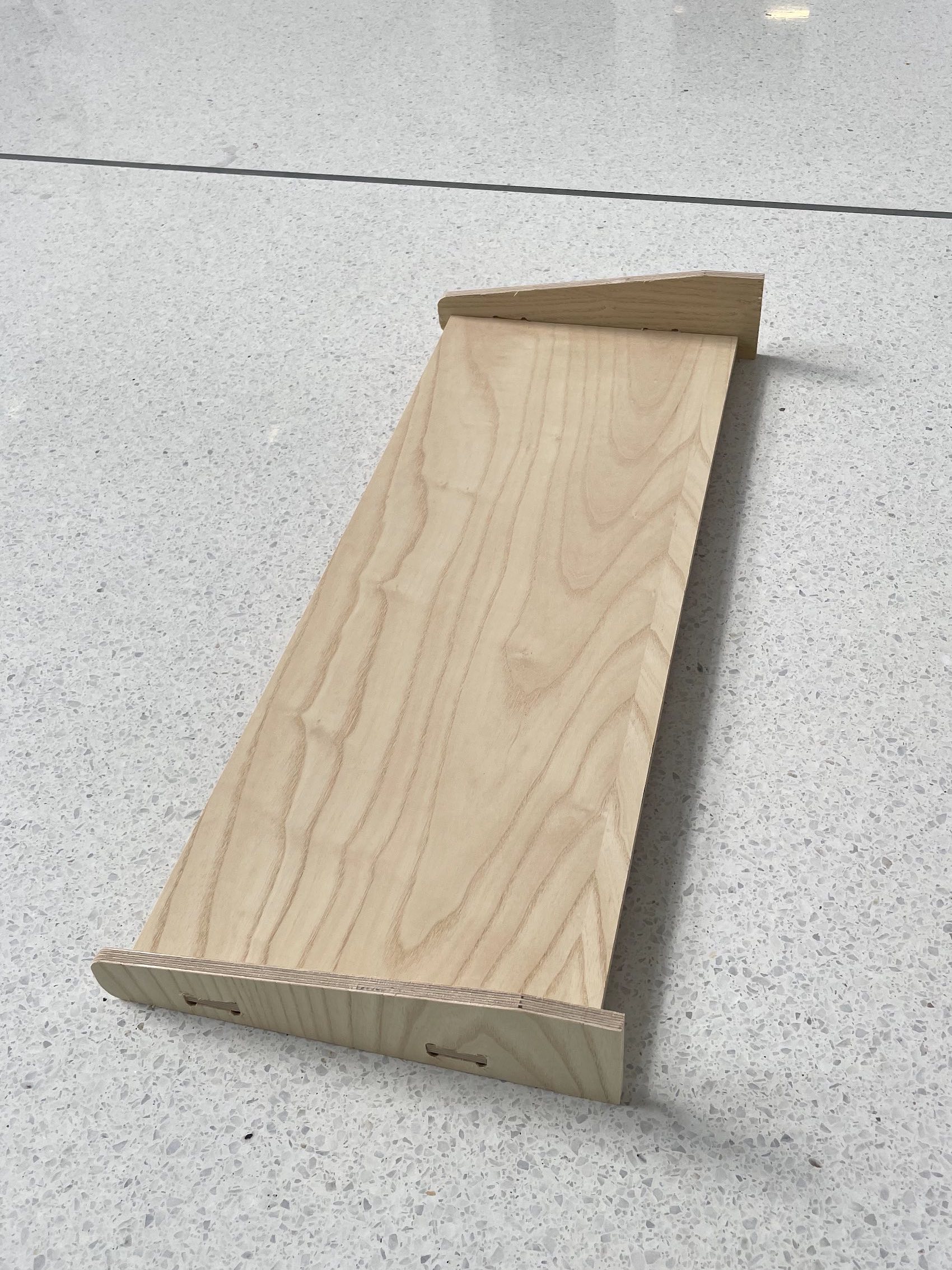
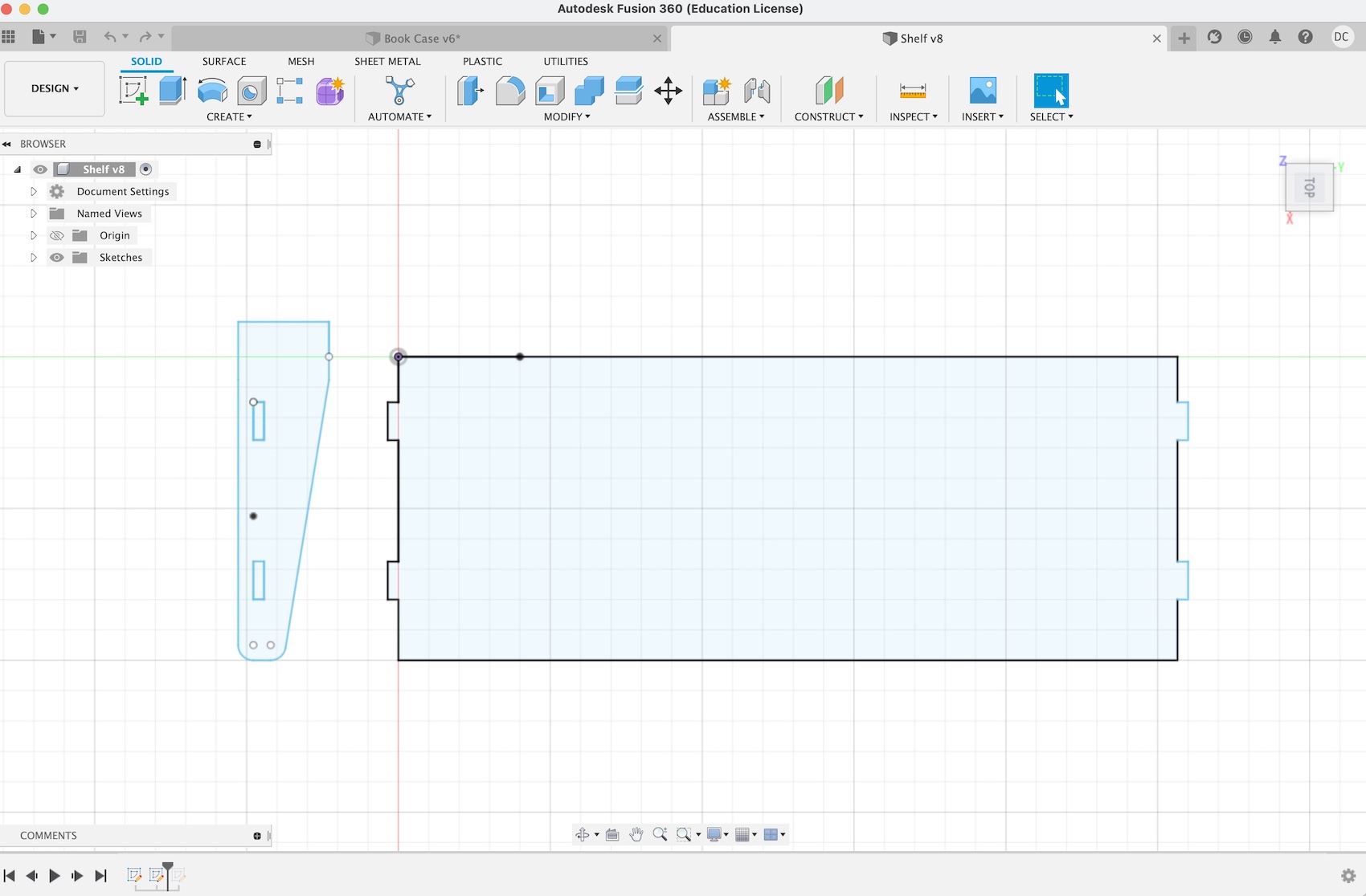
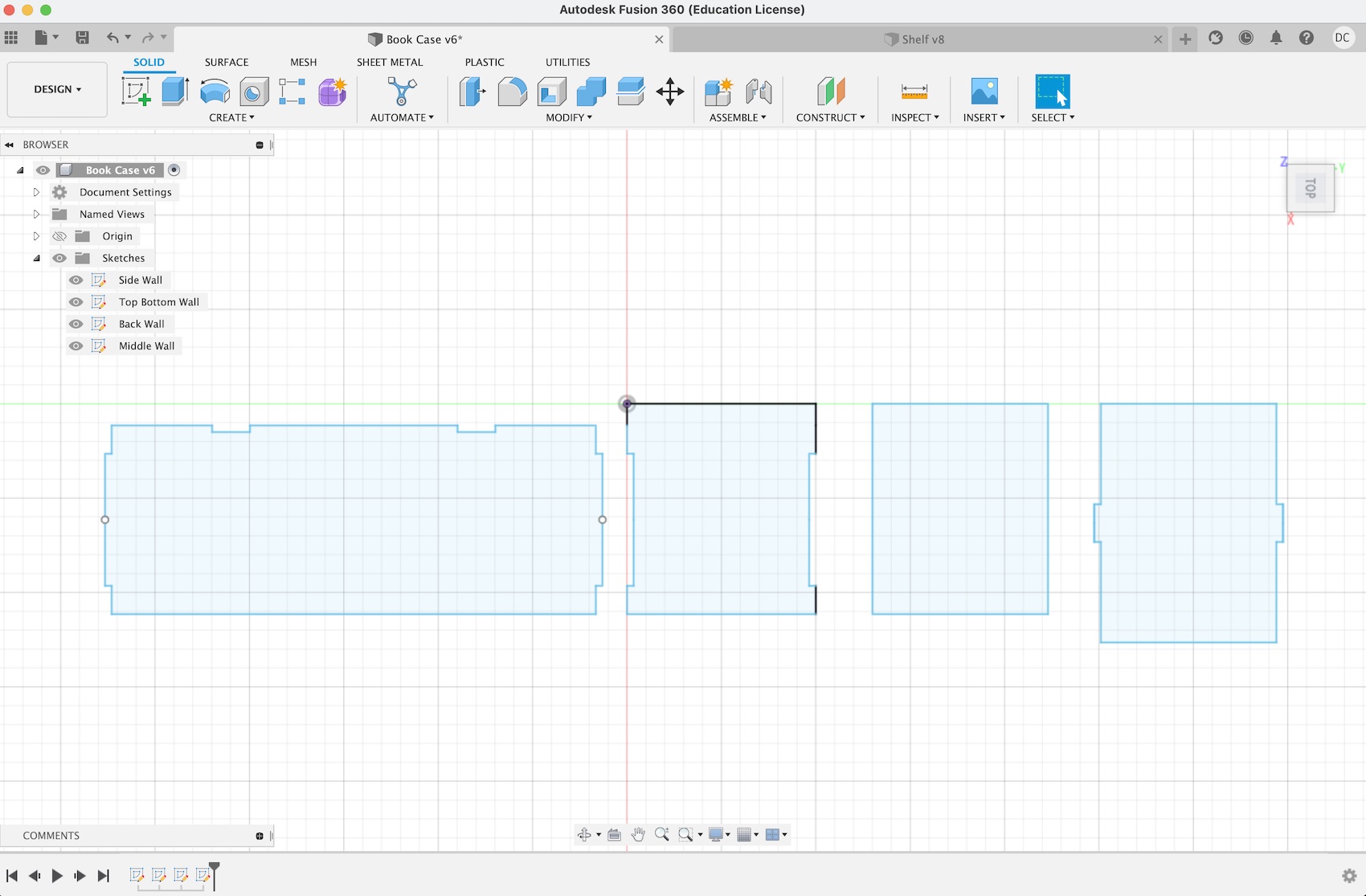
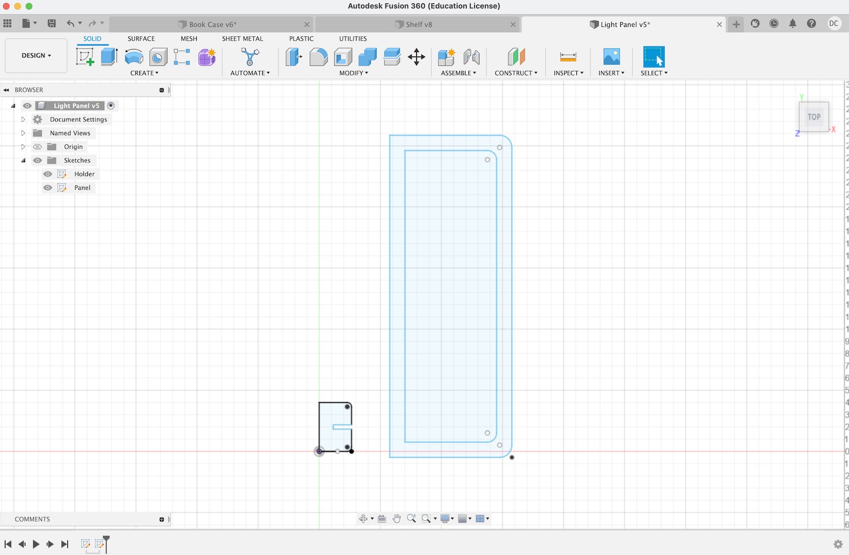
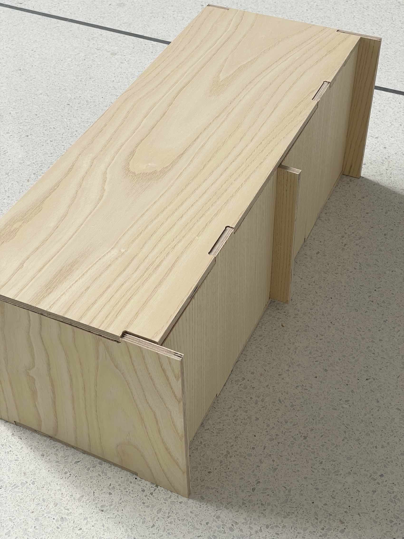
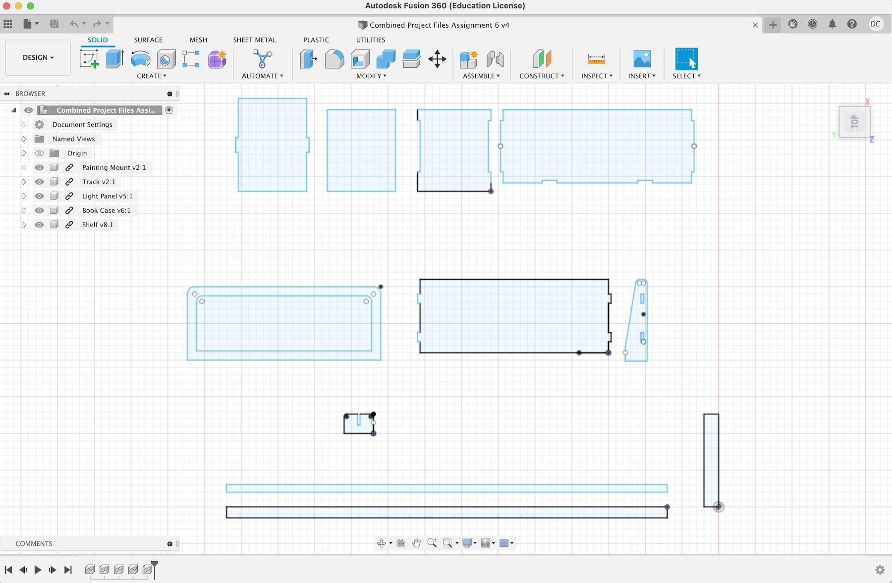
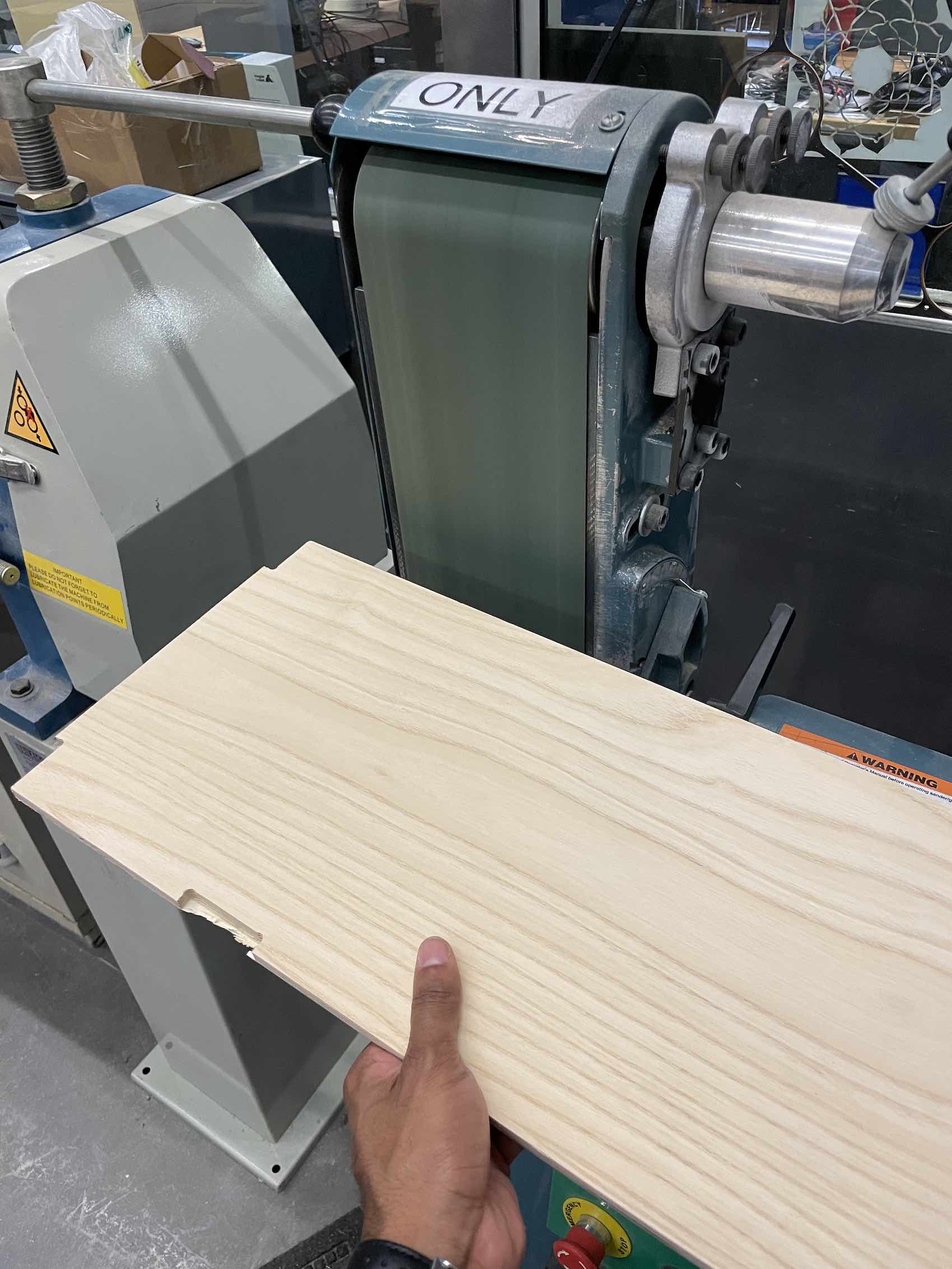
My focus for this week was to prototype the most fundamental elements in the wall system for my final project. This involved cutting the bookcase, shelf, light panel, and track component.
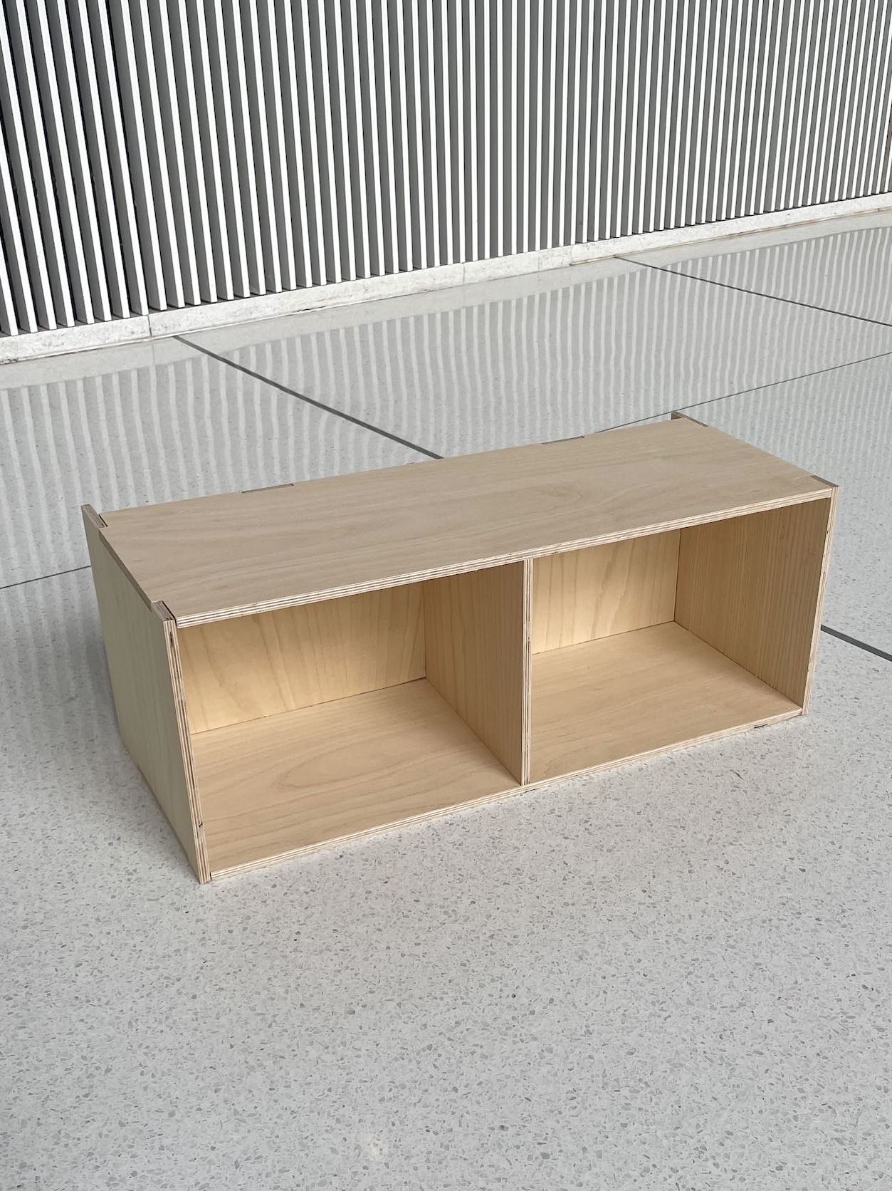

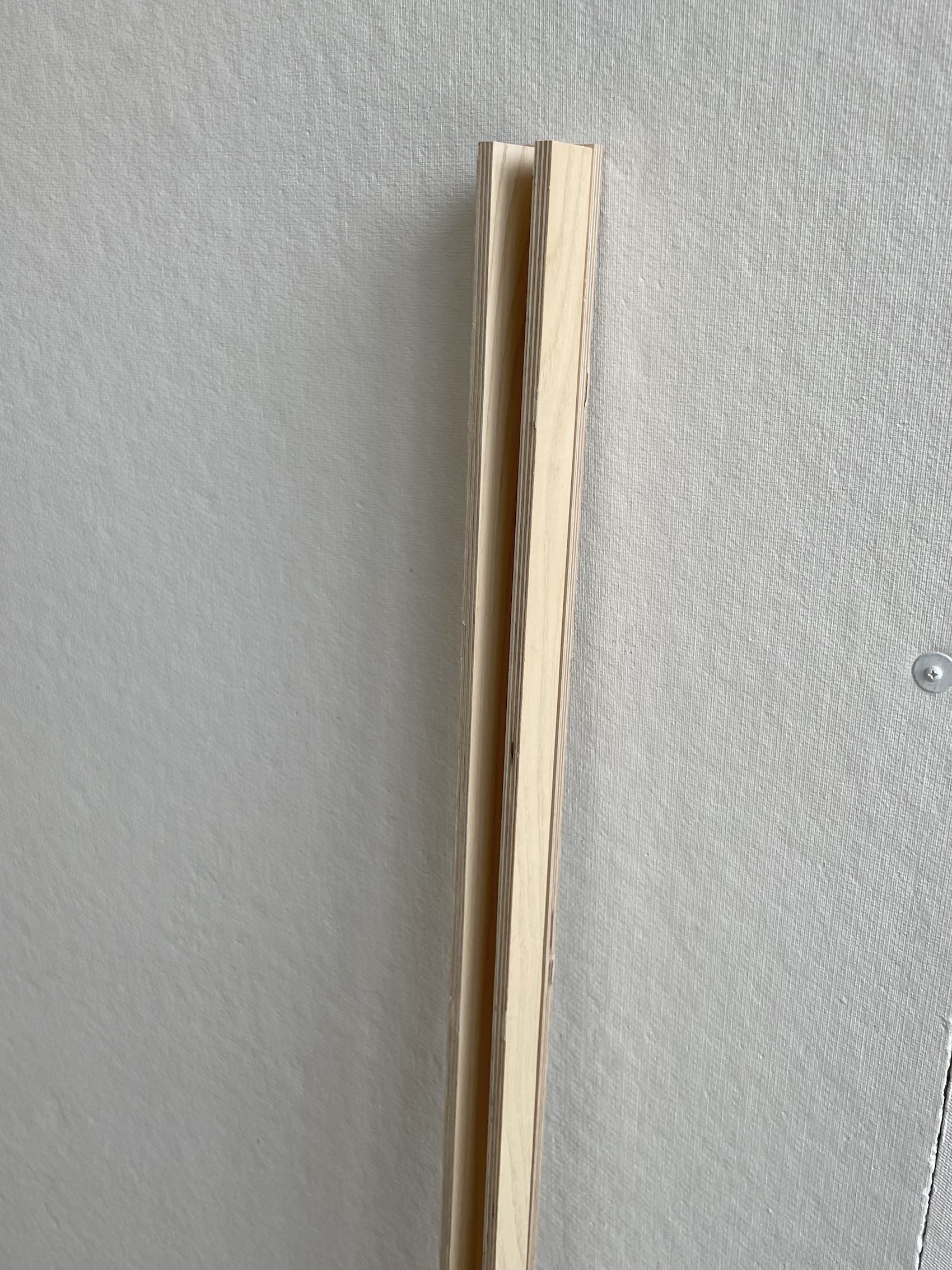
Material selection - I wanted to test my designs on the material I would cut my final project in, so I purchased a 4'x8' board of white ash plywood with 3/8" thickness as noted by the manufacturer. After receiving the material I measured it using the calipers and noted that the thickness was actually .35" (as oppossed to .375) and I created my design files according to this measurement.
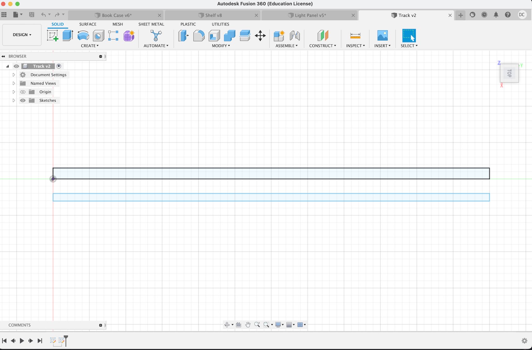
Each component is designed to fit into a wall-mounted track that enables them to be placed at the height and location of the user's discretion. The track will have evenly space holes for a 3D printed pin that will lock each component to the track. This prototyped track was cut using plywood, however I hope to use aliminum in the final version.
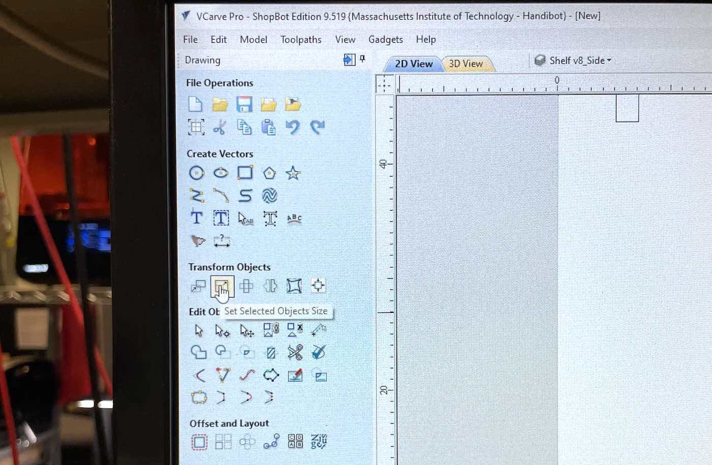
The processs of converting my design into G-Code for the shop bot was imperfect. I exported my designs as .DXF files from Autodesk Fusion in inches and imported them into VCarve Pro in inches, however the dimensions of my parts were consistently imported incorrectly. To fix this, I noted the dimensions of my arranged part file in Fusion, and scaled them to that dimension in VCarve Pro.
After fixing my files, the cutting process proceeded smoothly (aside from one error). We adjusted the machines total cut depth to .37in, which is .02 deeper than the material's thickness.
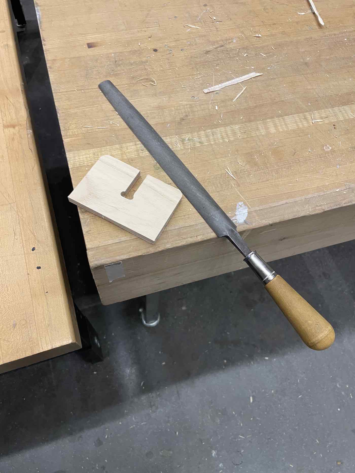
Unfortunately, after cutting and removing the screws to hold the material in place, we realized that many parts did not cut all the way through. This resulted in unsmooth edges that needed to be smoothed with the machine sander and file. This added an additional hour of labor after the cutting process but was an important learning experience.
Some of the components that resulted from this week's assignment will be used in the final project, while others will be recut to adjust dimensions and design for aesthetic purposes.
Week 06
Embedded Programming
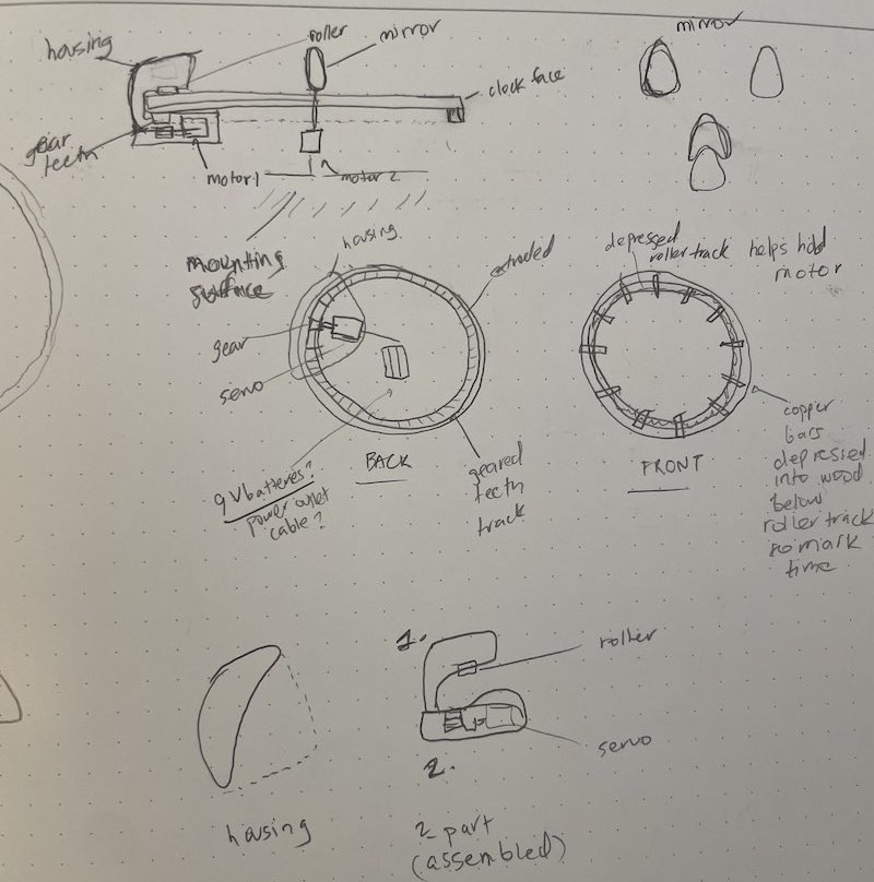
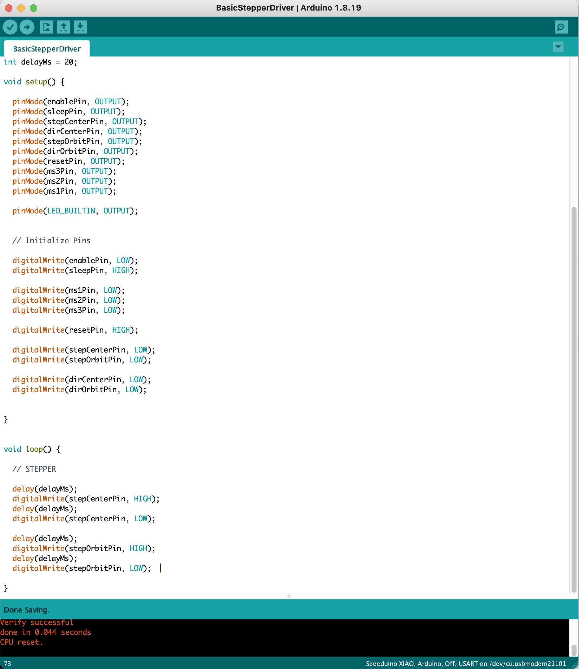
My goal this week was to cut, solder and program the PCB I would use for the light clock component of my final project. After sketching out some preliminary designs for the light clock, I decided that the PCB would need to control two servo motors and a small but bright light source.
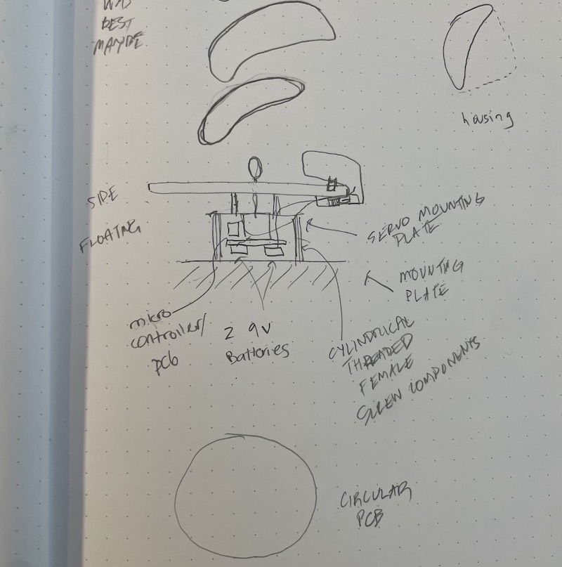
I decided to make a simple board for the light source portion of the project. This board would communicate with the main board that controls the stepper motors.
Because controlling an LED using code is relatively uniteresting, I decided to write code to control the two stepper motors I would use for my final project.
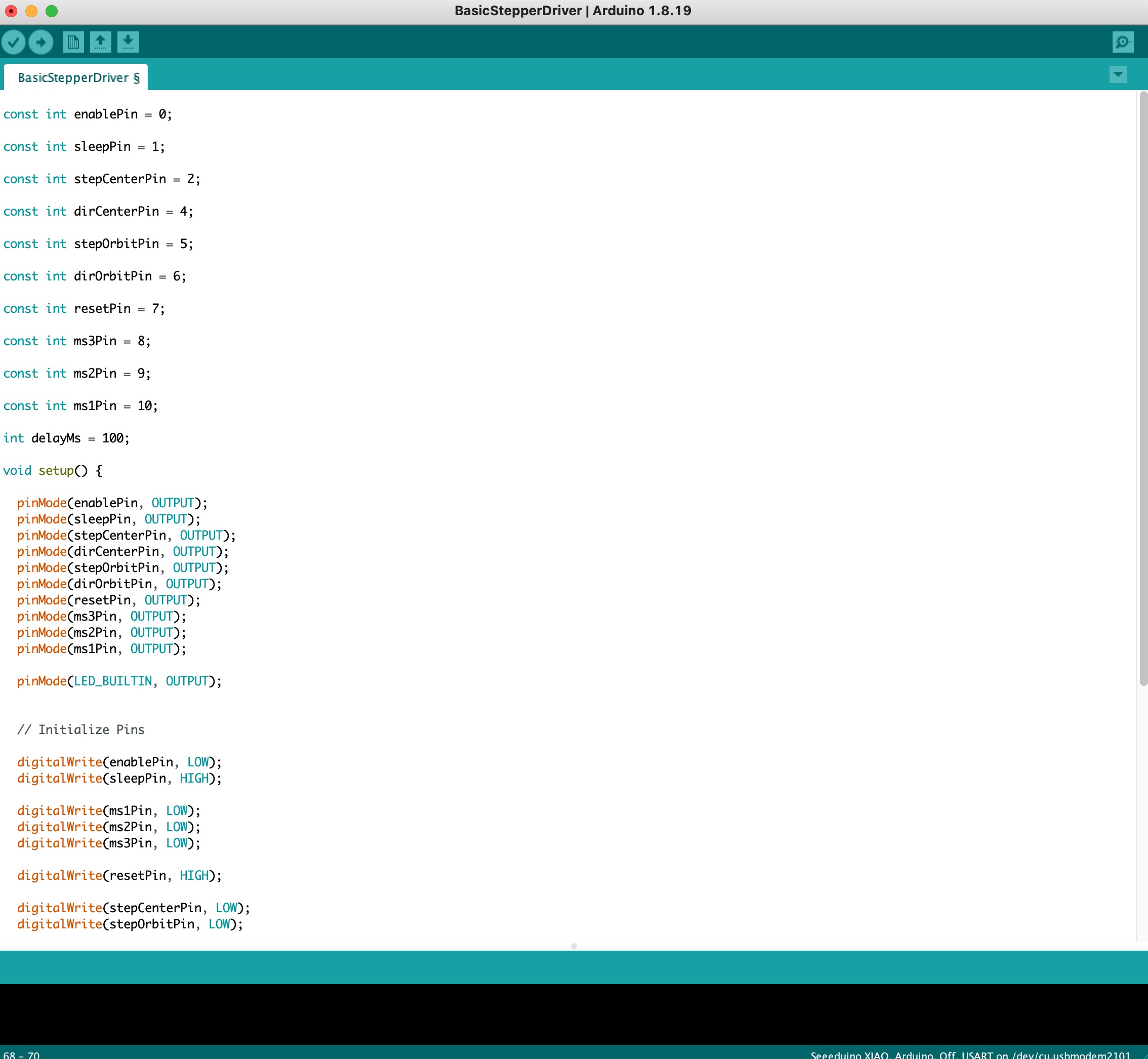
Assigning the pins appropriately for a stepper driver was relatively straight forward. The moving a stepper motor simply requires alternating the voltage on the step pins from HIGH to LOW with a delay in between.
Week 07
Molding & Casting
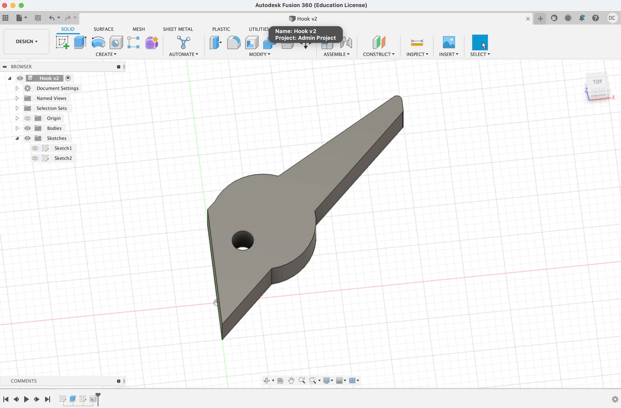
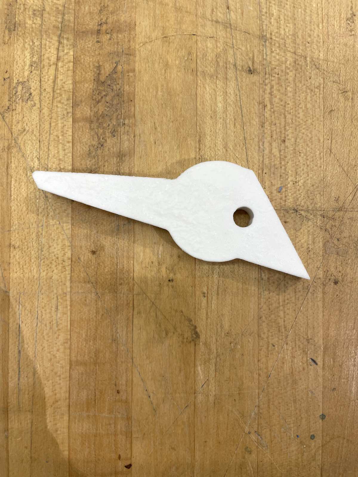
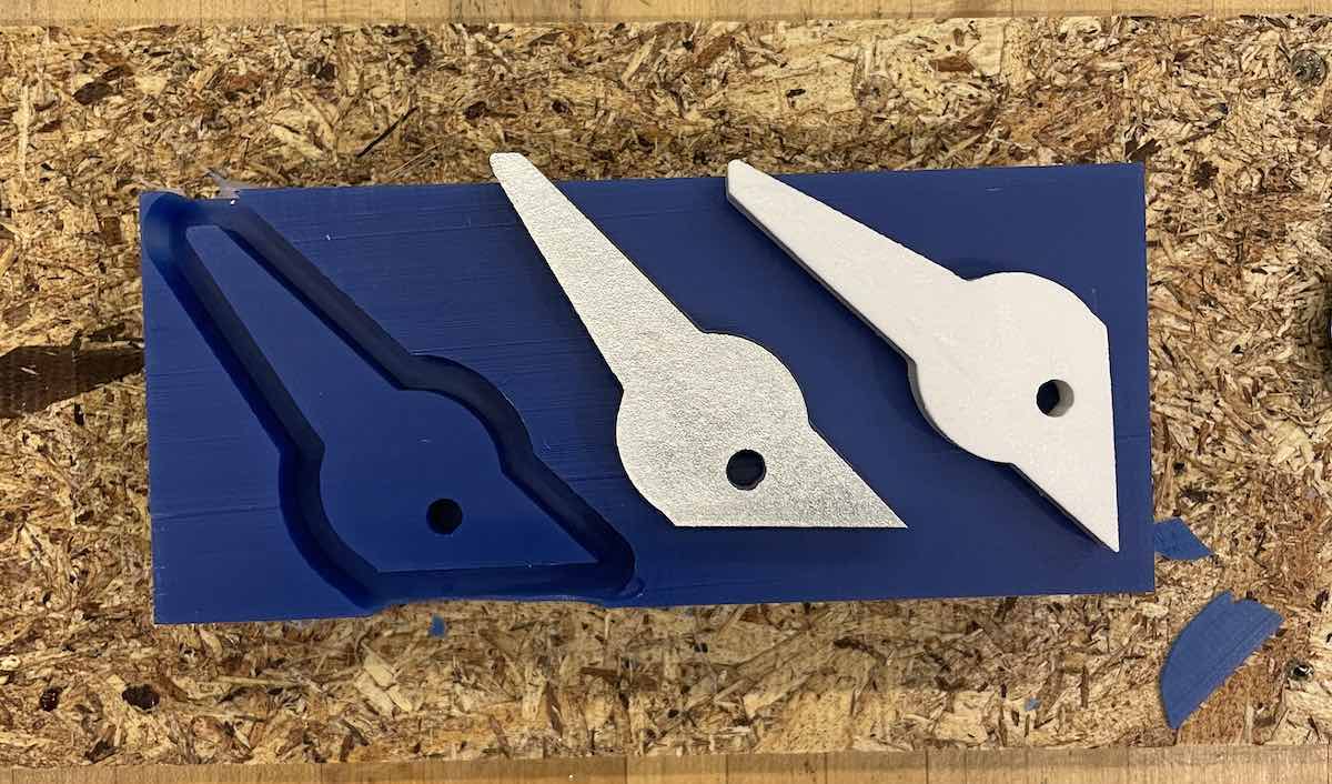
I molded and casted a coat hook in bismuth and hydrocal as an additional component for my final project.
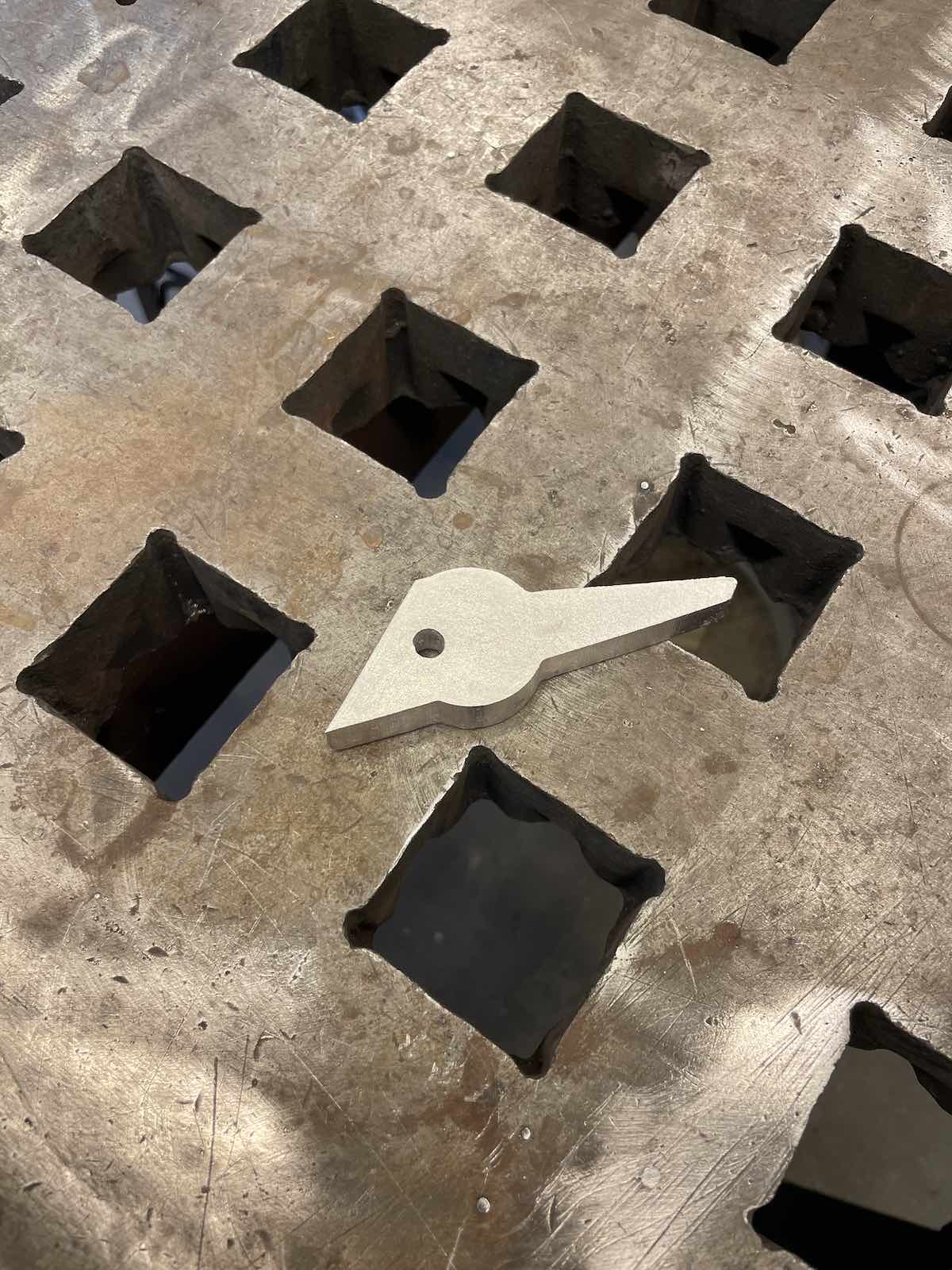
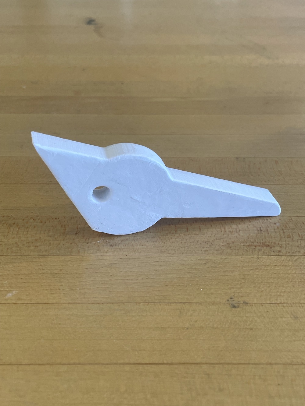
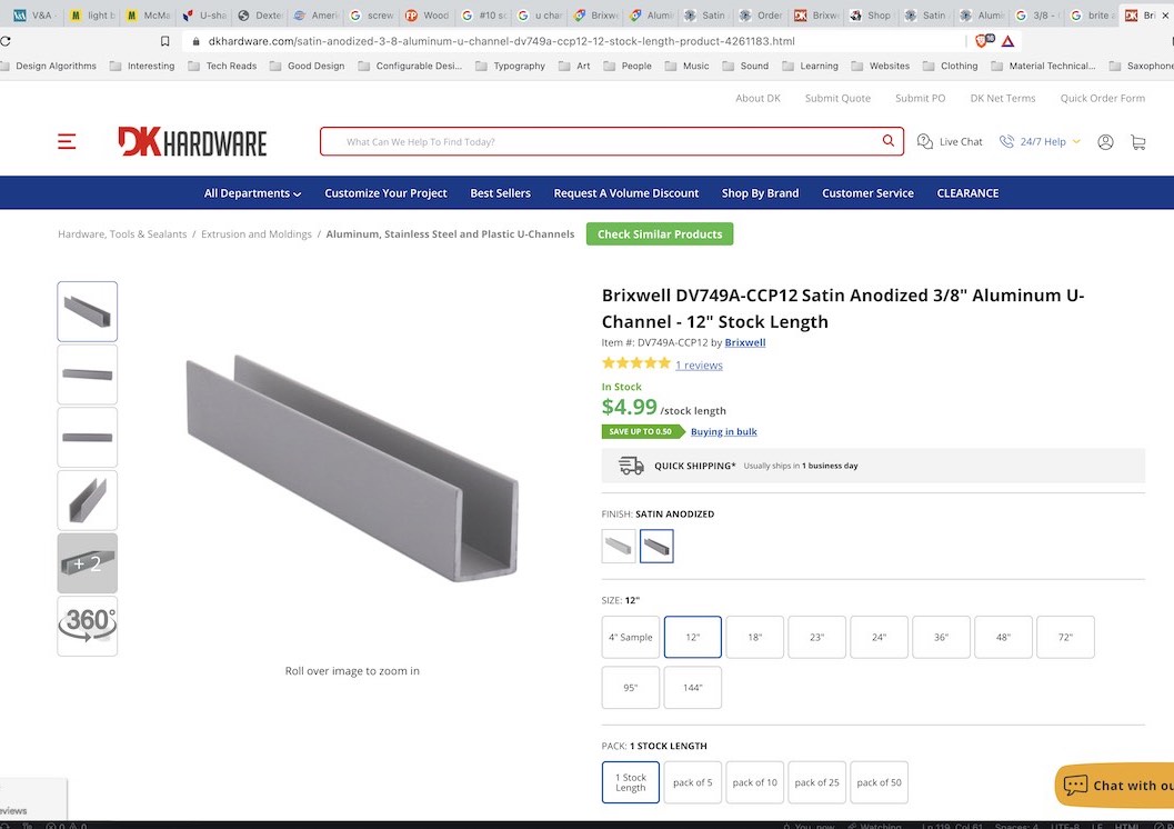
To design the hook, I needed to identify the mounting track that I would use for my final project to mount all of the components to the wall. I ordered samples of a low-cost aluminum U-channel track and I designed the part to fit the dimensions of the track. The track will be drilled with evenly space holes along each of its faces. One set of holes will be used to mount the track to the wall, and the other set of holes will be inserted with a pin to hold the wall components.
A coat hook is a very simple object. Many of the design decisions were arbitrary/aesthetic with regards to the hooks shape. The primary design requirements were the hole placement and size for the pin, and a flat surface where the hook could rest on the track and evenly displace any force applied to it.
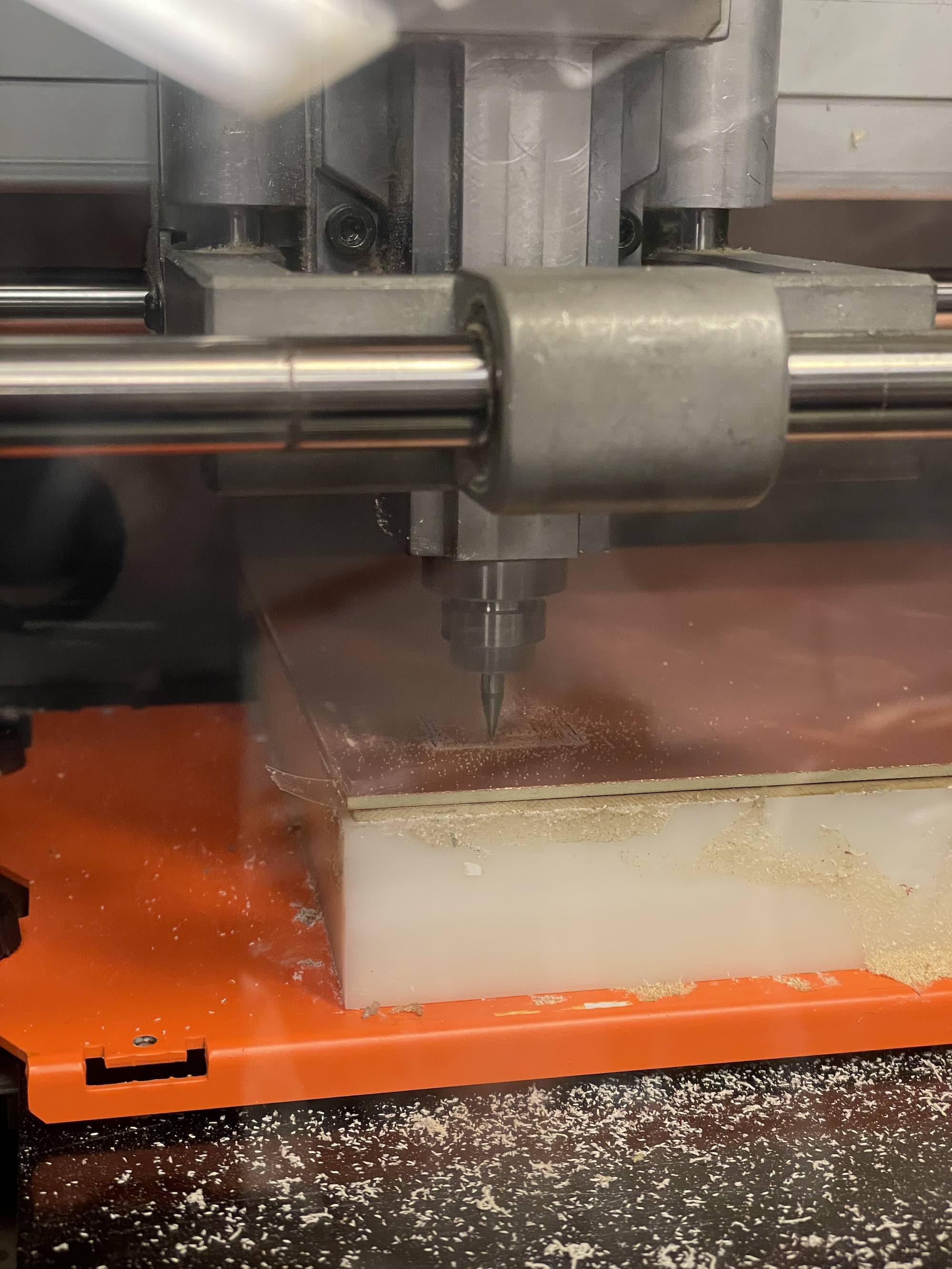
When preparing my files in Cut3D and milling using the Desktop Shopbot, I encountered an unusual error where if I sunk the model into the wax block by the recommened .2in, the result toolpath would make multiple point plungers along the edge of the shape versus smooth lines. To fix this, I sunk the model into the wax block by only .1in, which fixed the tool paths.
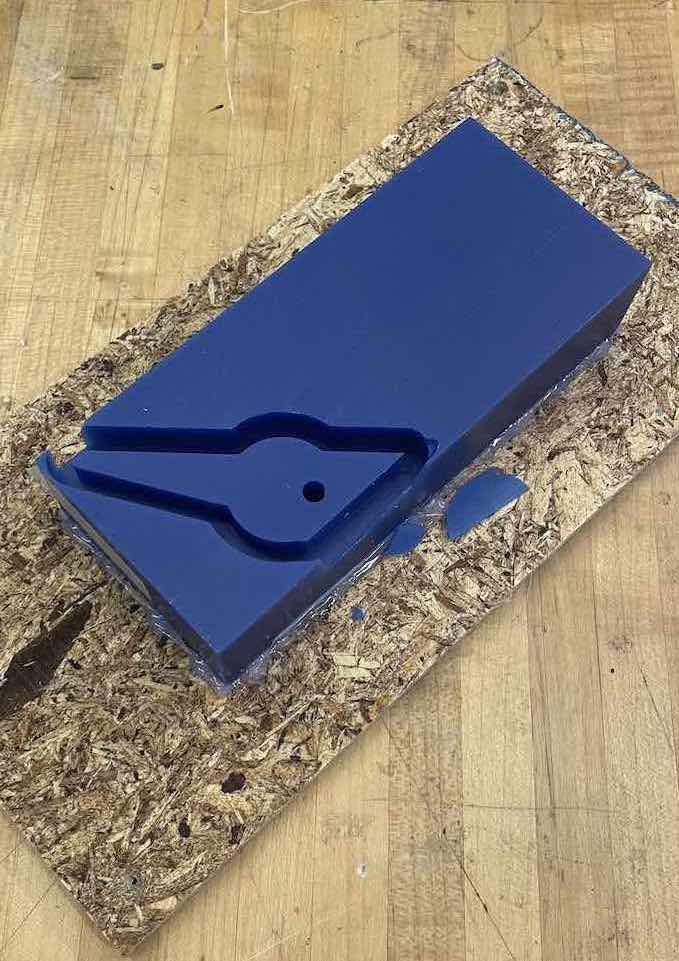
My toolpath ran very close to the edge of the wax block, and the walls of the block were so thin that they snapped off when I handled it. I had to use carboard along the perimeter of the block to reinforce it before mixing and pouring the oomoo.
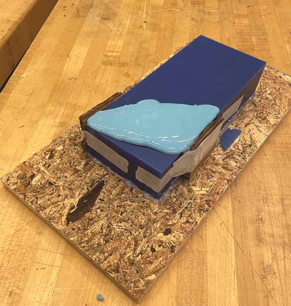
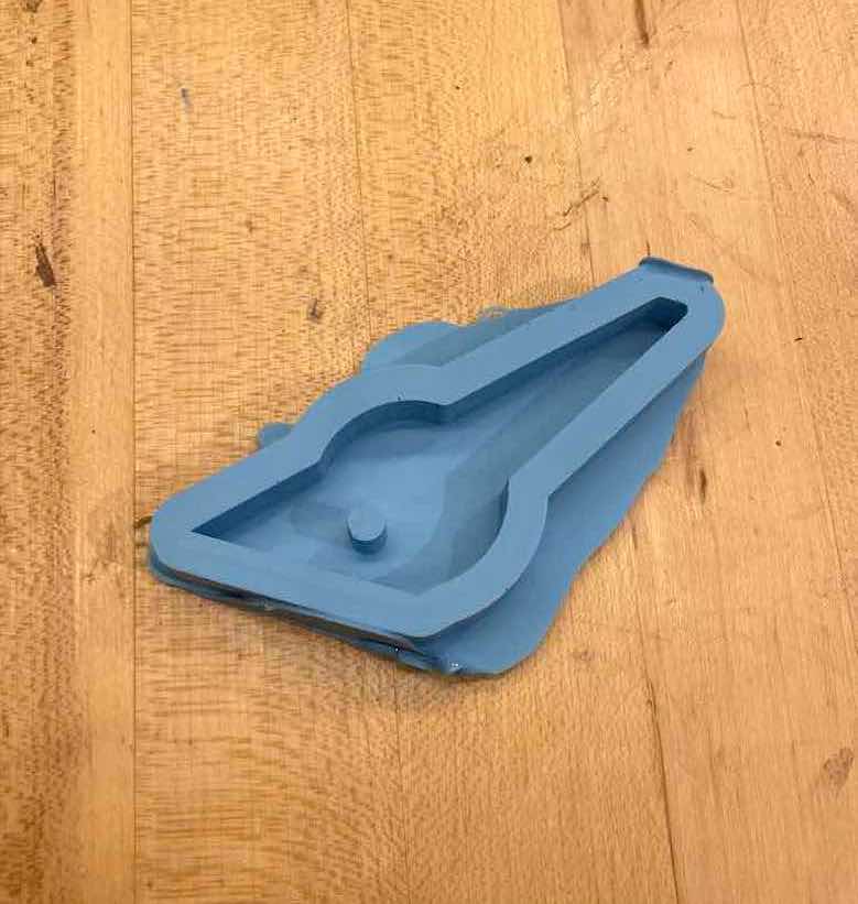
I cast the hook in bismuth and hydrocal.
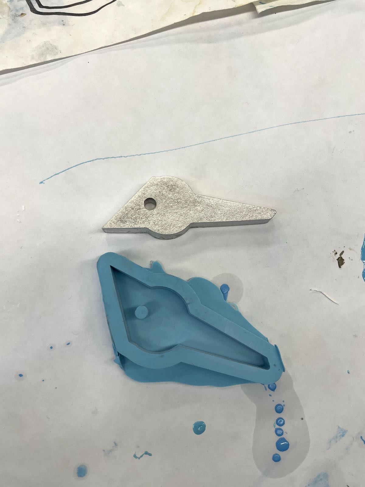
Overall I was satisfied with outcome of the cast. I'd like to try a two-part mold next time to eliminate the uneven surface finish on the side of the mold that is exposed to the air.
Week 08
Input Devices
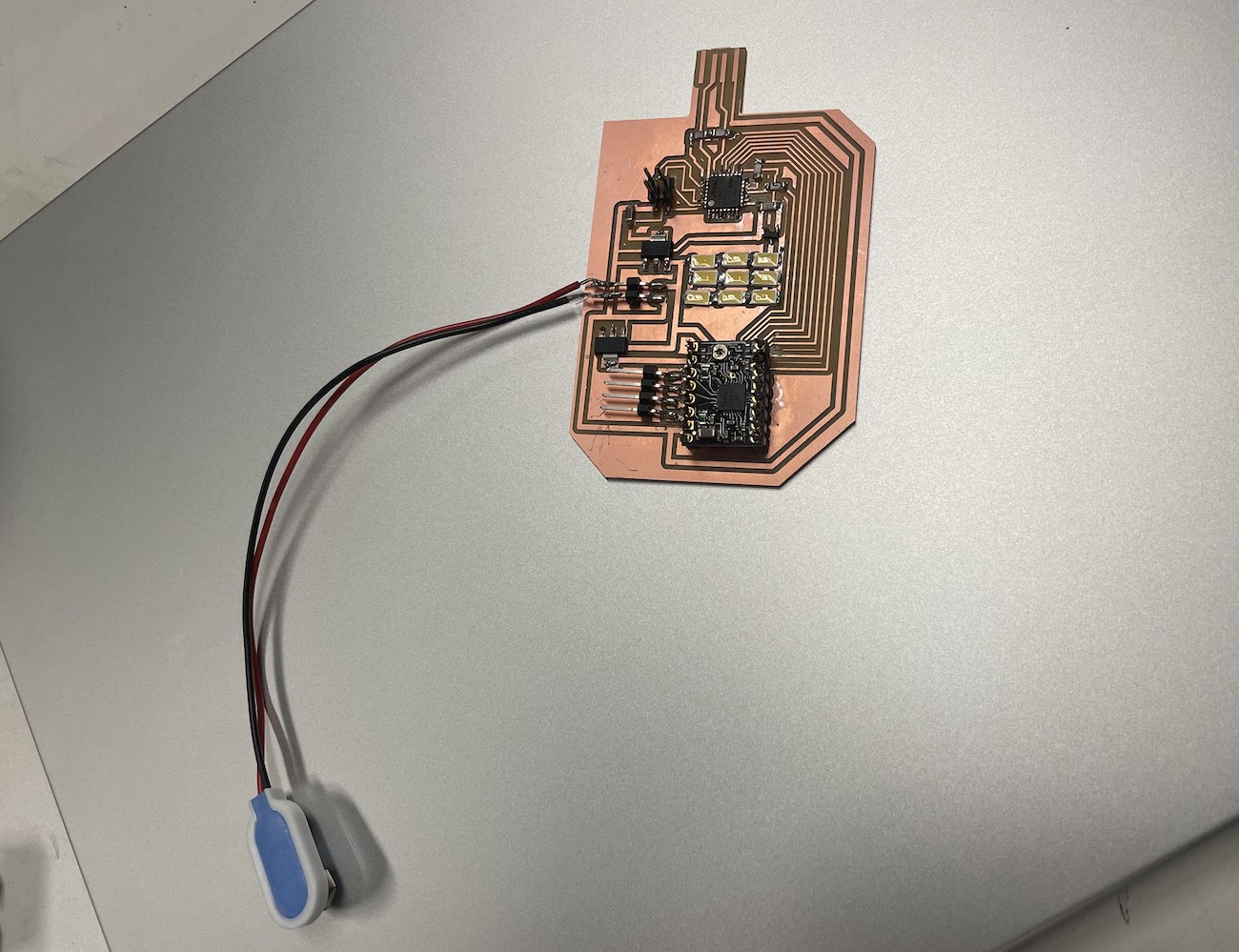
This week I attempted to read GPS and time data using the NEO-6M module. I wanted to integrate this input device into the "light clock" component of my final project in order to measure accurate time consistently over many weeks. The clock built into a microcontroller maintains fairly accurate time, but it would likely become out of sync after a few days. As oppossed to making a wifi-connected device, I wanted to solve this using UTC time data provided by this GPS module.
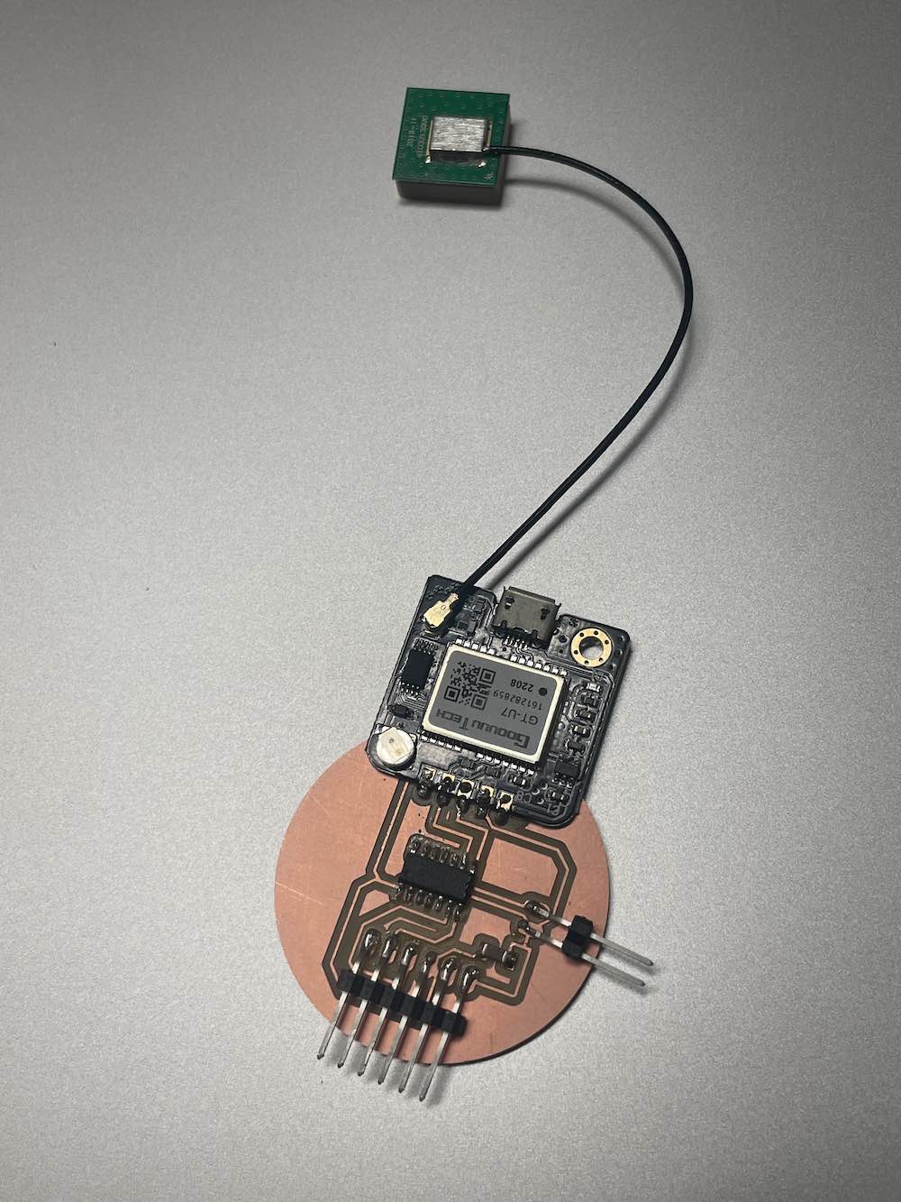
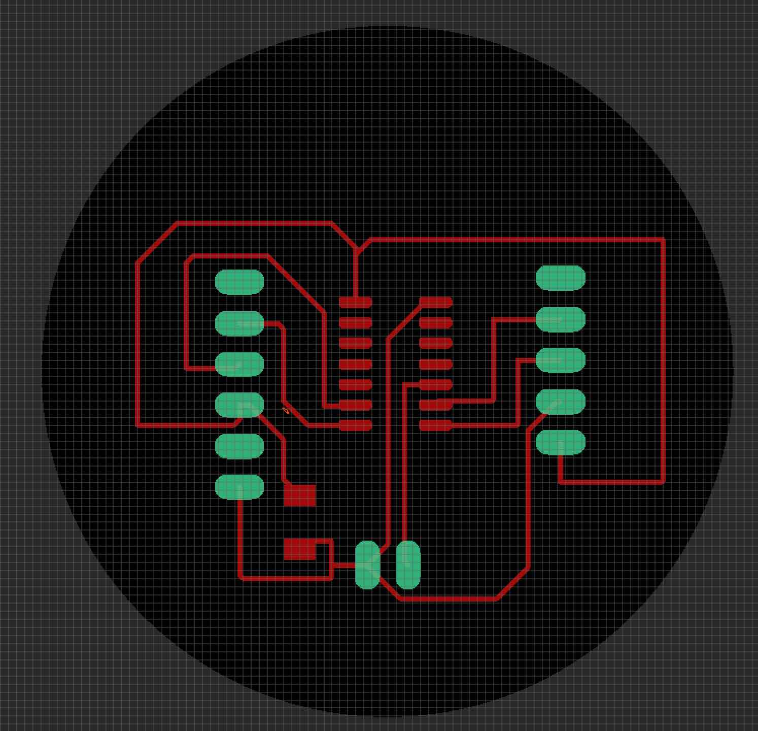
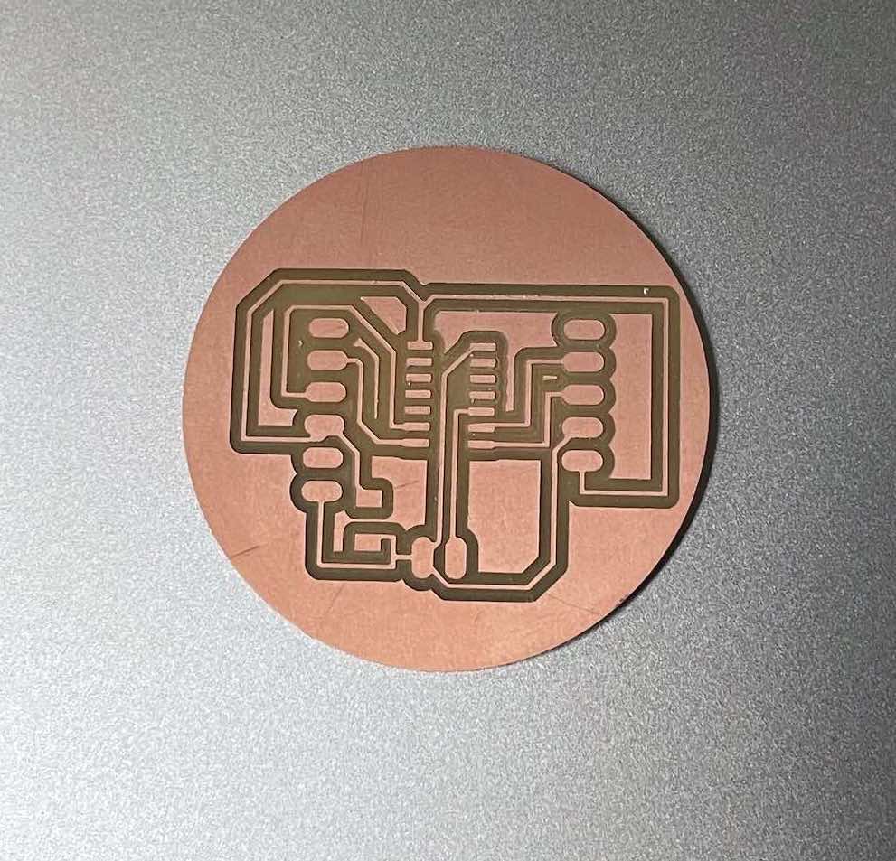
In order to increase the liklihood that my circuit worked, I wanted to keep PCB design simple/minimal to avoid potential soldering and hardware issues. I re-designed the circuit described in the example using Fusion/Eagle and routed the board by hand.
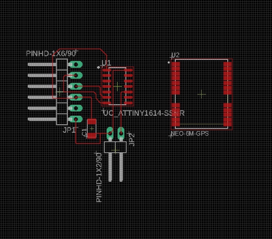
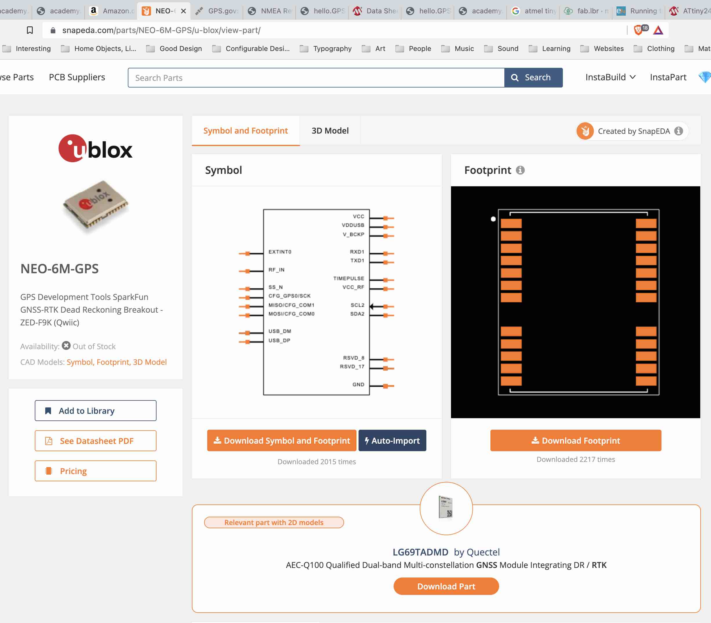
At first I began designing the PCB and attempted to wire up the connections directly to the NEO-6M-GPS module by downloading the footprint from SnapEDA and importing that footprint into Fusion. Soon afterwards, I realized that the packaged version of the chip that is sold on Amazon abstracts away all of the pins on the GPS component down to a simple 5-pin connector. I then changed my design to use a 5-pin connector.
After receiving my GPS component in the mail, I soldered all of the components onto my board. I ordered the GPS unit on Friday 11/4, and it was suppossed to be delivered on Saturday 11/5. Unfortunately the package was marked as delivered on Amazon but never arrived, so I had to place a new order on Sunday which was delivered on Tuesday afternoon 11/8.
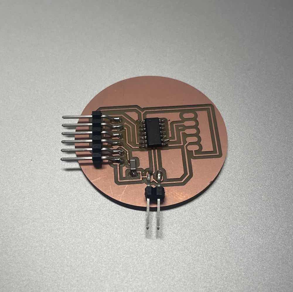
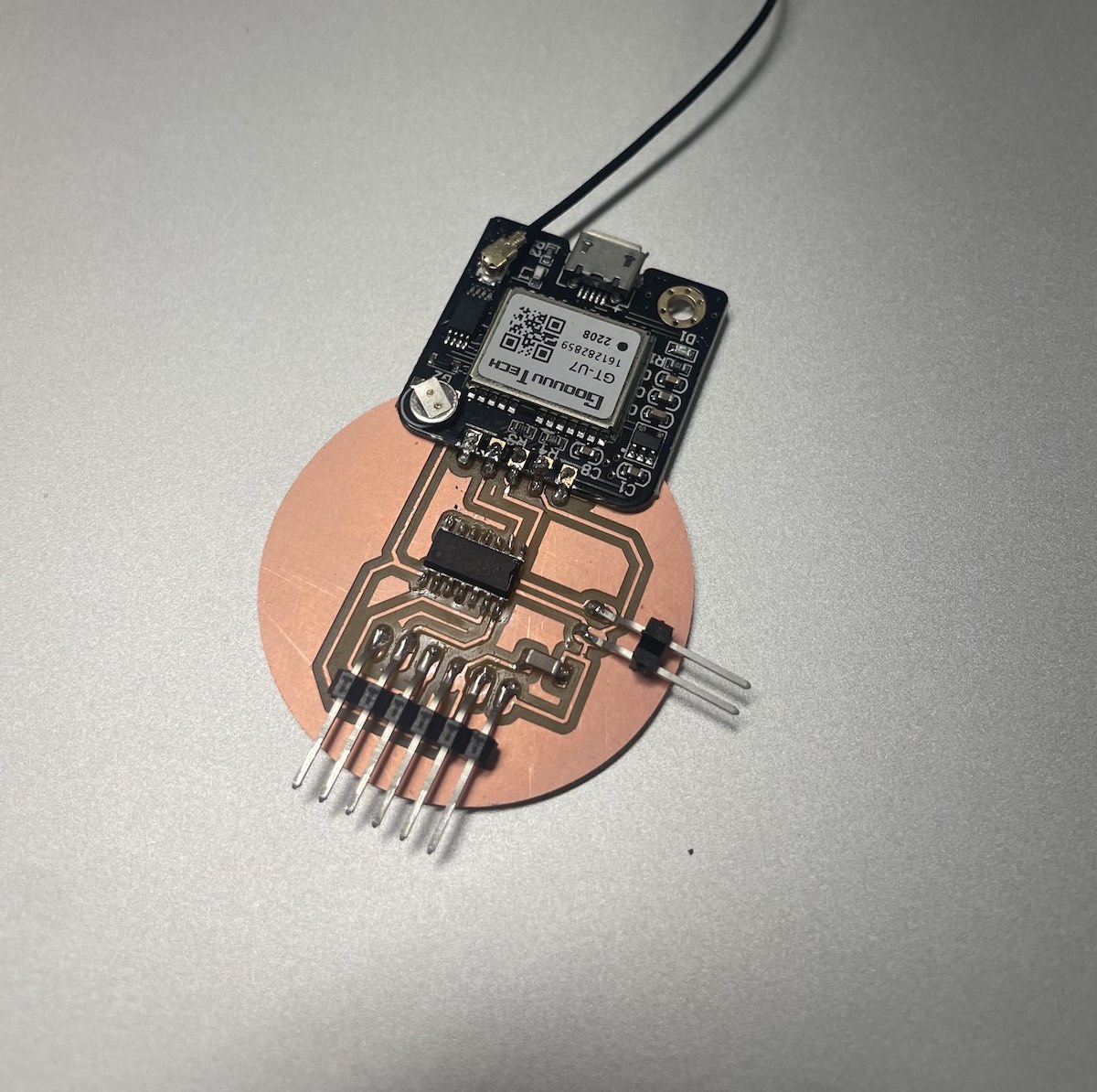
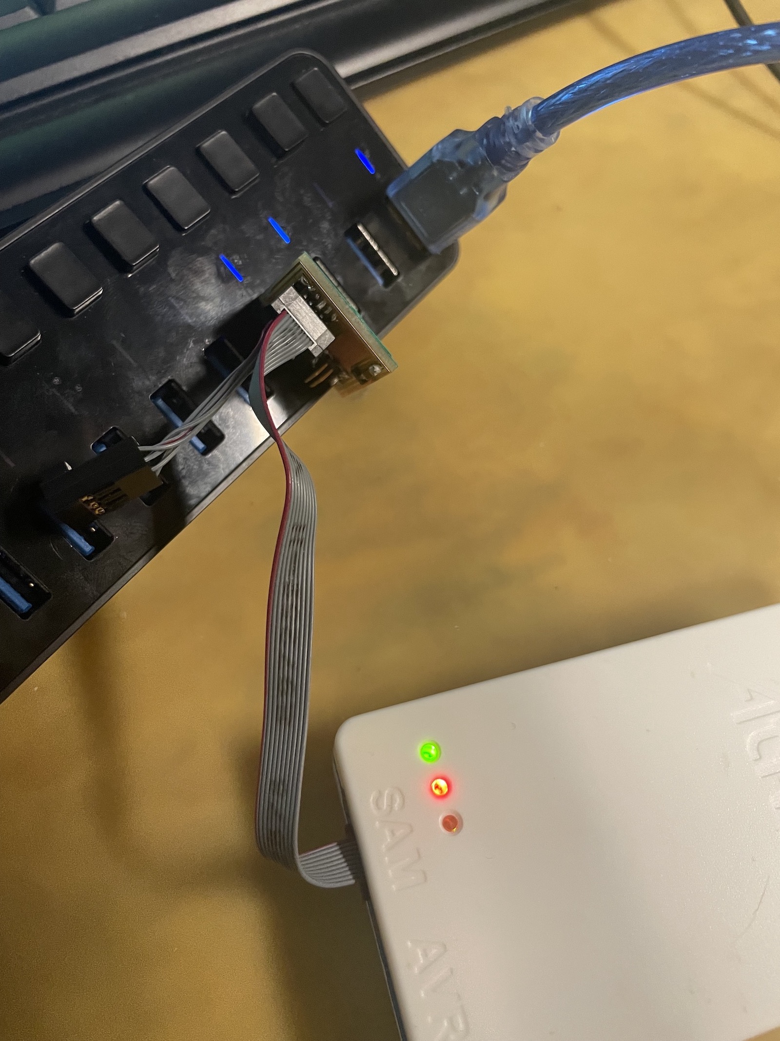
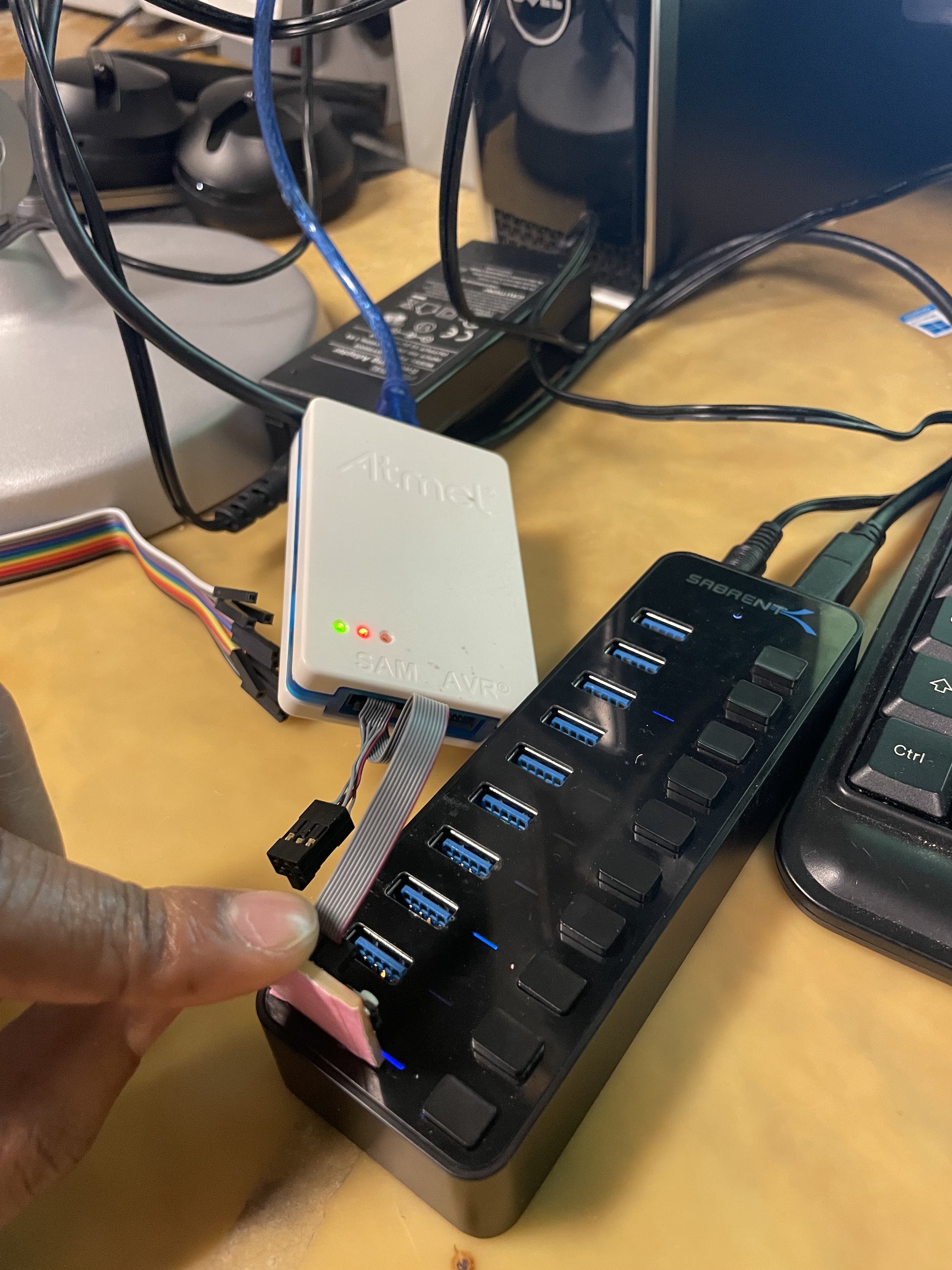
The first mistake I made with this board was not including a USB connection. This meant that I needed to use the UDPI and ground pins at the bottom of the board to load the bootloader onto the microcontroller. Thankfully Quentin lent me a programmar that enabled me to communicate with the microntroller using only these two pins, while powering the board using the 6-pin connected on the left of my board. The programmer he lent me is shown below plugged into a laptop, and connected to my board using two separate female wires. My board is also connected to the laptop via the 6-pin connector.
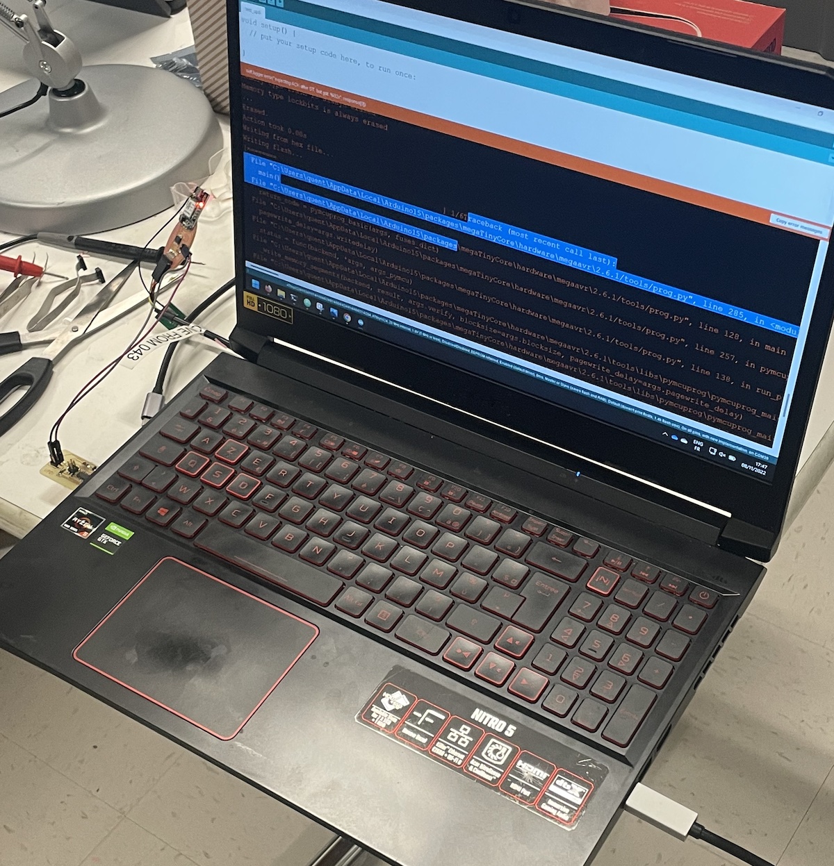
The board I created uses the ATTINY1624 microcontroller which communicates using the UDPI protocol as oppossed to SWD/JTAG which the SAMD11's use. This proved to be a problem as I began to program the board on my M1 macbook pro. I needed to download and install the megaTinyCore board package to write code for this controller. With the help of Quentin I installed this package in Arduino and tried to test a helloWorld program.
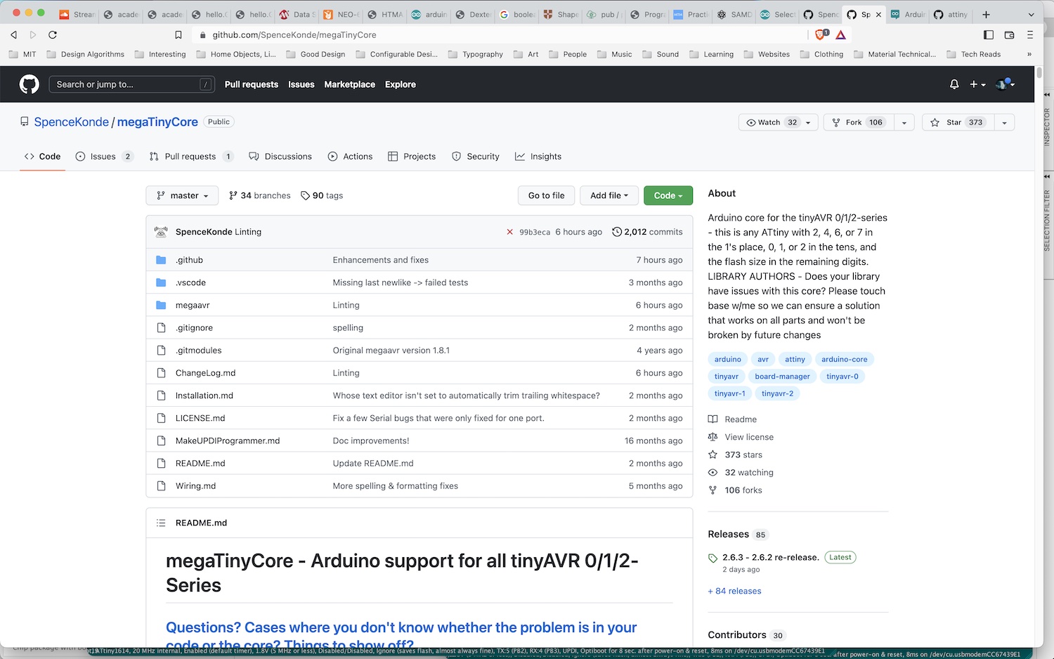
The latest versions of megaTinyCore did not work on the M1 macbook arm chips so I needed to downgrade to the latest working version of megaTinyCore for M1 macs (2.6.1). I selected the ATTINY1624 for the board and chip variables in Arduino and ensured that I was using the port corresponding with the programmer. Quentin tested the helloworld program on his laptop and was able to get it to work. We used the same settings on my laptop and I was consistently met with "UDPI initialisation failed". We chose programmers that use different clock speeds to attempt to fix the issue, but unfortunately we couldn't find a solution on my machine.
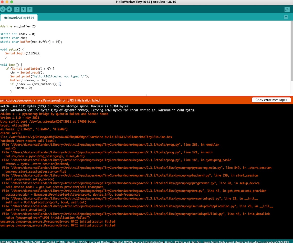
When I create this board again for my final project, I plan to include a USB connection on the PCB to eliminate the need for an external programmer. I also plan to design the board for the SAMD21 chip to eliminate the issue I experienced using megaTinyCore in Arduino on my M1 macbook laptop, which seems to cause problems for many different coding toolkits that I use.
Week 09
Output Devices
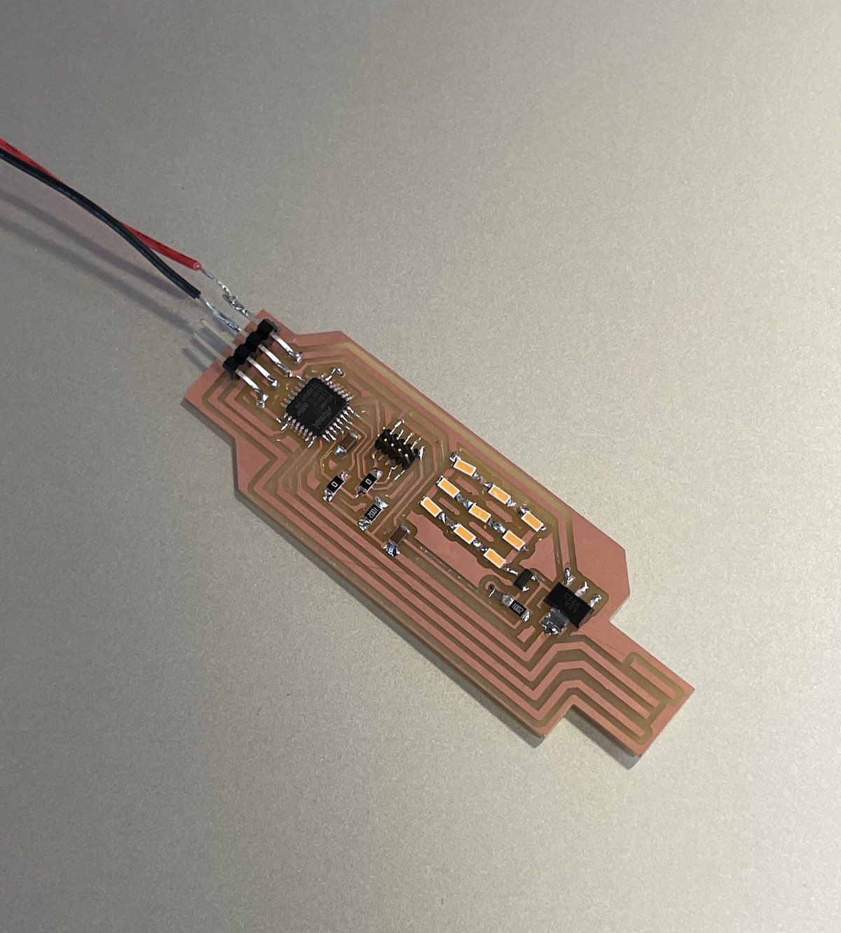
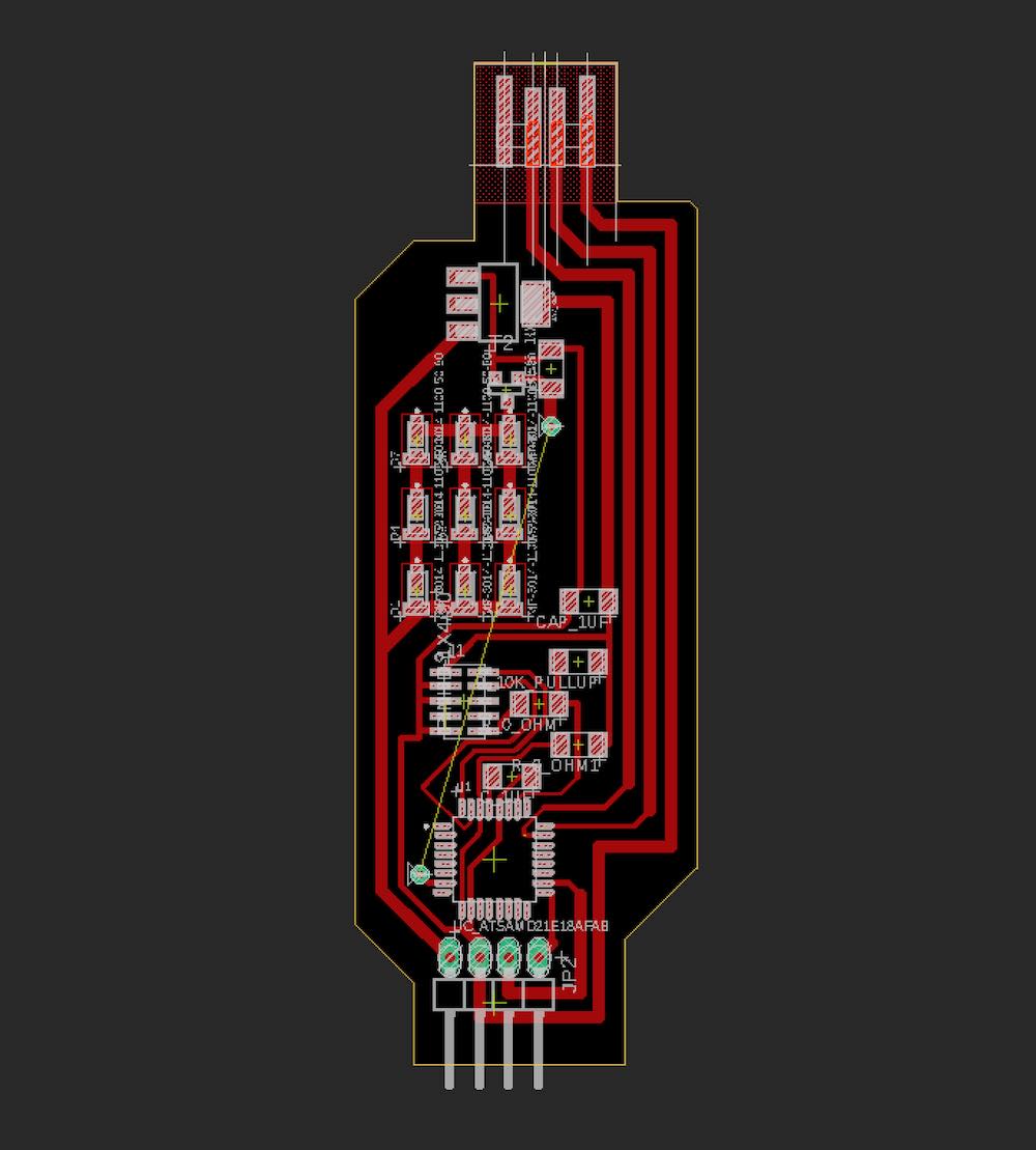
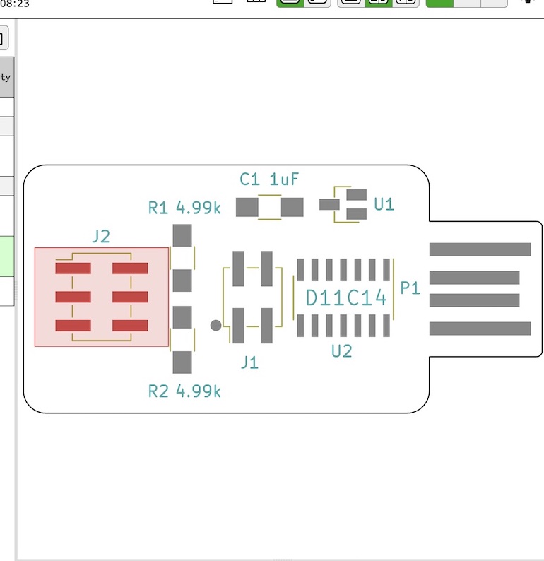
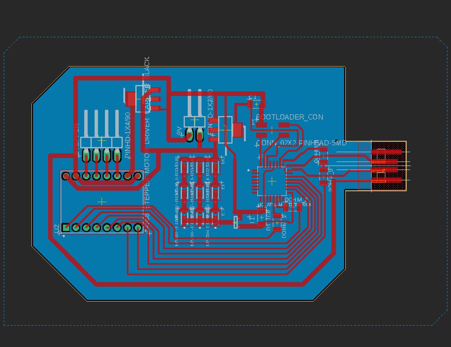
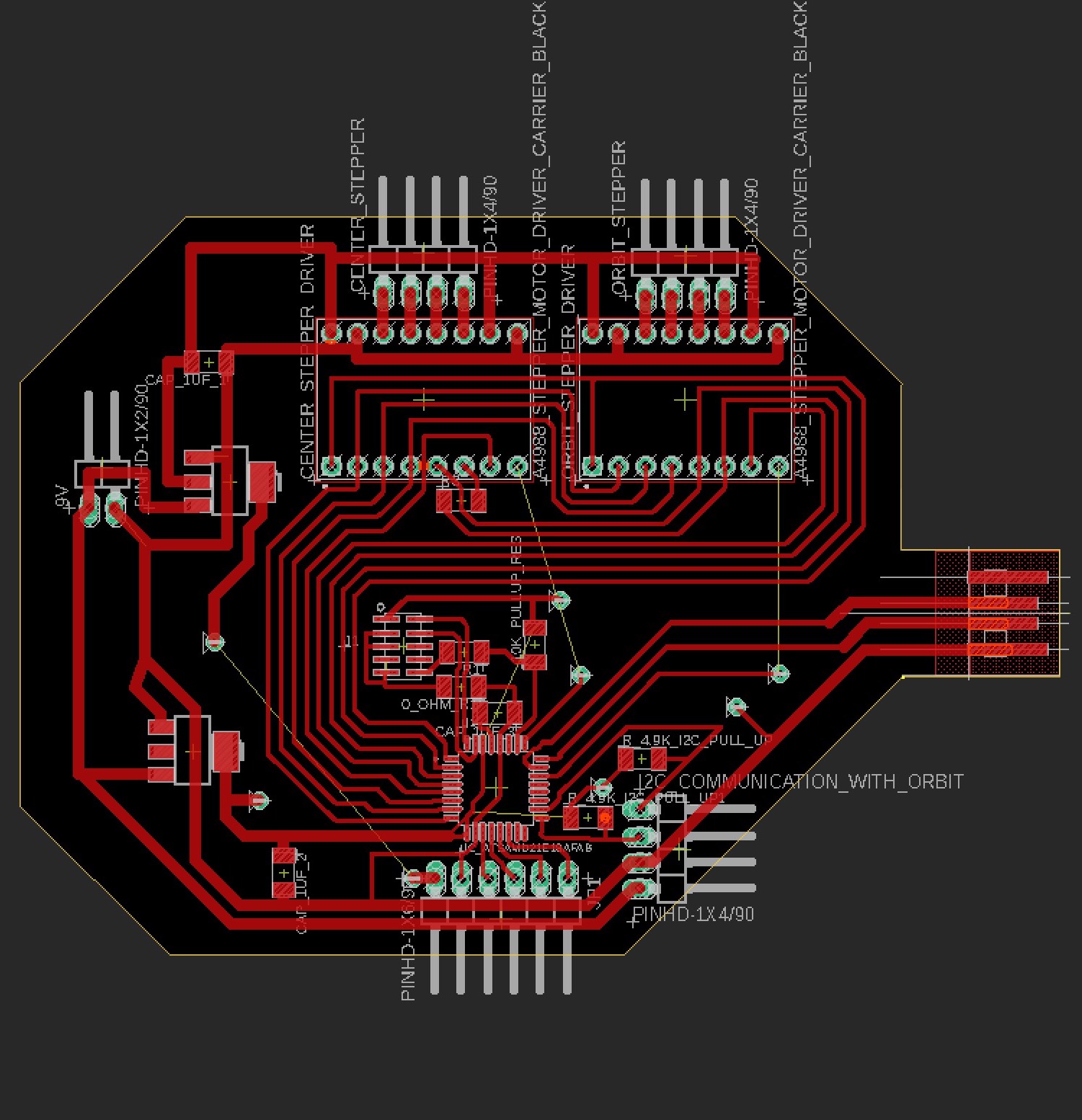
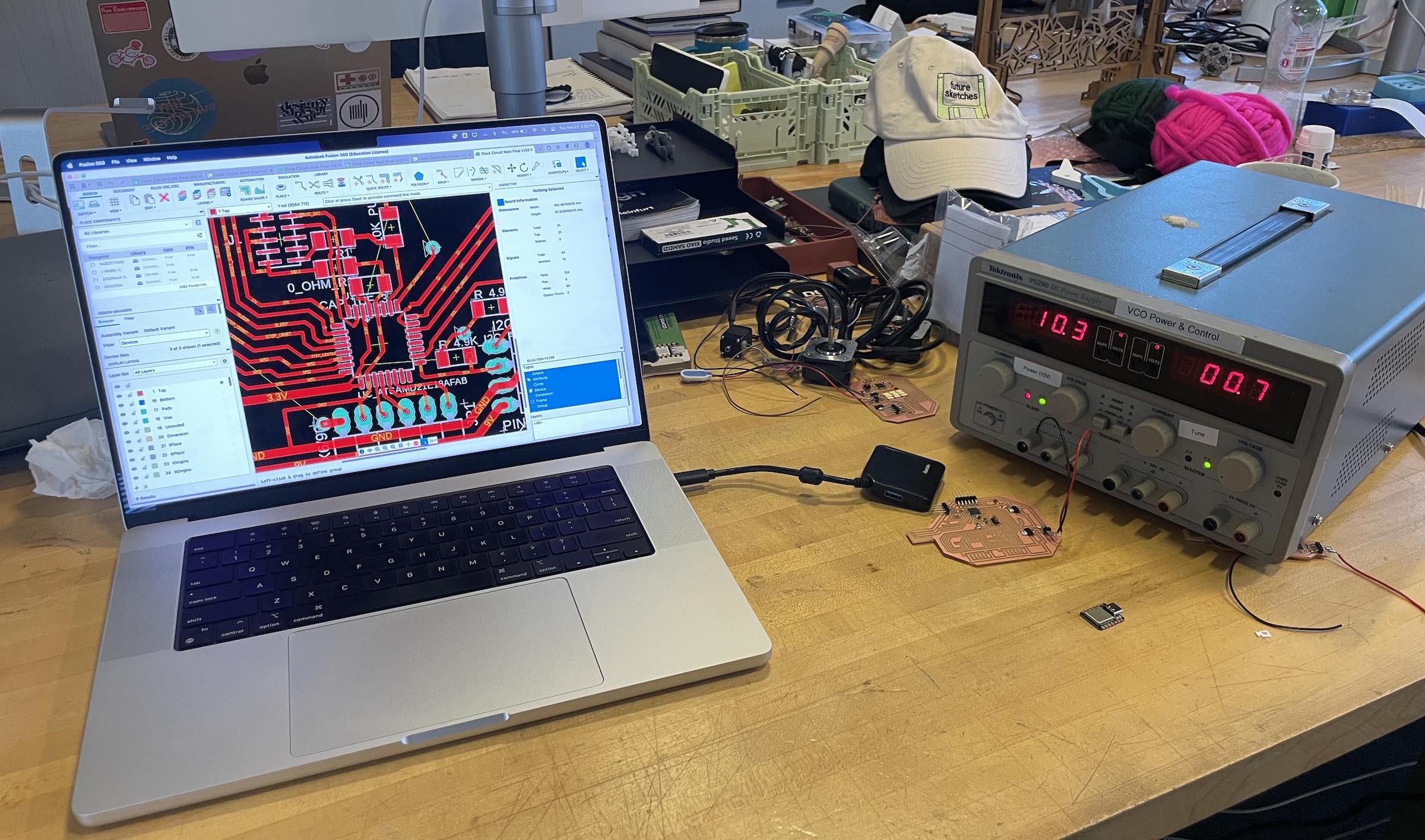
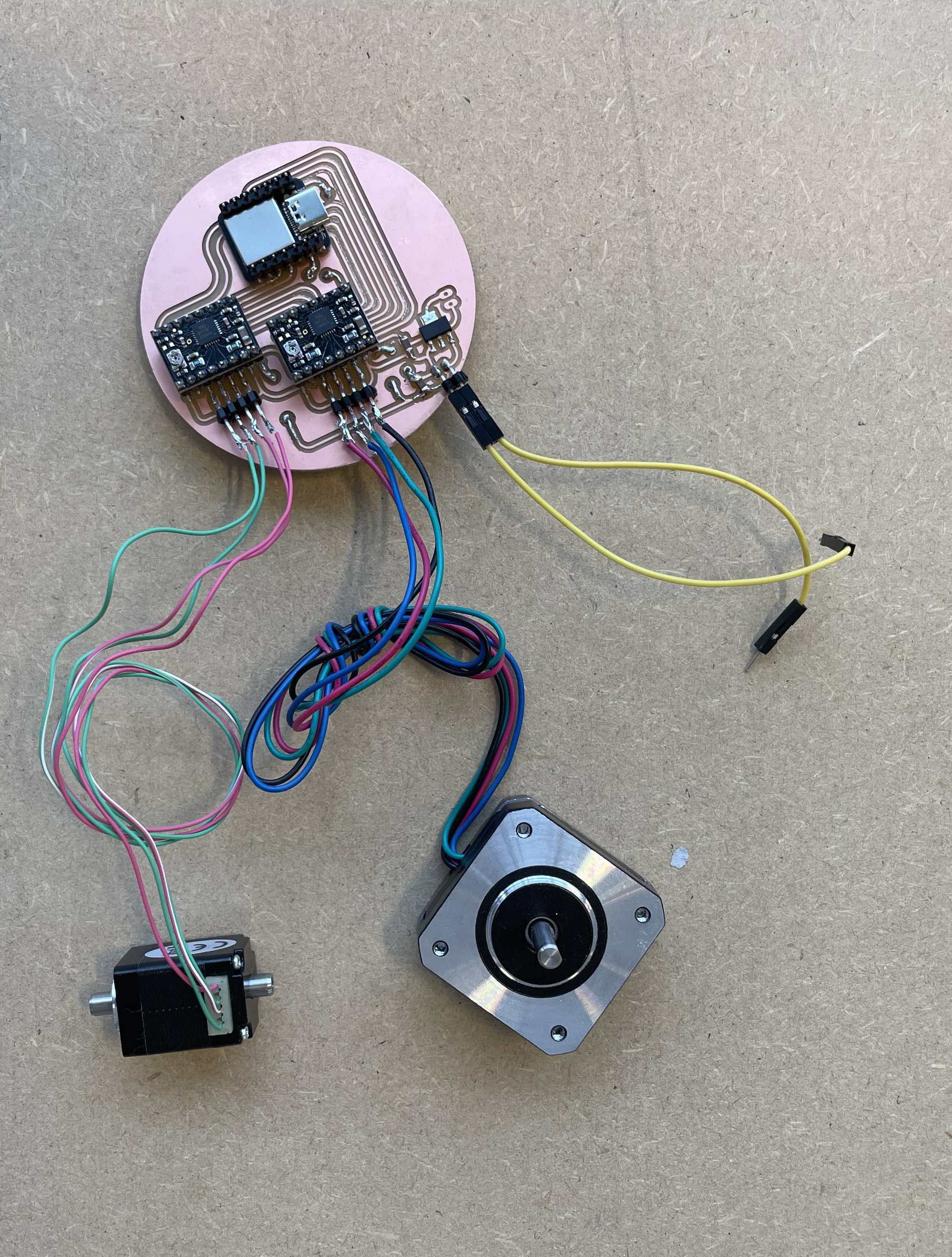
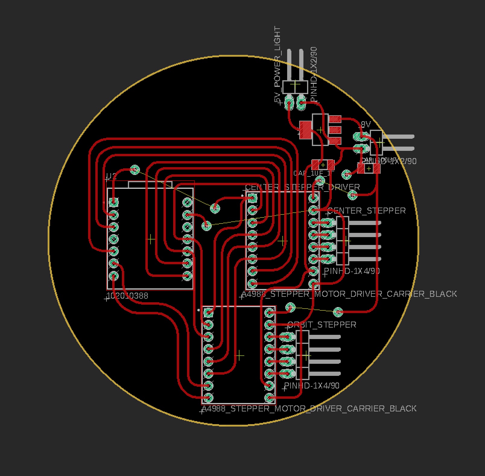
This week I began designing a prototype for the circuit I'll use in my final project. The circuit contains 9 very bright drop diodes, a stepper motor driver, and pins for a stepper motor, all powered by a 9V battery.
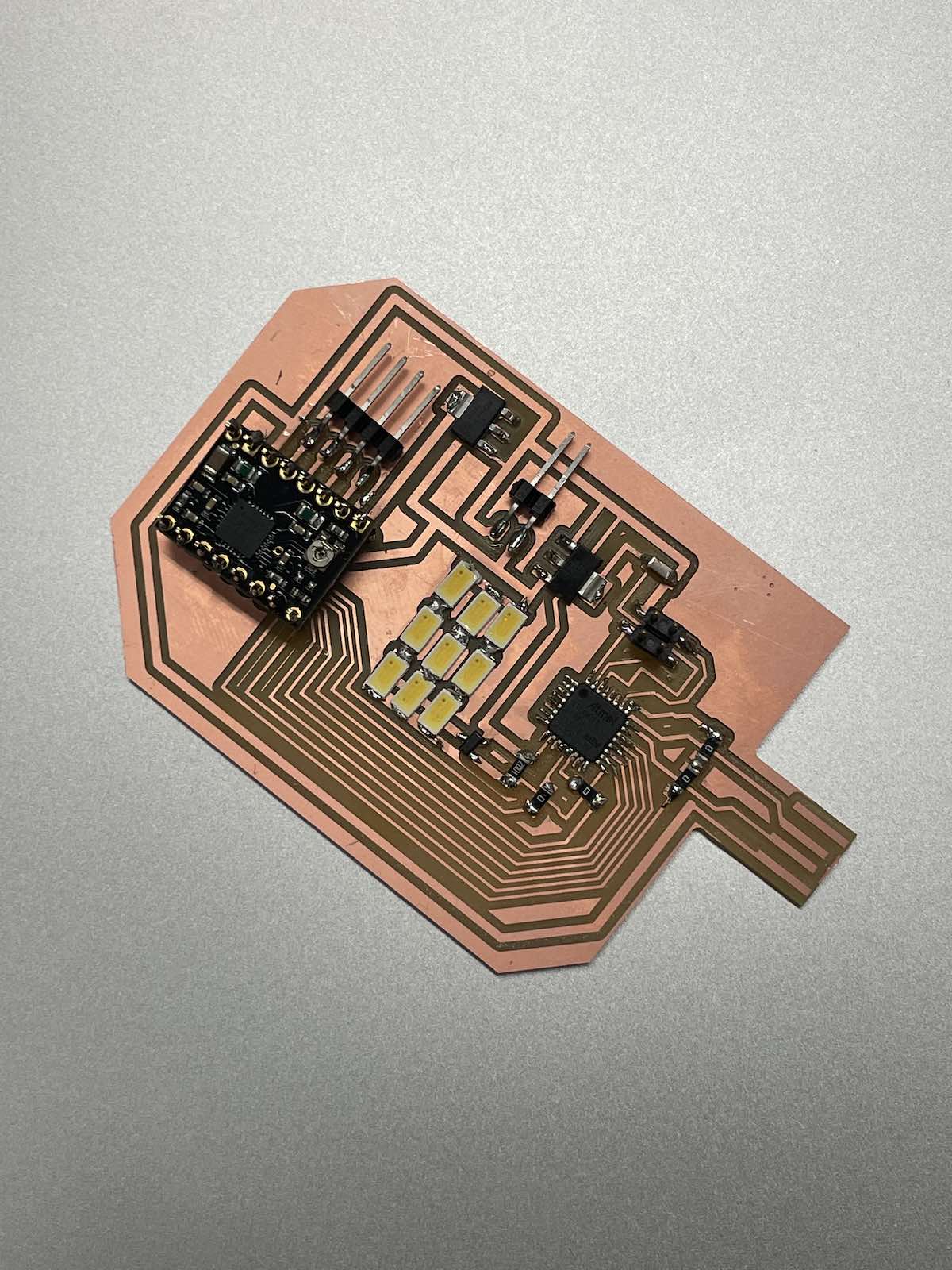
At first I wanted to use the DRV8428 stepper motor driver to control the stepper, however they were out of stock on digikey due to supply chain shortages. I then began to design my circuit by attempting to use two H-bridges to control the stepper motor.
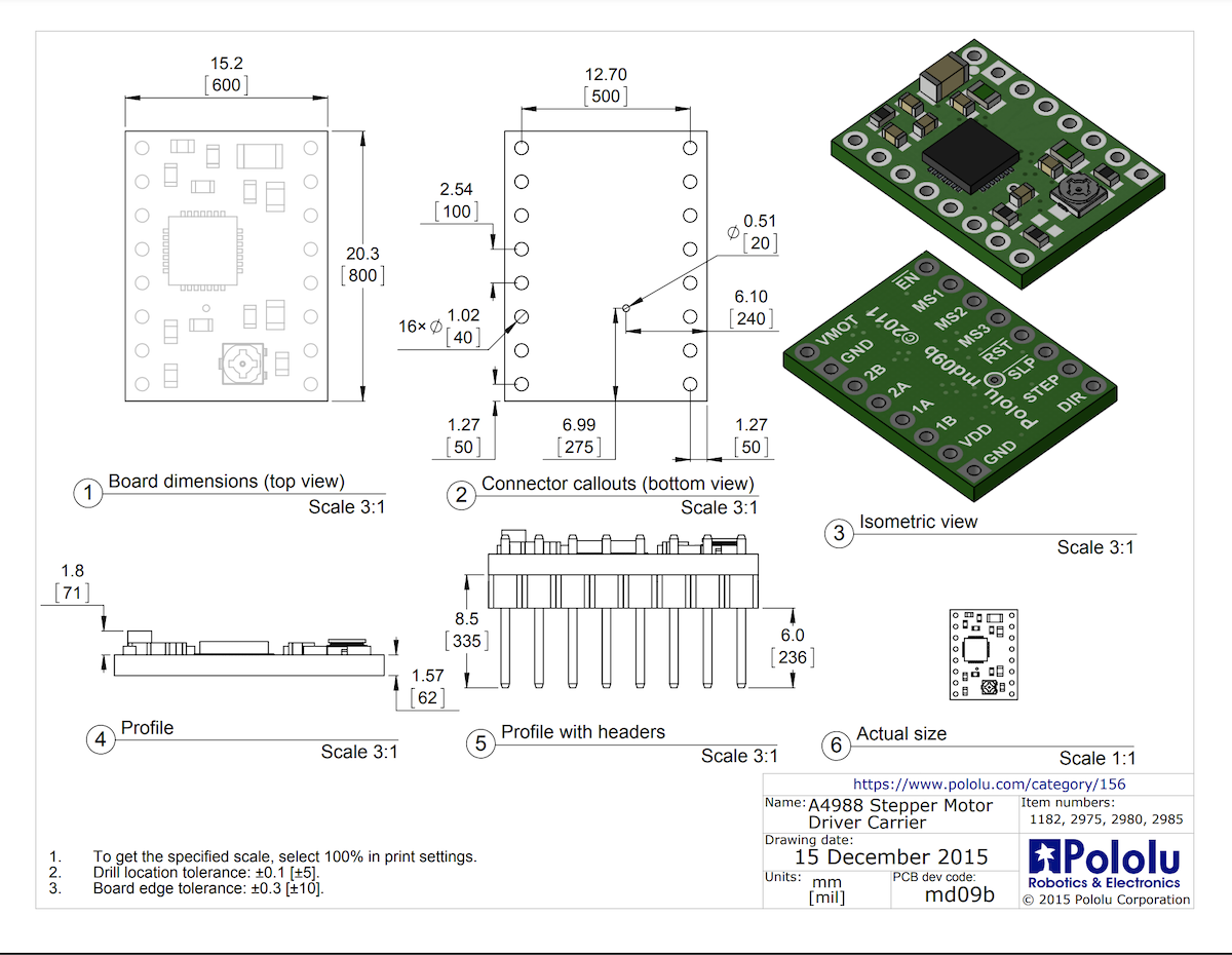
Halfway through this process, thankfully one of the TA's recommended that I use a different stepper driver that is readily available, so I moved forward with the Popolu A4988 stepper motor driver and ordered a few more for my final project.
I took time to carefully read the datasheet for this driver and connected it up to my SAMD21. I know that I'll need to use the microstepping feature this driver provides. I will also need to control multiple stepper motors as part of my final project, so I noted with signals I could split out and duplicate for both motors, and which would need to be controlled independently.
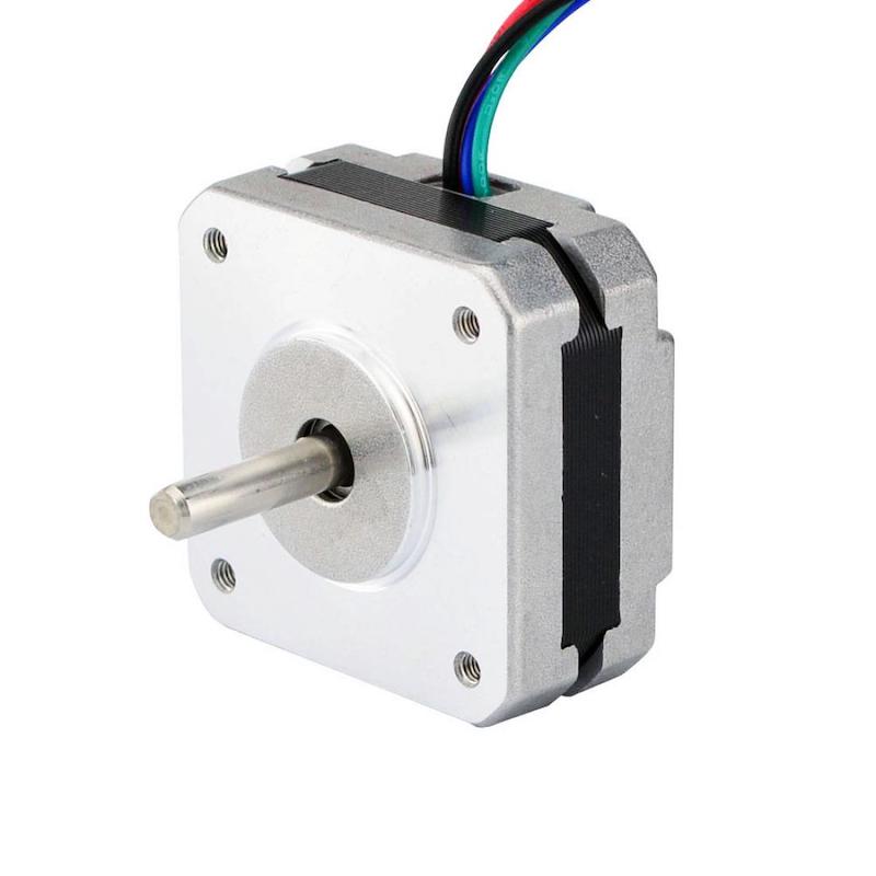
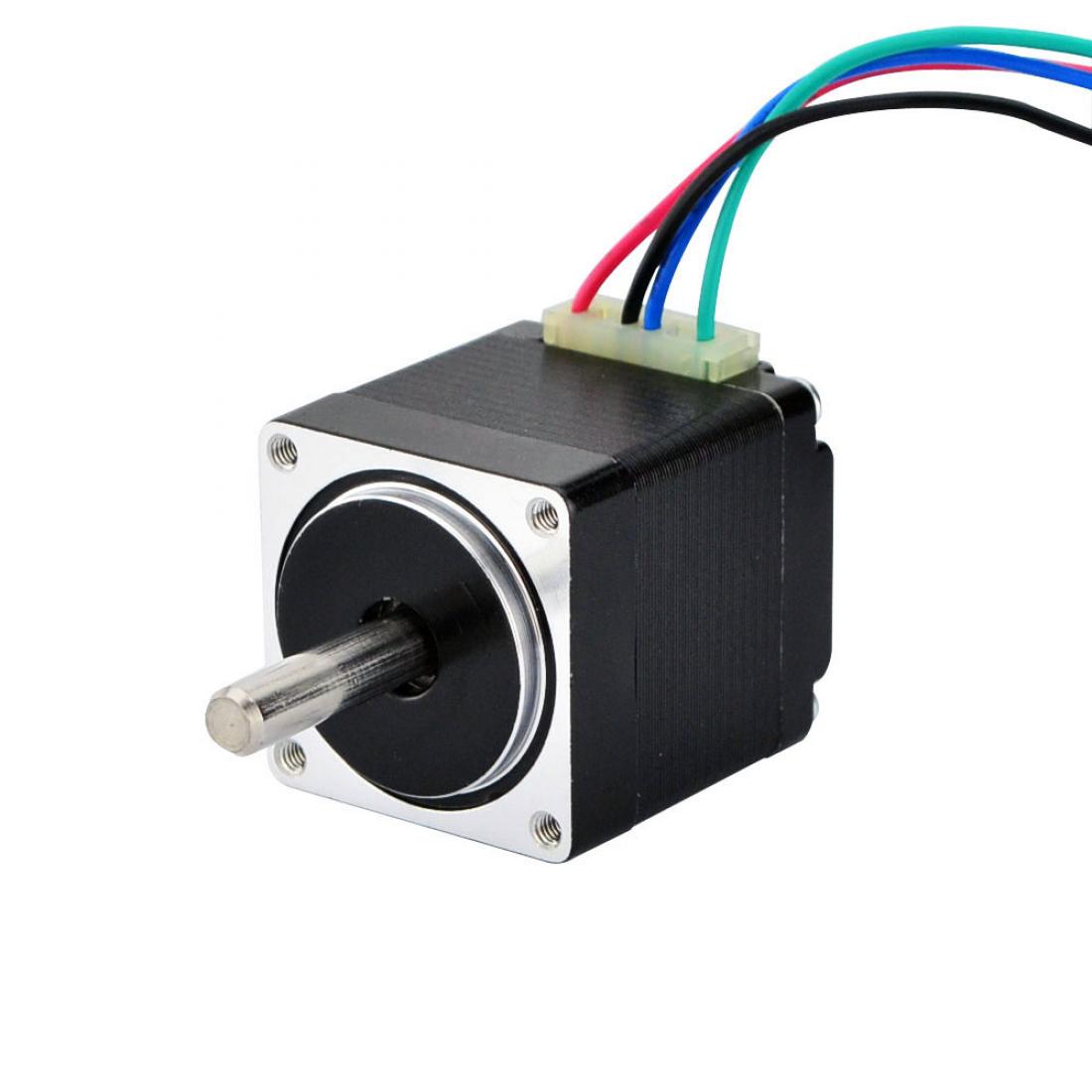
I also researched and purchased four different stepper motors made by Nema that satisfied the size and estimated torque/power requirements for my final project. I plan to make designs for both a normal rectangular-shaped stepper motor as well as a pancake stepper motor. I designed my circuit to account for the voltage requirements for these motors.
I cut and soldered the final design for my circuit and attached a 9V battery. When I plugged the four pins into the Atmel ICE, the board was recognized by the USB hub.
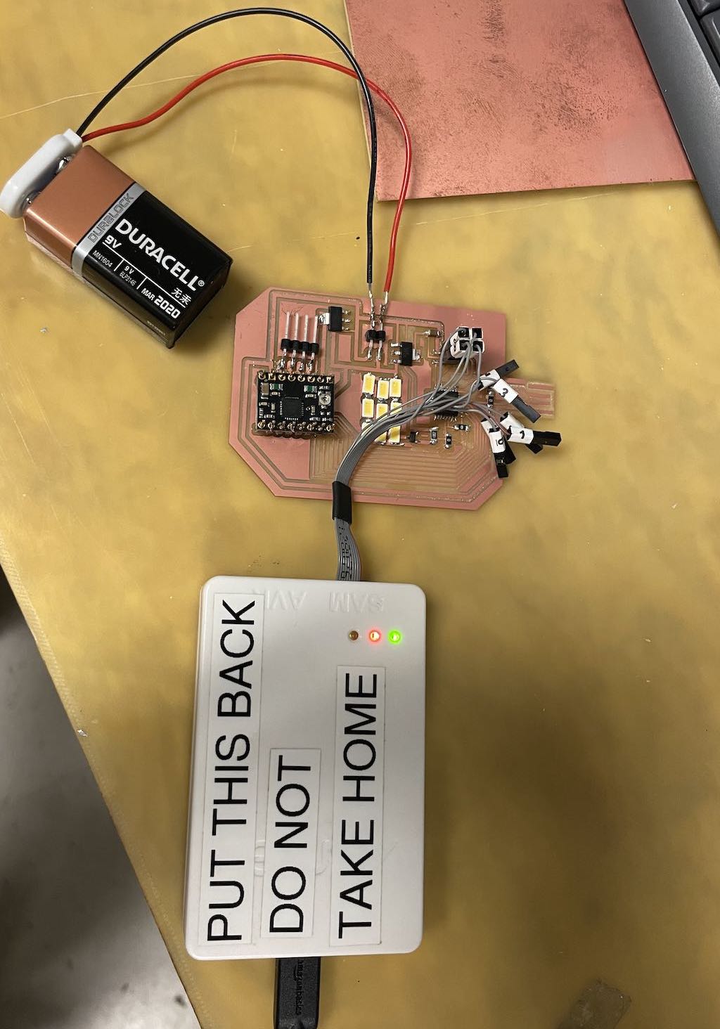
Ultimately after further testing, I realized that the board would not work proprely due to improperly routing the debug header for the SAMD21. I later redesigned the board, removing the LEDs and simplifying the routing to control only two pololu stepper drivers. I also decided to use a pre-housed SAMD21 with USB-C connector to simplify the soldering and debugging process.
Eventually, after an extensive debugging process, I was able to run both stepper motors using this board.
Week 10
Networking
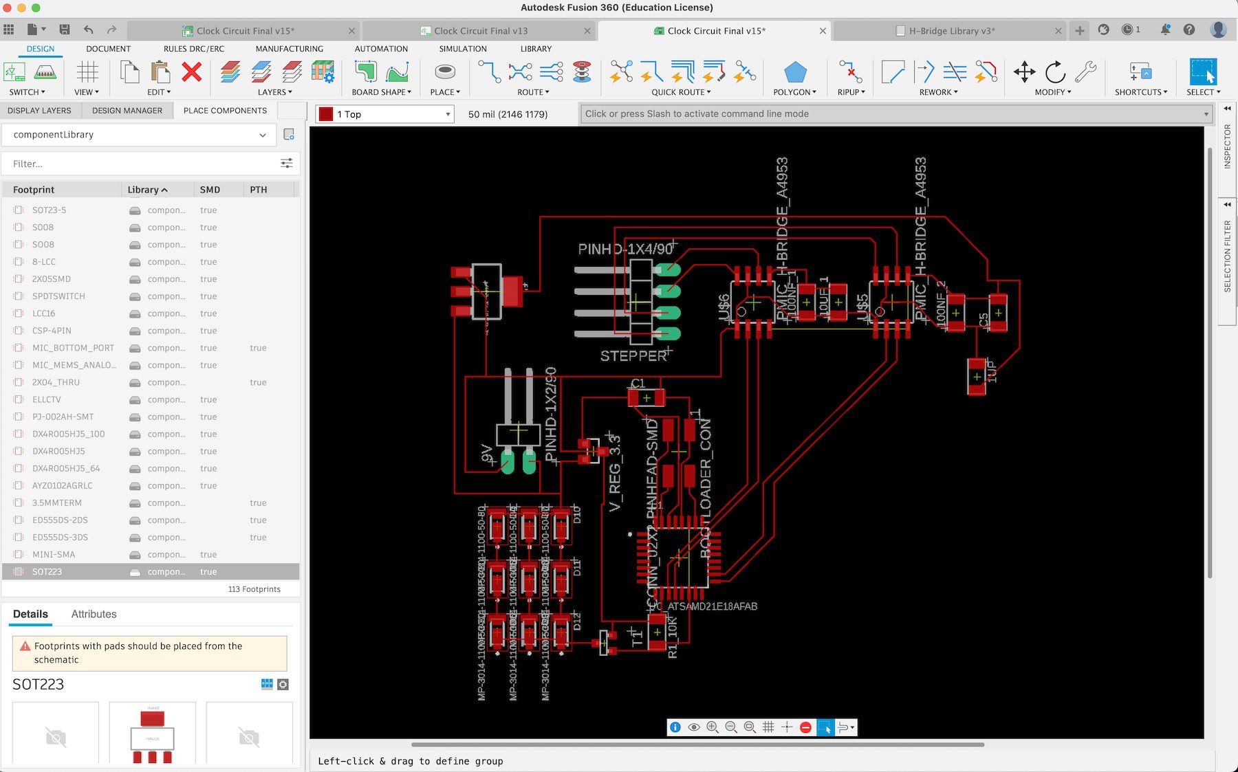
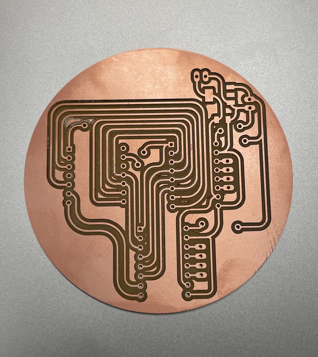
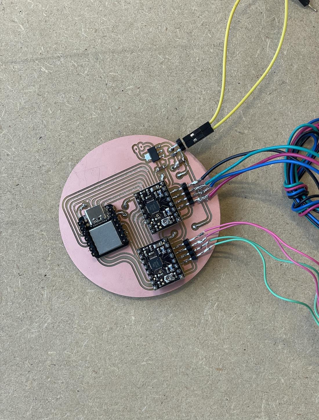
My goal this week was to network between the two PCBs that I need for the light clock component of my final project.
The light clock requires one main PCB that will control two stepper motors using dedicated stepper drivers. The other peripheral PCB will house the array of high intensity diodes that create the light beam. I wanted to communicate between the boards using the I2C pins on the SAMD21.
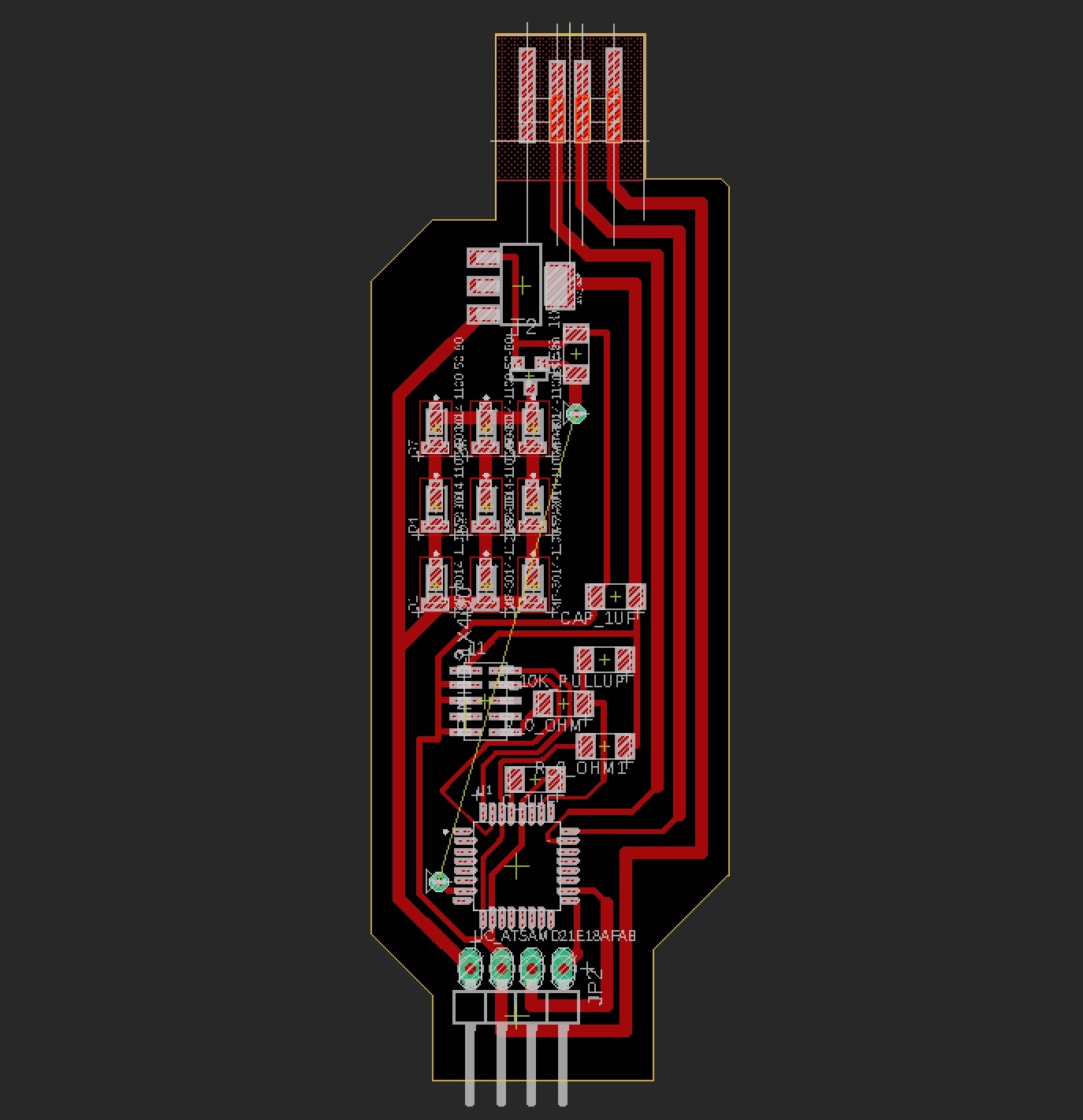
I designed and manfuctured three different versions of these PCBs this week, debugging electronics design issues after each iteration. I had issues bootloading the SAMD21 using only 4 pins, so I later switched to the standard 10-pin header.
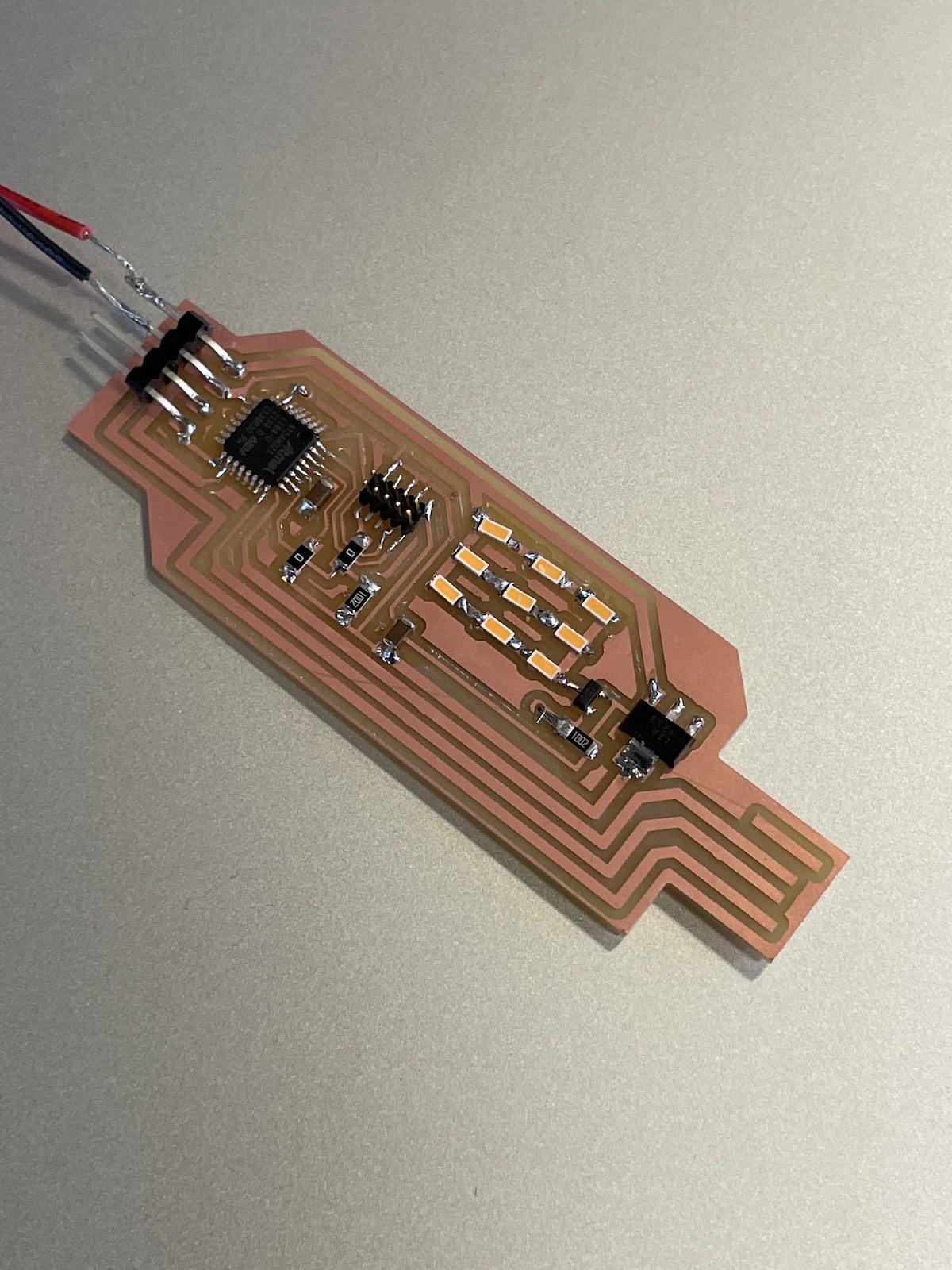
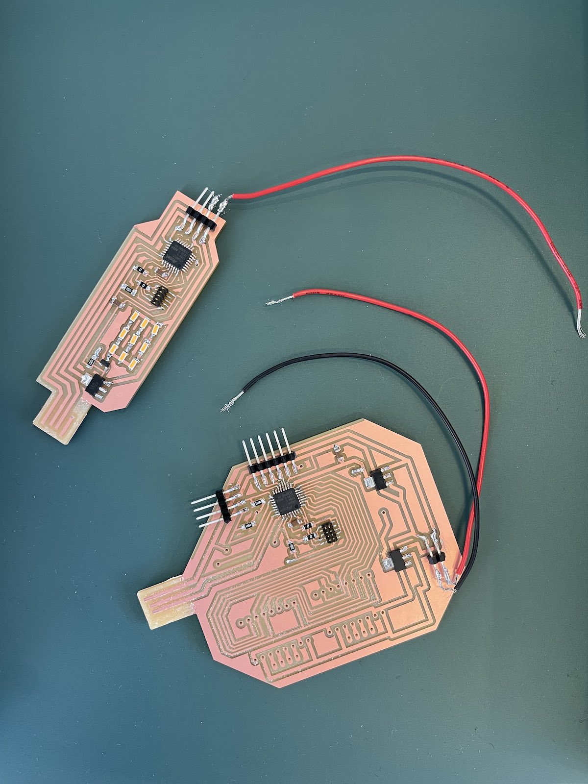
My final project will ultimately be powered from an external power source, so I wanted to test programming these boards using a power source.
I successfully ran a hello world program on the board, but didn't get to complete the networking implementation. I plan to complete this for the final project.
Week 11
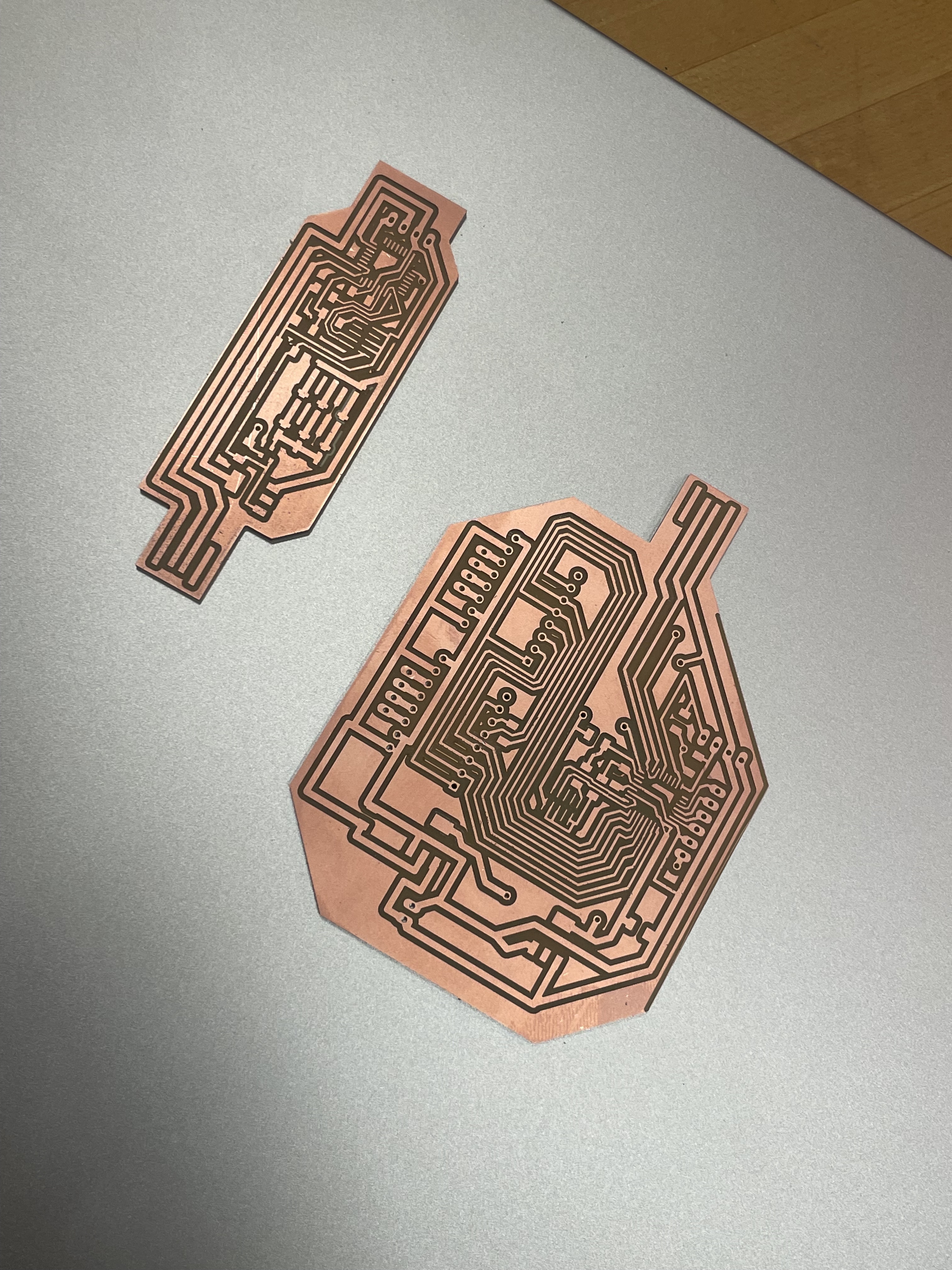
Interface & Application Programming
This week in addition to experimenting with interface and application programming, I re-cut, soldered and programmed the main board for my final project. I also began preliminary physical design in Fusion.
Since I focused most of my efforts on my final project board, I interpretted the application and programming assignment for the week rather loosely due to time constraints. I wrote an application that "interfaces a user with an input or output device" via a webcam that tracks the position of the device over a planar object (using Python/OpenCV) and maps it's location within a Three.js scene running in the browser.
If I have more time I'd aim to implement better object tracking that also has the ability to account for an objects orientation. I also began thinking about collaborative design software that would allow a user to design three-dimensional objects using a physical interface.
Week 13
Wildcard Week (Zund Large Format Cutting, Waterjet, & Fiber Laser)
This week I used the Zund large format cutting machine, the waterjet, and the fablight fiber laser to manufacture parts for my final project.
Zund Large Format Cutting
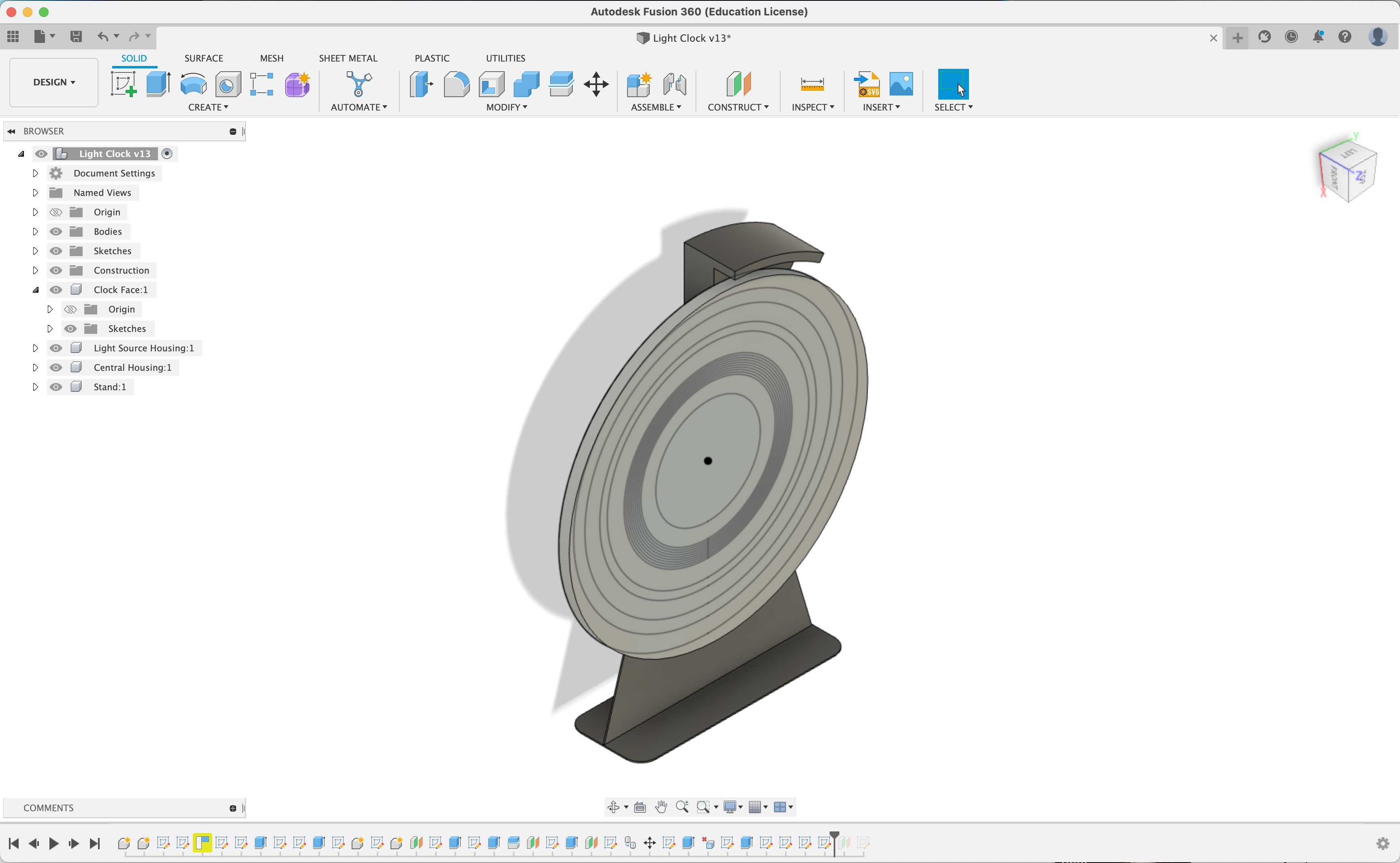
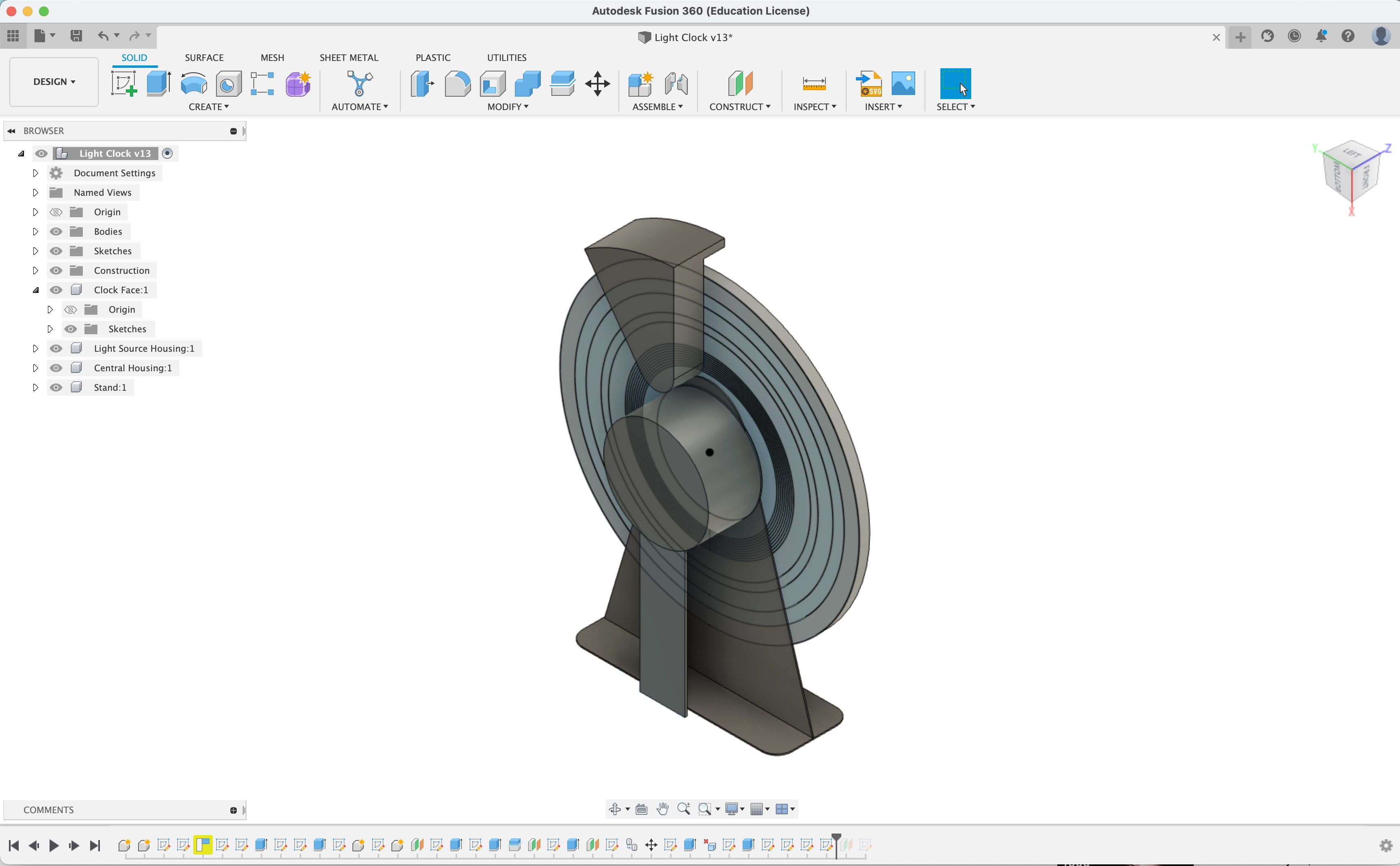
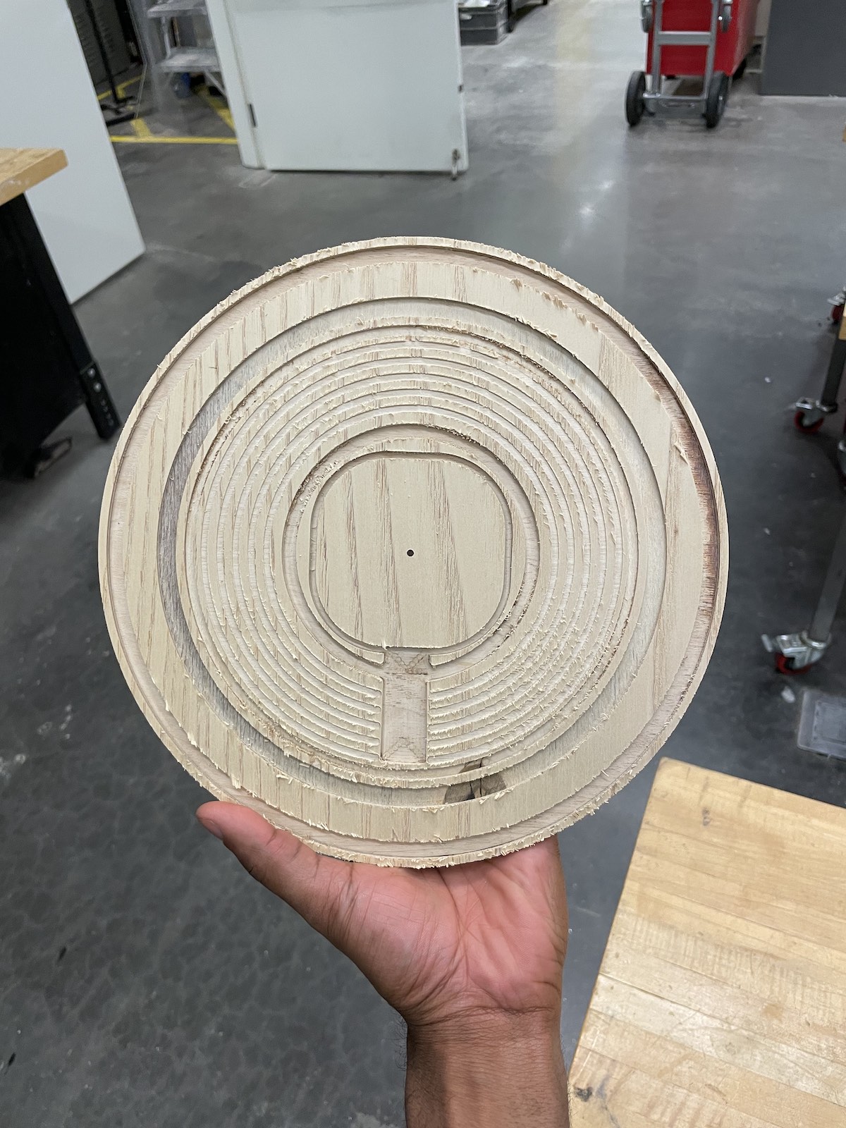
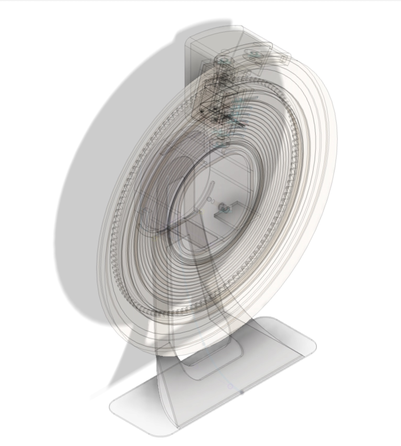
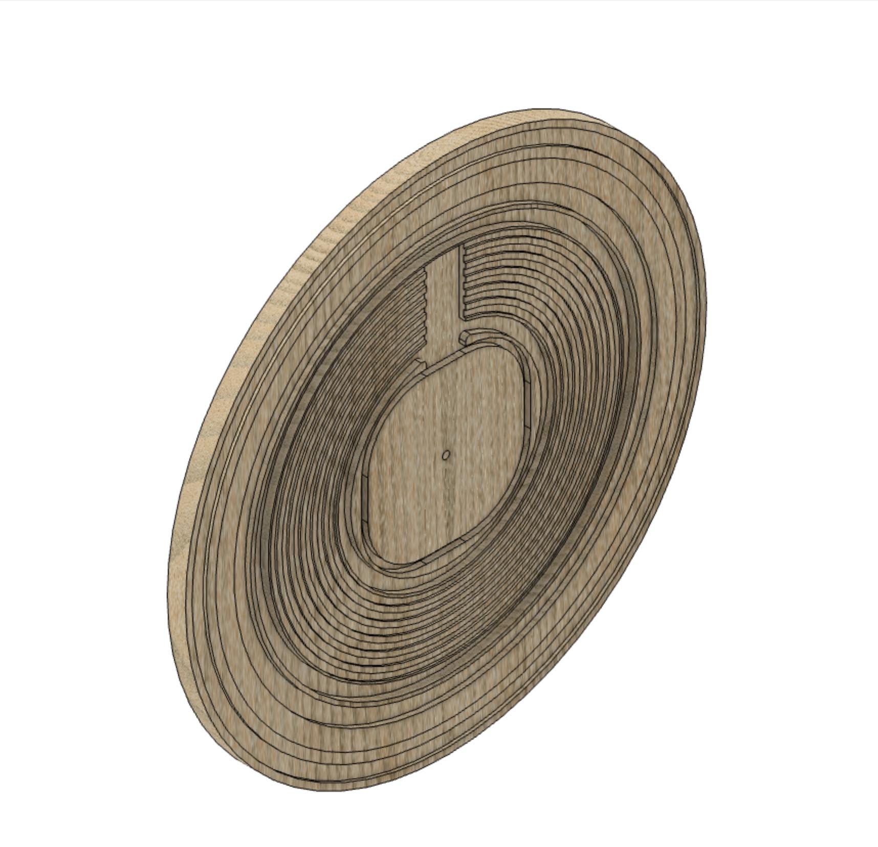
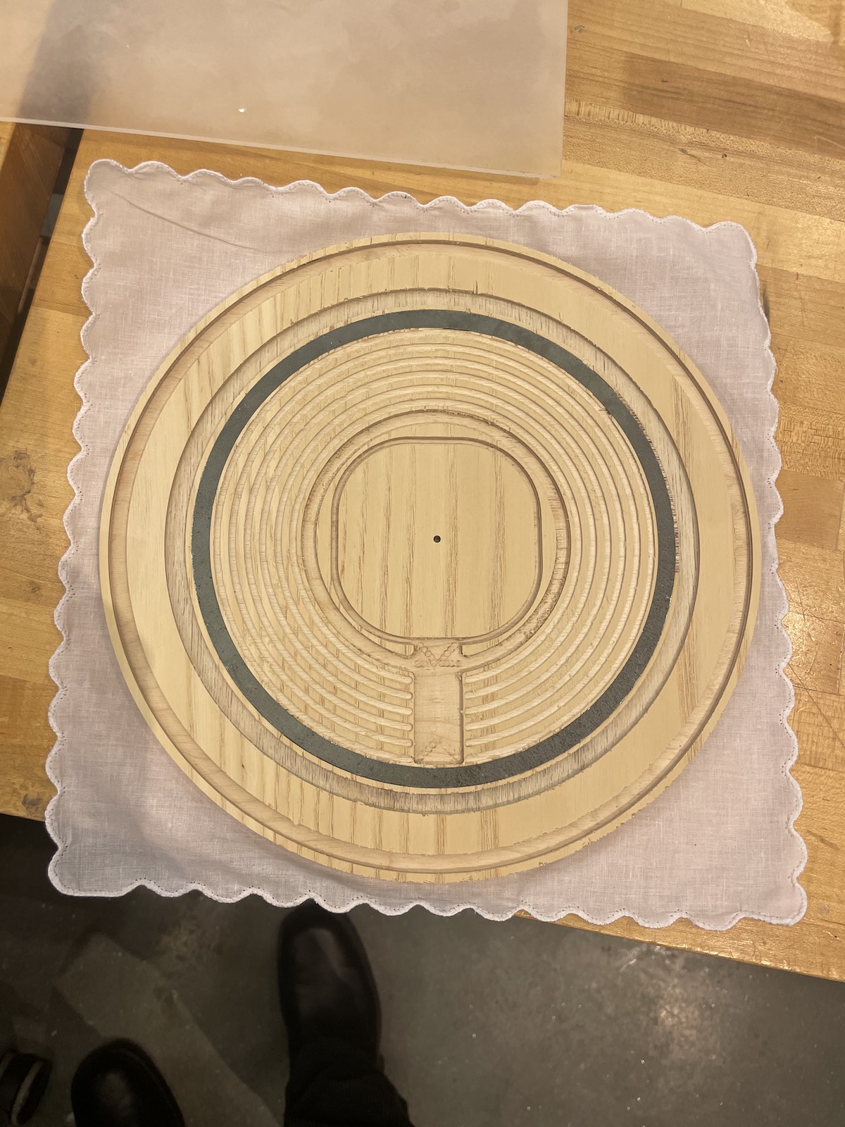
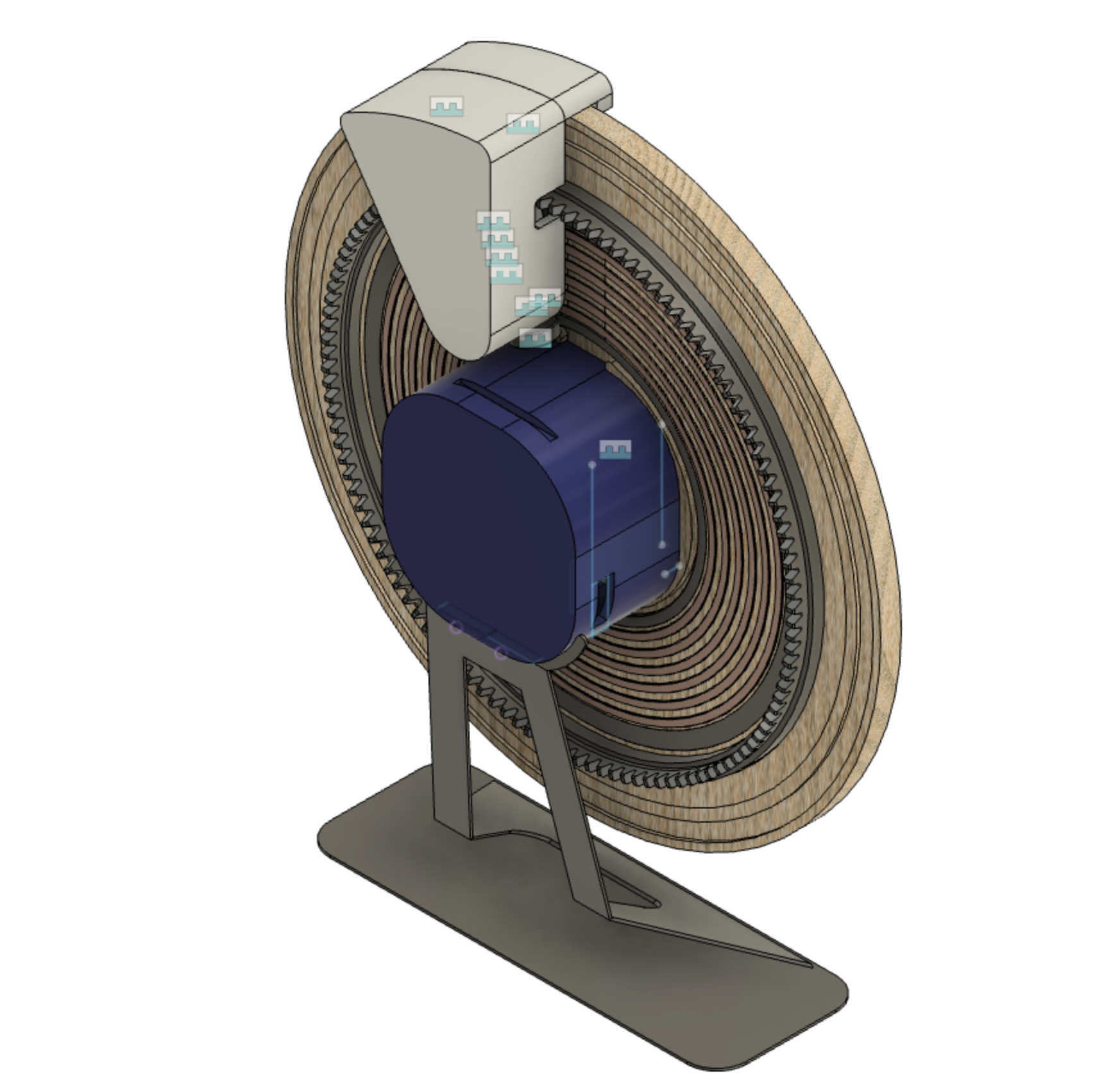
I used the Zund Large Format Cutting machine for the clock face of my final project which is made of plywood with various concentric grooves used to mount the components of the clock on the back of the face. Each of these grooves has a specific shape and is cut into the plywood at a different depth. Therefore, manufacturing the clock face using the Shopbot would require four different tool changes, separating the work across four different files.
Using the Zund large format cutting machine and the expertise of Alfonso, we were able to make use of the Zund's automatic tool chain feature and prepare a tool paths for the entire clock face in one job. Preparing the file properly took less than 10 minutes and the cut itself runs in around 2 minutes. This drastically reduced the manufacturing time. Massive thank you to Alfonso for showing me this beautiful machine!
Waterjet
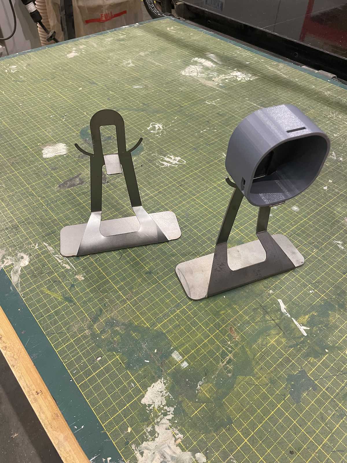
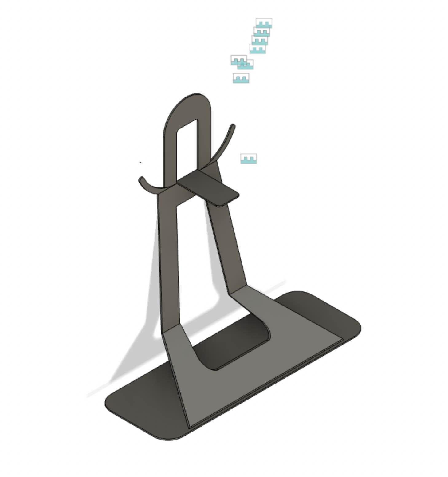
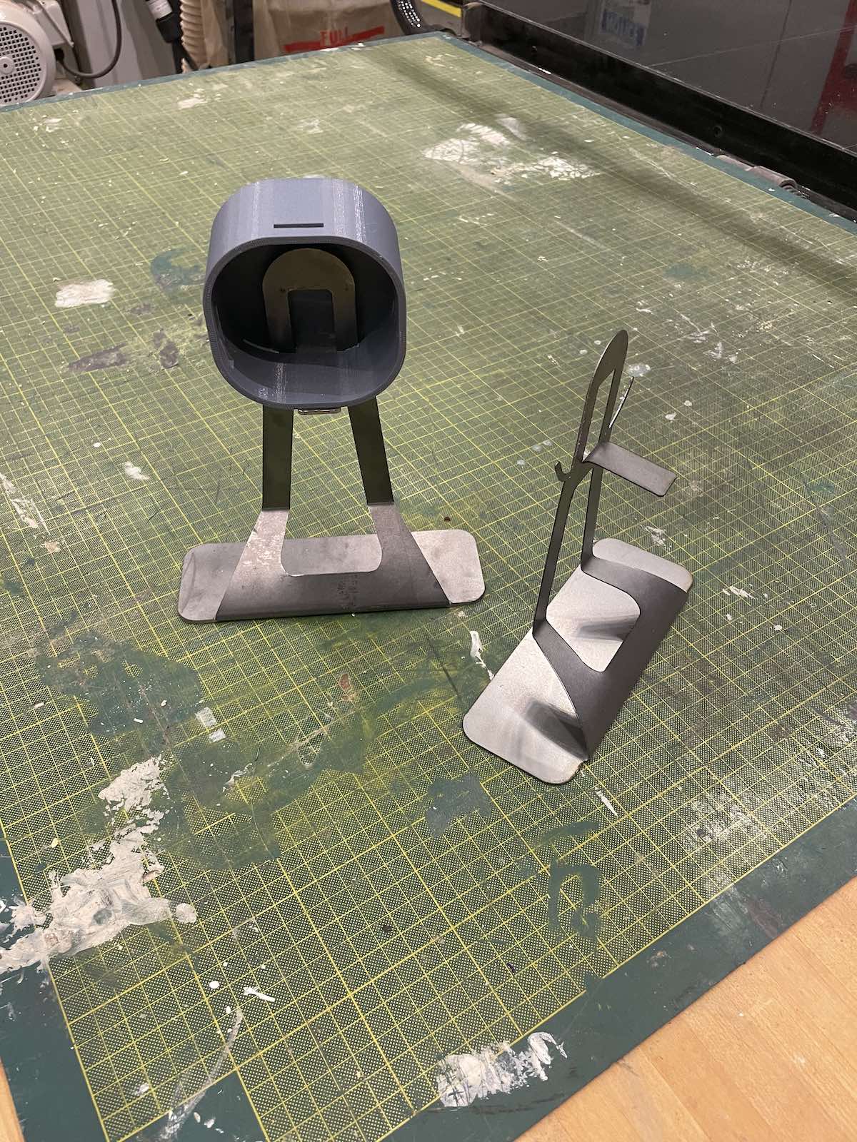
I used the waterjet to cut steel pieces for my clock. I cut both the clock stand and a circular steel ring used on the back of the clock face as an attractive surface for a magnet.
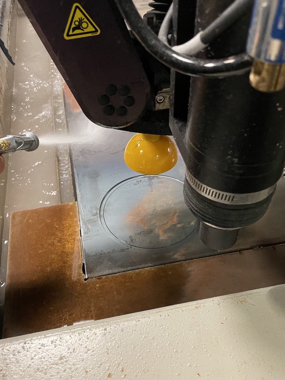
I cut the clock stand from one piece of steel and used bends to create the shape I designed in fusion. Huge thank you to John and Alfonso for helping me use this massive, somewhat ugly, yet effective machine.
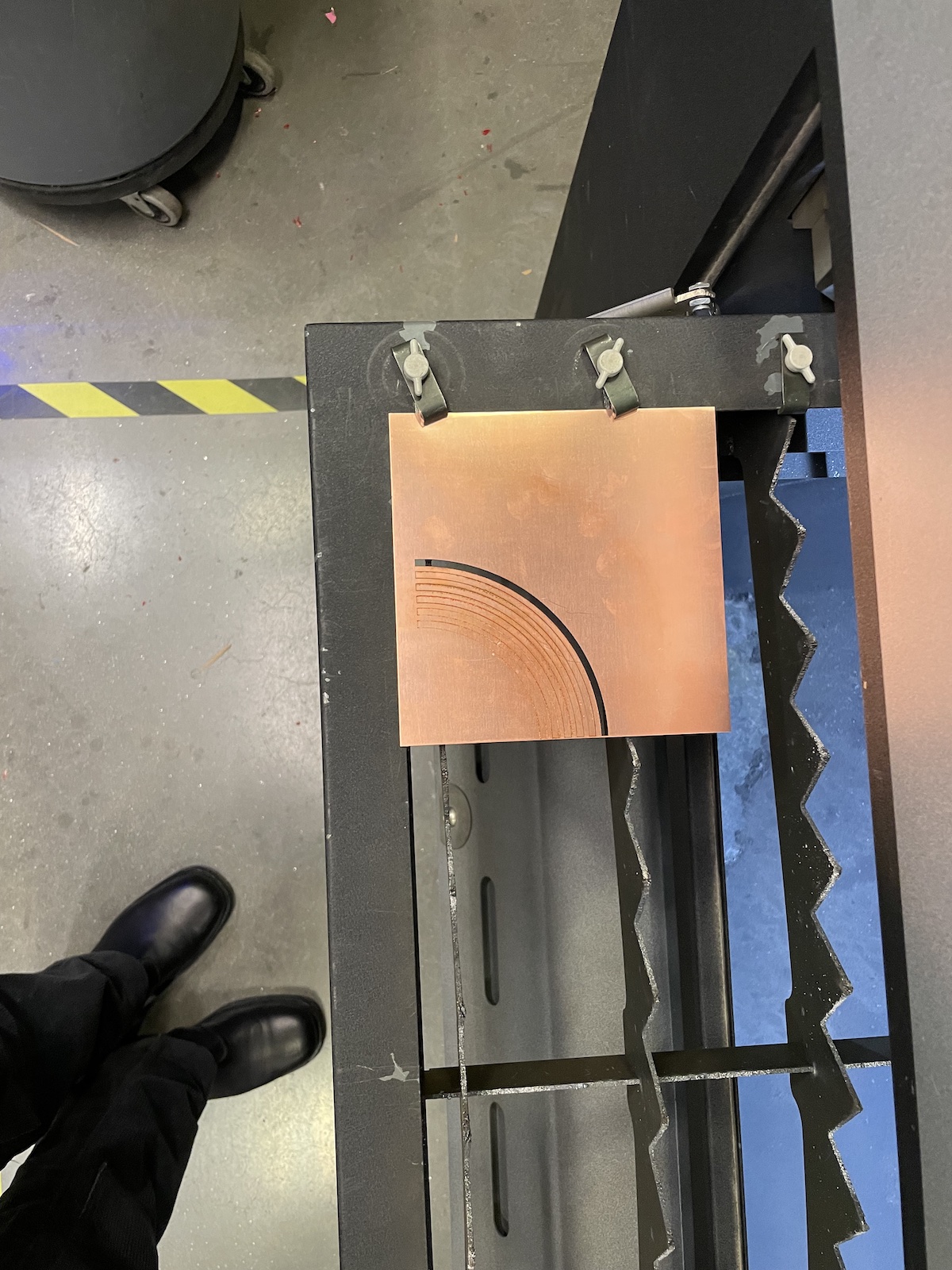
Fiber Laser
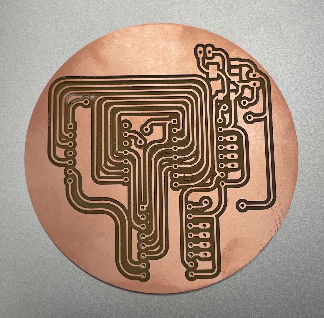
I attempted to use the waterjet to cut copper rings that will be used as conductive traces on the back of the clock face.
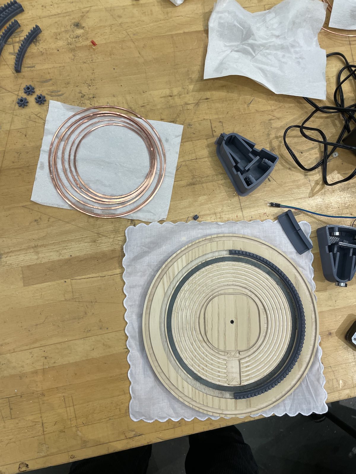
This process was difficult but John helped me out A LOT. We were able to cut out a few rings using the fablight, but we eventually switched back to the water jet machine.
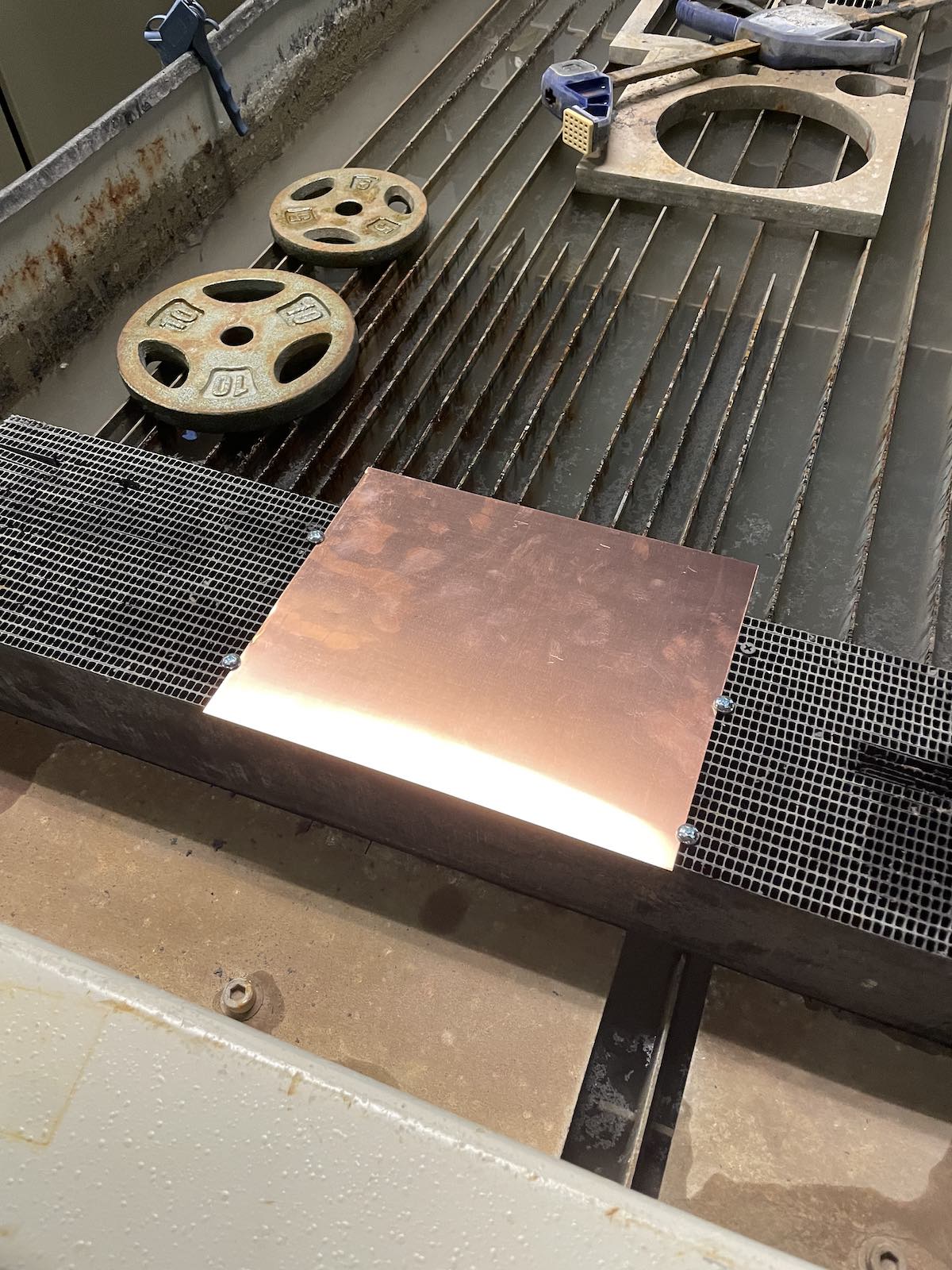
The copper material is thin and light, so the waterjet moved the material on the bed. We secured the material using screws and removed each ring after it was cut.
I learned a lot about the larger machines in the shop this week. Alfonso was IMMENSELY helpful as I iterated on my initial clock design and manufactured test parts. I learned a lot about machining from him as we worked on my parts. John helped me work with the thicker steel pieces I needed to cut and helped me trouble shoot machines that didn't work. Dave also helped me think through the radial contraint I needed to implement on the back of my clock design and suggested many different approaches that I ended up moving forward with.