Final Project
Problem Statement: How might we incorporate linearity into a "free-to-wander" immersive theater experience
Video
Overview
What does it do?
Blinks IR light
Who's done what beforehand?
TV remotes. It's the purpose, not the technology, that's different
What did you design?
The mask and PCBs
What materials and components were used?
3D filament, micro-usb, smd21e18 chip, si1145 light sensor
Where did they come from?
The CBA shop and PCBway
How much did they cost?
~$40 with shipping
What processes were used?
3D modeling in Fusion360 and PCB design in Eagle
What questions were answered?
Will this work?
What worked? What didn't?
The mask worked as a binary "on" "off." A separate system that could read and decode the IR light did not get finished.
How was it evaluated?
Did it turn on and react to an IR light 'on' switch?
What are the implications?
That this could be used for an escape room!
Brainstorming
For the first week of class, I brainstormed ideas. The main ideas were:
- A version of "disaster radio," a lora-based radio that could be set up in remote areas
- A "pond" made of LEDs with haptics that made the surface feel like putting your hand into water
- A surface that used magnets that could be repositioned and magnet gloves to create different shapes
- Glasses that use sensors to see people through walls (alternatively, see them breathing, their heartbeats, etc)
After speaking to someone on the teaching team, I chose #2, as it has the most individual componenets, and therefore room for an individual piece to fail while still having a "final" project at the end.
Sketches
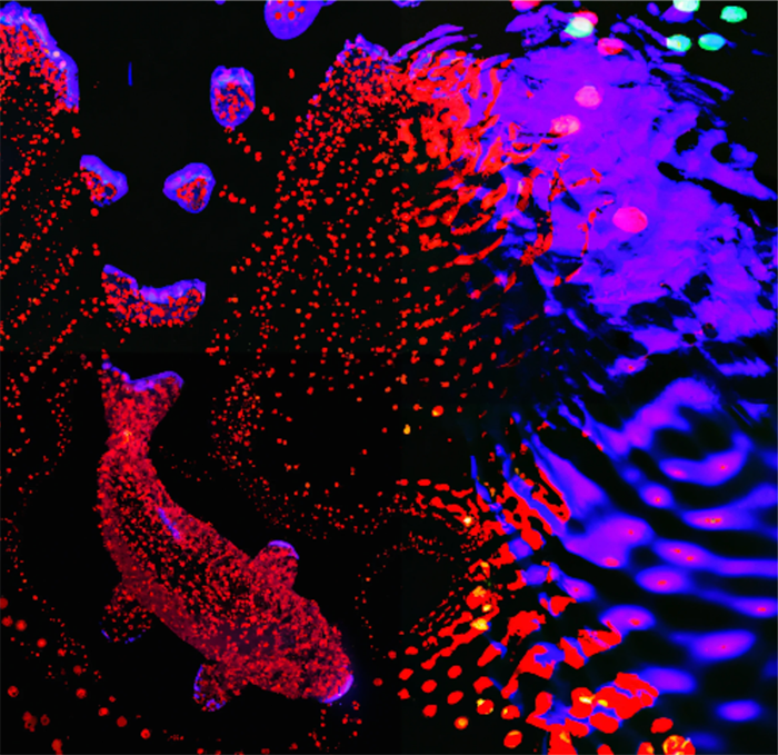
I used Dalle-2 to "sketch" some versions of what the final pond might look like, iterating until I got the view I wanted.

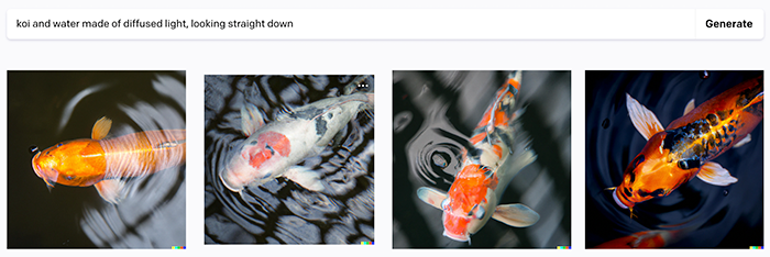
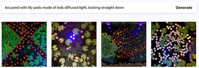
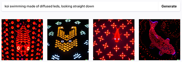
When I did, I used "outpainting" to draw the rest of the surface.
Mock-ups
Then I brought the image into Illustrator to create the full sketch.

I then modeled possible versions of the pond in Fusion 360. I've rarely used CAD software in the past, but was able to assemble and light a possible model.


Pivoting
I knew that I might end up changing this project as I learned more about what this class would be covering. Around week 5, this ended up happening.
For another project, I've been building glasses that protect biometric data using IR light. As I kept thinking about this project, I came up with an idea (during class!) that would apply the IR lights + wearables to another interest of mine: immersive theater / escape room.
The final product will be:
- A mask or other wearable that participants will wear.
- There will be IR leds embedded into the wearable
- These will get activated based on what the participant does: solving puzzles, experiencing certain scenes
Electronics Design
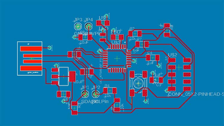
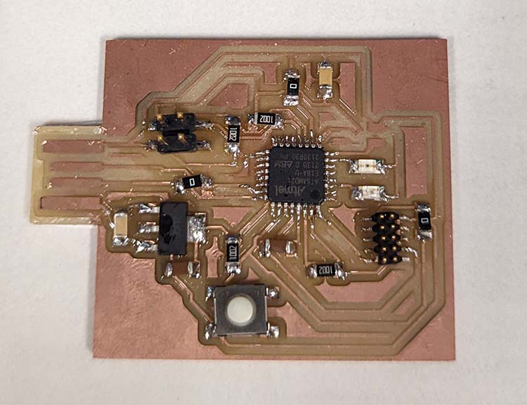
I designed a prototype board that's programmable to control IR LEDs.
Reference 0
Building Board 1
I looked at the Trinket M0 Eagle Schematic to see which of the SMD21E18 pins corresponded with the M0 board pinouts. Then I built my board with a combination of that information and Jake’s ECAD Demo from last year.
I also plan to create a second, smaller board with the actual light sensor on it to go in the middle of the glasses, but am waiting on the SI1145 individual sensor component.
My previous prototype used an Arduino M0 Trinket Board, but I only wanted to reference the chip and create my own board with all my components on it. I compared the adafruit board pinouts with the chip pinouts, and set up my board in the same way (This would become a problem later).

Adafruit M0 Trinket Eagle Schematic
I had ongoing challenges finding the right components. The capacitors in the fab library I referenced were too big, as were my pins to connect to JTAG to install the bootloader. I pulled in the “correct” components by copying and pasting them from HTMAA MIT example boards in the Fusion account, since I wasn’t able to find them in the fab library.
I was using the back of my board as a ground plate with vias. I used the ones in the CBA lab, some went in well, others got squished. Rivets are small metal rings that get installed with a lever that pushes them into the hole in the board.
Board 1 with rivets installed
Okay, so now I have a board. Was it working? Unclear. I used a multimeter to check connections, specifically checking for continuity throughout my board.
A bunch of my rivets weren’t connected. I globbed solder on both sides, which seemed to fix it.
My other issue was the ridiculously small size of my USB to USB-c dongle. I cut the USB with scissors so it would fit – a very ugly solution. Other mistake: I soldered wires directly onto my board which was a huge mistake, they pulled my traces up and were terrible. I replaced them with standalone through-pins which were also terrible.
THEN I realized I had used a 5v converter by accident (there was no 3.3 in the shop and I just went by shape). I pulled it off my board carefully, a process that ripped up parts of my board. I went into the CBA lab to get a 3.3v converter from one of the drawers. I didn’t check and just trusted the label, huge mistake. It was another 5v converter. At that point I gave up, RIP board.
RIP board 1
Board 2
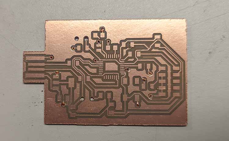
Okay, back to Eagle. I redesigned my board in a couple of hours and milled the new one. Quentin encouraged me not to use rivets this time. Okay, now it’s 11pm on Monday, I left the lab to head home. On the way there I see Quentin in the banana lounge, where he informs me I have two shorts. Next time I should set the mods width to 15.9mm instead of 16mm, since even with the recommended design rules my board ended up with these. I cut them apart with an exacto-knife before assembling the board.
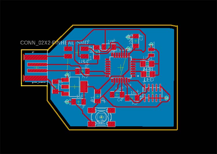
Board 2 design with rivets
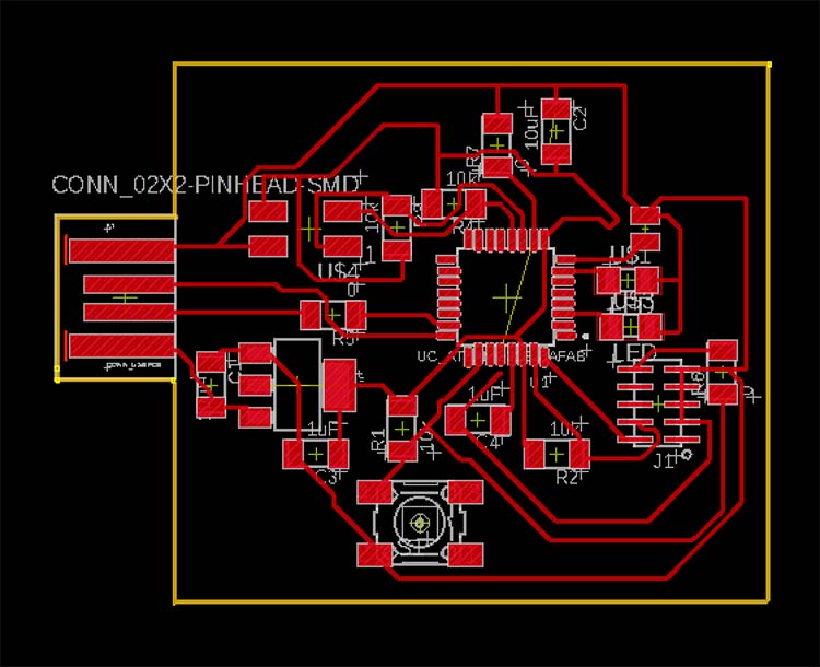
With rivets removed!
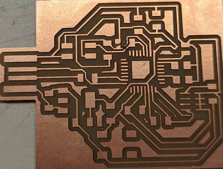
Board 2 freshly milled
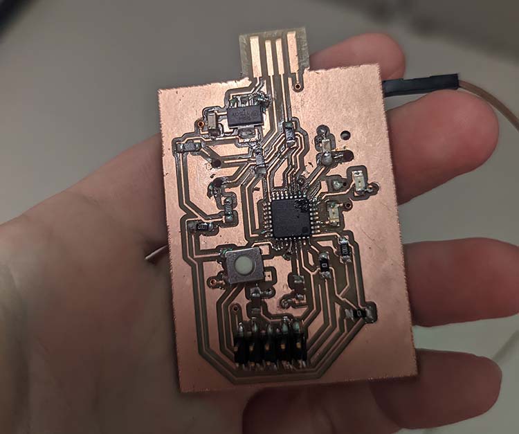
I assembled the board with my precious last 3.3v converter.
Board 2 assembled
Installing the bootloader was straightforward, I used the board script on the MTM site by connecting the board via JTAG.
At first after installing the bootloader and plugging the board into my laptop, my computer wasn’t reading that the board was connected. Miana explained that this was because the USB-3 dongle was expecting faster data exchange. I used a USB-2 dongle in the lab instead.
When I went to load the code I had previously prepared, everything crashed and I had to reinstall the bootloader on the chip. Okay, no worries. I ran blink code to make sure anything was working. No! The pinouts on the chip with this bootloader are different than the Adafruit version of the same chip. I update these based on the P#s on both diagrams, and the blink code worked!
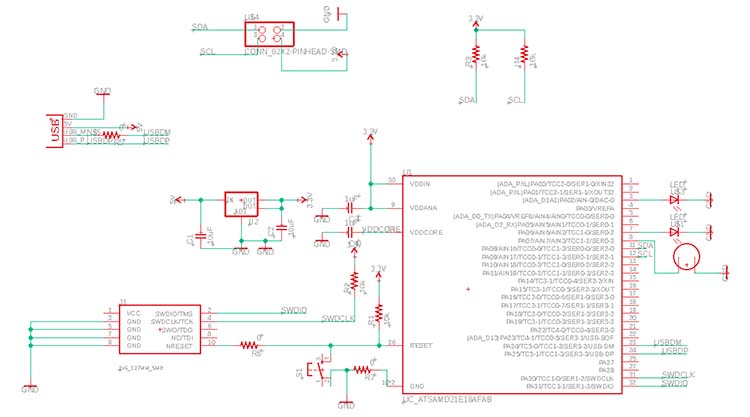
My Board Design
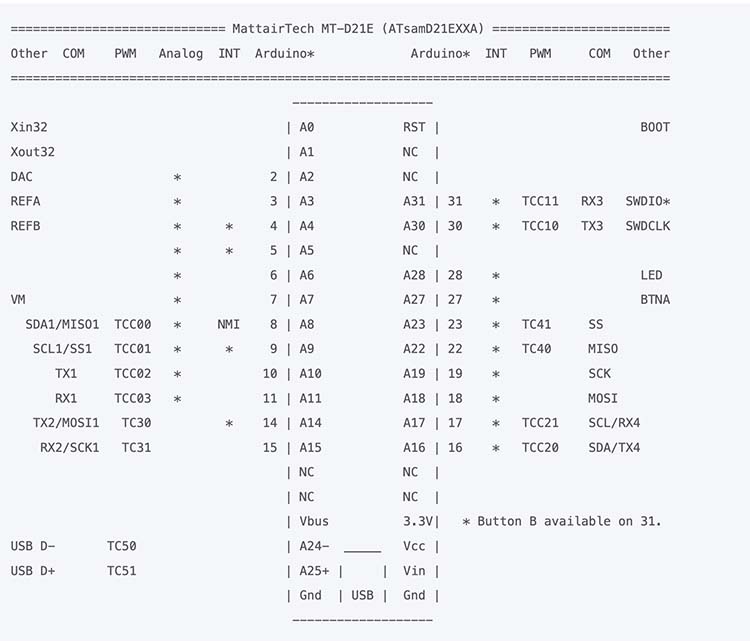
Bootloader Pinout re: MTM
Adafruit M0 Trinket Eagle Schematic
My other code kept crashing the chip. After isolating and running specific lines of code, I figured out that the crash was related to calling the SI1145 library when it wasn’t successfully set to anything.
I fixed this in the code, but the sensor still wasn’t sending data back to the chip. I used and oscilloscope to see if everything was connected properly. It was, but the SCL and SDA pins were staying at a solid 5V. Anthony helped me debug this, the Adafruit version of the chip and my chip with the MTM bootloader were using different I2C pins. We updated the SI1145 library to reference Wire1 instead of Wire on line 154 of Adafruit_SI1145.h, and FINALLY everything worked.
Code
          #include

          #include "Adafruit_SI1145.h"


          Adafruit_SI1145 uv = Adafruit_SI1145();


  bool running = false;


  void setup() {

      while (!Serial) ;


     if (! uv.begin()) {

        Serial.println("Didn't find Si1145");

        while (1);

     }


     if (uv.begin()) {

        running = true;

     }


       pinMode(2, OUTPUT);

      pinMode(6, OUTPUT);

     pinMode(7, OUTPUT);


  }


  void loop() {

     if (running) {

        float Vis = uv.readVisible();

        float IR = uv.readIR();

        float UVindex = uv.readUV();


        UVindex /= 100.0;


        if(IR > 274) {

           digitalWrite(2, HIGH);

           digitalWrite(6, HIGH);

           digitalWrite(7, HIGH);

        } else {

           digitalWrite(2, LOW);

           digitalWrite(6, LOW);

           digitalWrite(7, LOW);

        }

     }


       delay(1000);

  }
Molding & Casting
Concept
I thought the mask was too large to be a reasonable product for this week, so I focused on a prototype of glasses as a first pass.
Design
I started by measuring my own glasses. At 5 inches across and 1 1/2 inches tall, they were just the right size to fit in the 3x7x1.5 inch mold for this week.
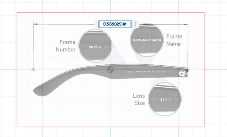
Then I went online and found a pair of sunglasses to reference for my design on. I took a screenshot of that image, and one of a glasses arm (which I learned are called temples).
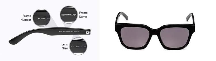
Credit: Givenchy GV Day 56MM Square Sunglasses
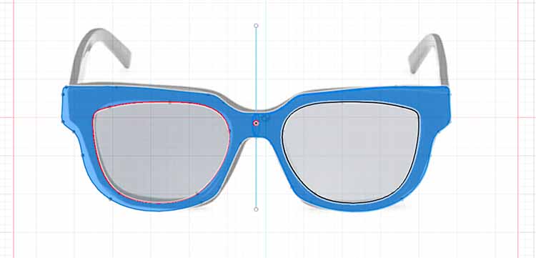
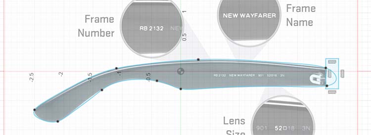
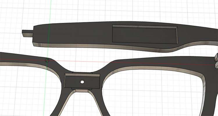
Using Fusion 360, I imported the image of the frames using Insert, Canvas. I used the Calibrate tool (get here by right clicking the recently uploaded canvas on the left-hand screen) to set two points on either side of the glasses frame, and set the distance to 5 inches. Then I created a sketch and traced the image of the frames using the Fit-point Spline tool. Then I mirrored my traced shape.
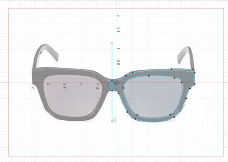
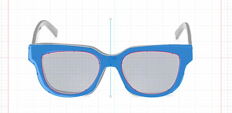
I added a hole in the center for my IR light sensor to sit behind. This didn't end up in the final product, because it was smaller than the bit in the CNC, a consideration I missed during my design phase.
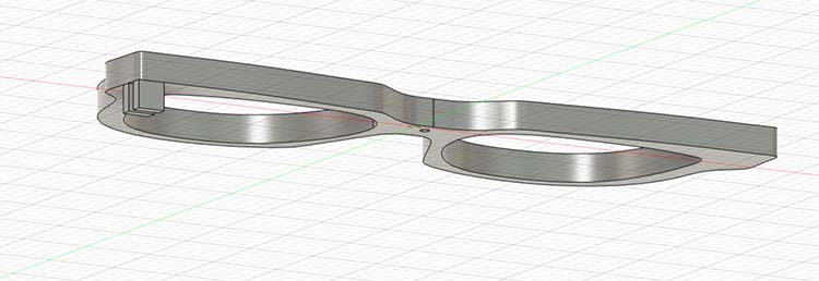
I extruded the shape and designed additional nubs to connect the temples. These also ended up being too small and weren't cut out in the final part :(
I repeated the process for the temples, and then set everything to fit on a 3x7 plane.
Calibrating the size of the temple (will end up being 5 inches)
Designing a sketch with the image as a reference. I used the Trim tool to remove the curved edge on the right.
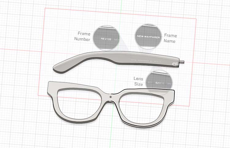
Final pieces extruded
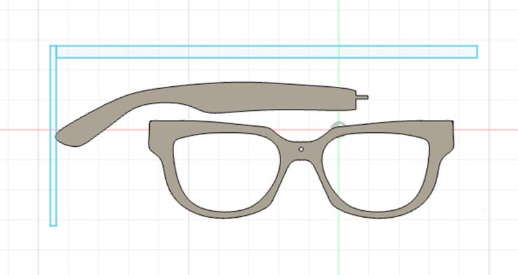
Pieces fit onto a 3x7 plane
I then went back in and added space to fit electronics into the design. This was done by creating a sketch and extruding the shape as usual. The software automatically removed material with the extrusion instead of adding it.
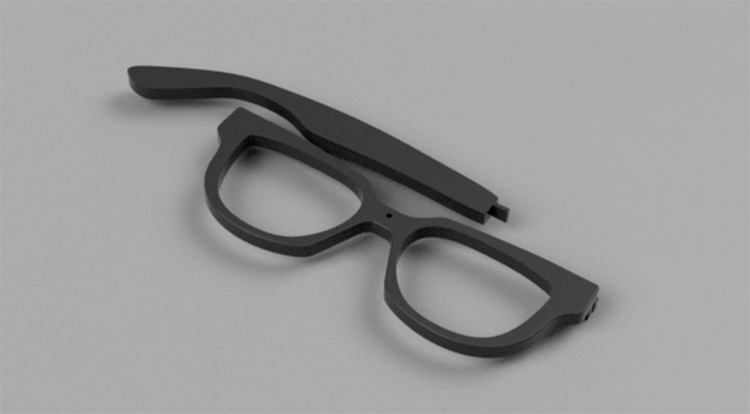
Final render
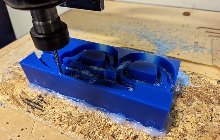
CNC
The steps here were to:
- Hot glue a block of wax to a piece of wood
- Connect to the CNC base with screws
- Prepare the file on CAM and send to CNC
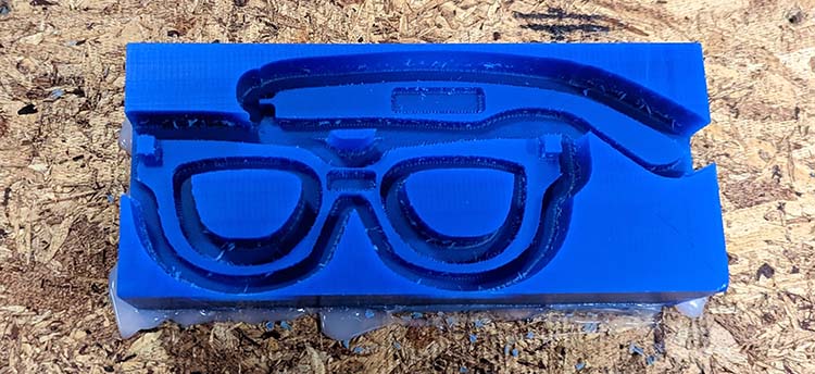
Mold-making
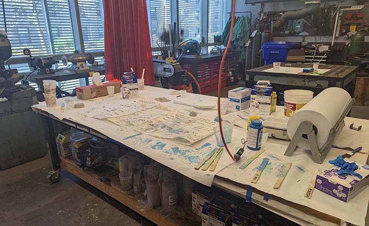
molding & casting table!
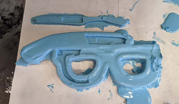
I made my mold with Oomoo, following the steps provided: mixing A and B for 3 minutes then pouring into the mold. My first wasn't great and had a lot of bubbles showing. I poured a second one later in the day that came out a lot better.
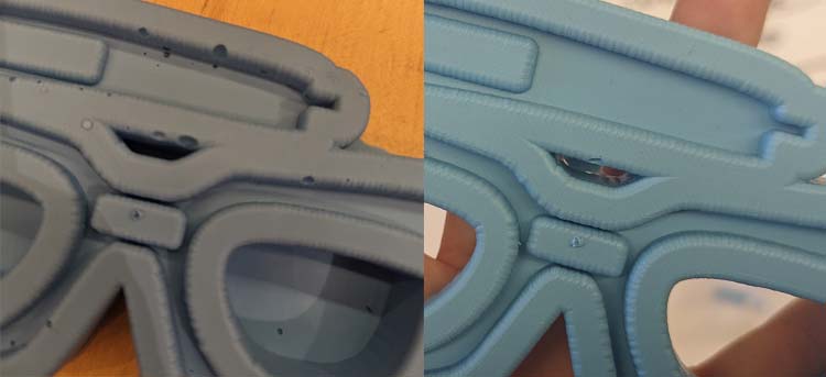
Comparing mold attempt 1 (left) and 2 (right)
Material Experiments
My first attempt to use the mold was to use metal as a material. The metal gets melted at 350 degrees in a little oven and then poured into the material. I wasn't able to get a super smooth surface with this. I attempted to file it down, and the glasses broke in the middle (what will become an ongoing problem).
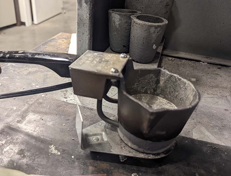
Melting the metal
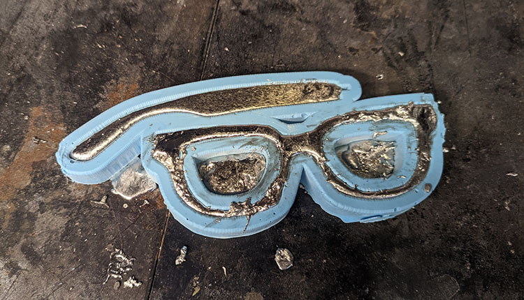
In the mold
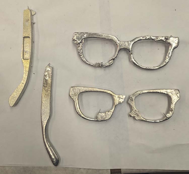
Mixed outcomes
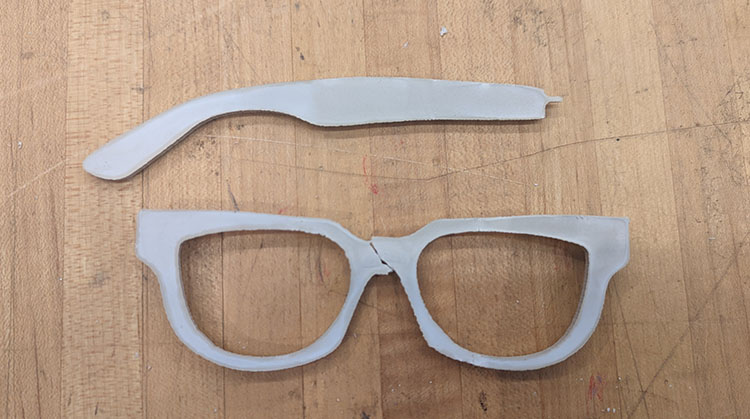
Moving on from metal, Hydrostone is apparently the hardest plaster. Knowing that my design could be fragile, I went that route, mixing using the island method.
It looked great in the mold, the top smoothed out really nicely in a way the metal didn't. However, the frame cracked as I took it out of the mold.
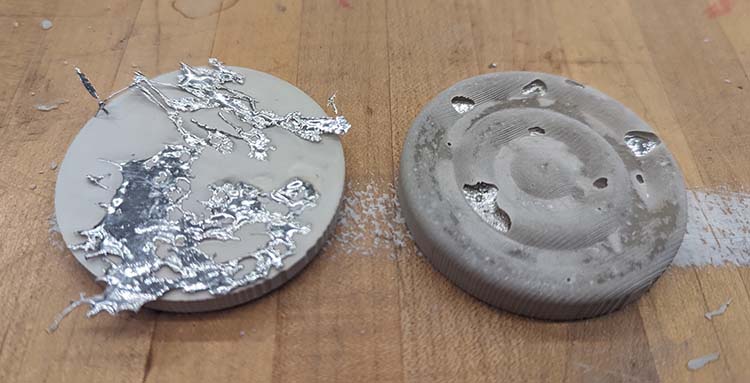
I also did some tests mixing the Hydrostone with leftover metal shards. I like the effect of leaving them on the bottom, but I'd want to find ways to make the effect more uniform.
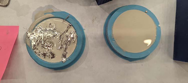
I knew from other students yesterday and an oomoo-in-oomoo cast was an option. The oomoo seemed much less fragile, so I sprayed and brushed my mold with an anti-stick material and tried to create an oomoo version of the glasses themselves.
This was an absolute failure. One mold was fine, but the other had merged and totally ruined the mold. The part that worked was way too floppy to be reasonable glasses.
Ordering PCBs
My final project is going to be a wearable (a mask), which makes the size of my electronic components important.
I spent the first part of the week redesigning my board from Embedded Programming week to be as small as possible.
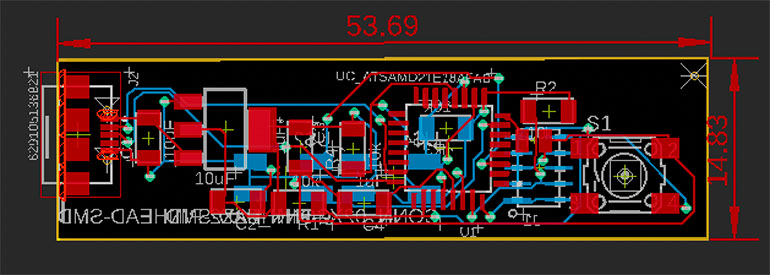
Main PCB
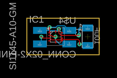
Light sensor
The boards were ordered from PCBWay. I prepared the files in the "Manufacturing" Tab of Fusion. First, I prepared everything with "CAM Processor" (the selection is in the top bar of the Manufacturing tab) and then exported the bundled .zip file to upload with "Export Gerber etc".
I had to wait about an hour for my uploads to be approved. After that, ordering was easy, and about $1/board.
Mask Design
I tried a technique that I thought might lead to a mask that looked like it had been purchased in a store using the shop's vacuum forming machine. I learned a lot about how to make a better mold and how to handle the plastic material.
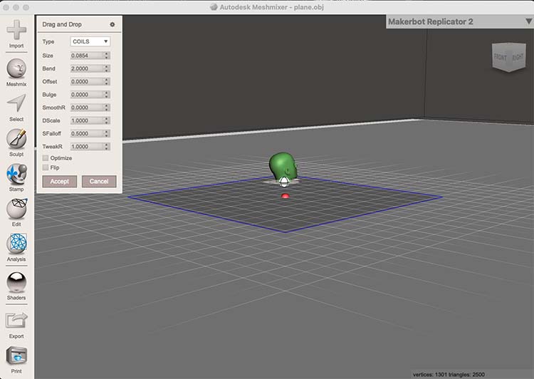
I designed the initial mask using Meshmixer, Fusion360, and Blender
In Meshmixer, I used the pre-existing head model in the software and cropped it to make a rounded mask shape.
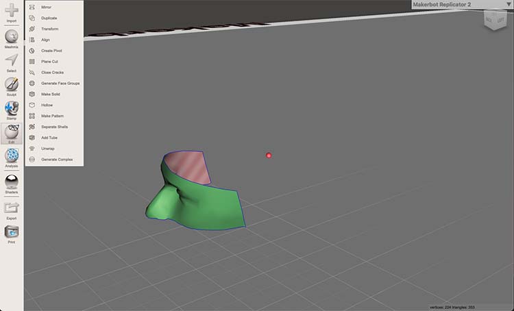
The mask was turned from a mesh into a body in Fusion360, then brought into Blender to give it depth.
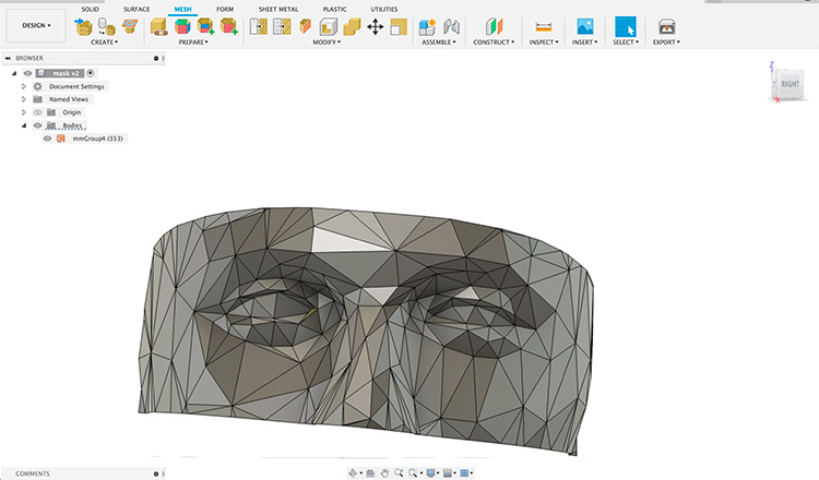
Imported into Fusion360
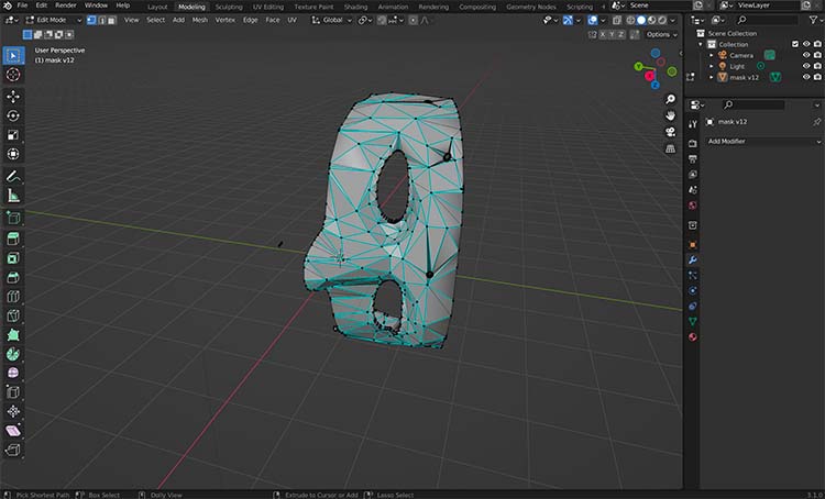
Editing in Blender
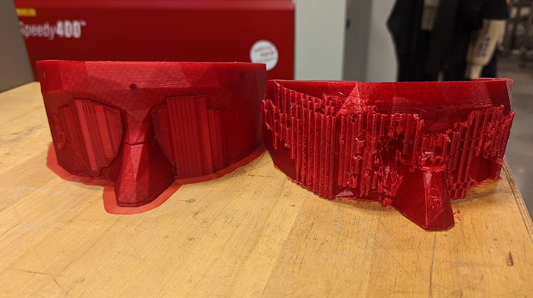
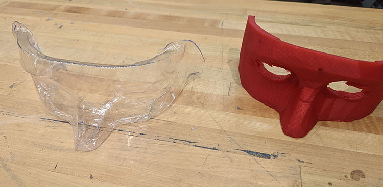
3-D printed masks on the Ender (left) and Prussa (right)
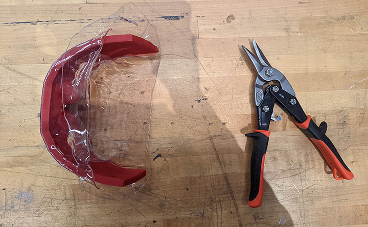
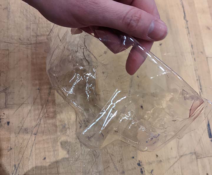
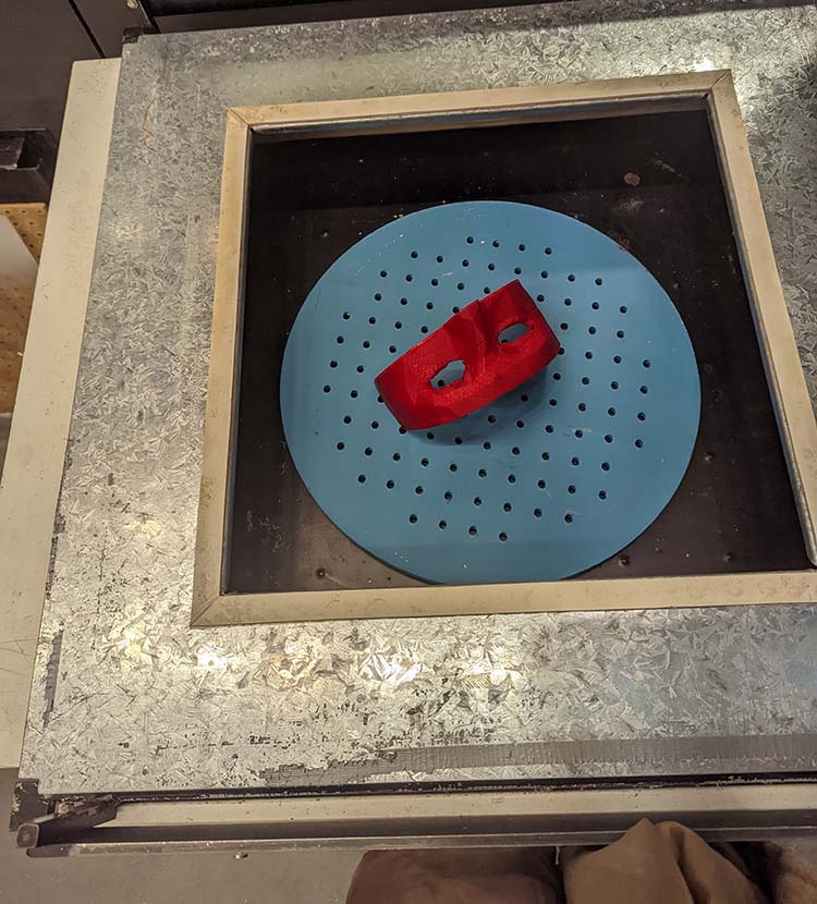
To use the vacuum forming machine, first load in the object to make a copy of.
Then, cover the top of the machine with a plastic sheet. Turn on the machine to warm it up and cover the top.
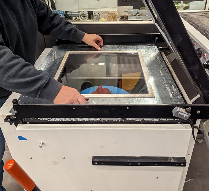
Once the plastic is pliable when pushed, it's time to create the new object. Pull up on the lever to both raise the bed and hold the green button to vacuum out the air.
After that, the plastic is still in a sheet. This is difficult to cut out, but out of all the tools, shears worked the best.