INTRODUCTION

This week's assignment was to write an application that interfaces a user with an input &/or output device that we have made in the past weeks. I had been working with liquid crystal elastomers towards my final project and for output devices week I had done a liquid metal embedded LCE for digital control of liquid crystal elastomers through joule heating. I had a few devices that broke due to electromigration effect, which I came to learn through this project. Below I unfold the challenges, demonstrate a successful LM heater encapsulated within LCE controlled with an h-bridge circuit (as alleaviation of the electromigratory effect) and allow control through a simple interface.
Electromigration of Liquid Metals
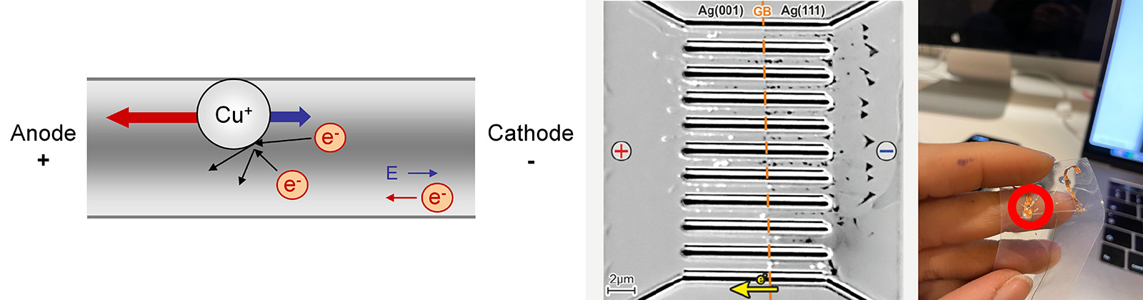
Electromigration is the movement of atoms based on the flow of current through a material. If the current density is high enough, the heat dissipated within the material will repeatedly break atoms from the structure and move them. This will create both 'vacancies' and 'deposits'.
Electromigration is a known concern in solid state circuits and can cause open or short circuits. Recent efforts have focused on the role of electromigration in limiting the amount of electrical current that can be transported through a thin trace of liquid metal. Here, I avoid electromigration failure through careful characterization and circuit design.
Electromigration characterization and heater design
I characterized the influence of electromigration by subjecting LM circuit traces to varying amounts of electrical power. LM traces were patterned onto polydimethylsiloxane (PDMS, Sylgard 184) as a test. Eutectic gallium-indium (EGaIn, In and Ga from RotoMetals) was used as the LM alloy due to its low viscosity (1.99 × 10⁻³ Pa s), high conductivity (3.4 × 10⁶ S m−1), and negligible toxicity. First, the maximum current that could be applied before failure was monitored. Current was applied to samples of four different widths and two different thicknesses on a substrate made with PDMS either uncovered or covered by a second layer of PDMS. The positive and negative terminals of the LM traces were ≥2.5 times the width of the channel so that breakup could be observed in the narrow channels by optical microscopy rather than at the contacts. The contact area had a width of 5 mm, and the channel widths ranged from 0.5 mm to 2 mm, with a channel length of 5 mm. A KORAD KA3005P power supply supplied current using a ramp function that increased the current by 0.2 A every 30 seconds until breakup occurred, defined as the moment the power supply read an open circuit (R ≥ 10 kΩ).
Next, I monitored the change in resistance as current was increased at set time intervals. For these measurements, LM channels (140 µm × 1 mm × 5 mm) were encapsulated in PDMS, and current was applied and increased at set time intervals of 30, 60, 90 and 300s until failure occurred. An 'unstable region' was defined as the point at which I observed a >15% increase of resistance. The effect of the current ramp and inverting polarity on electromigration failure was also evaluated. We applied five different current patterns after reaching the unstable region to determine how increasing current/changing the voltage polarity affected the resistance/breakup in the LM channel. The five current patterns involved increasing the current by 0.25 A every 90s until reaching the unstable region, followed by immediately: (1) reducing the current to 0 A and restarting the ramp; (2) reducing the current by 0.5 A and holding for 10 minutes; (3) inverting the polarity and then restarting the ramp at the original polarity; (4) reducing the current to 0 A and ramping the current with the polarity inverted from the original ramp; and (5) inverting the polarity, reducing the current to 0 A, and ramping the current with the polarity inverted from the original ramp.
Cricut for cutting LM mask
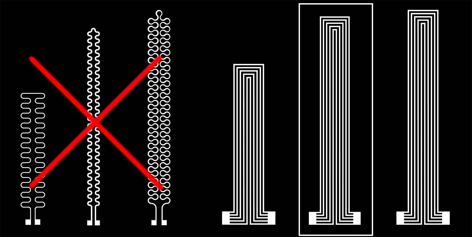
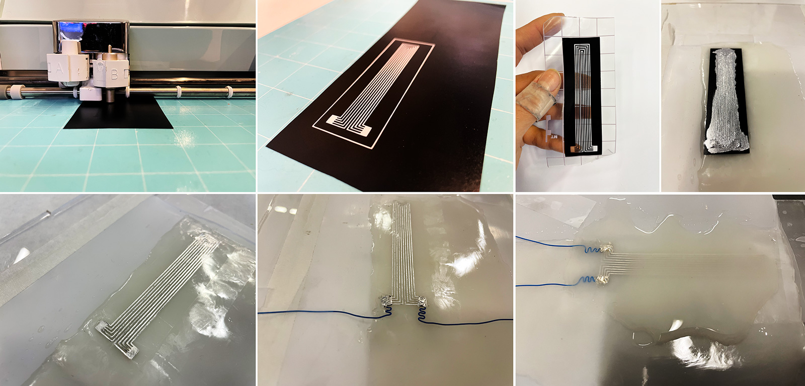
Due to suggestions in literature, a parallel heater design was chosen. In order to avoid an too wide of an actuator, I used 5 parallel heaters in my design with 500 micron width. From previous weeks I already know that cricut was capable of this hence I cut the mask with cricut using vinyl for a clean edge finish. Then I transferred this onto a semi crosslinked LCE sheet that I had casted on teflon sheet.
Embedding wires, sealing with silver epoxy, pouring top layer of LCE
Once the cut is done, I pulled it off the cutting mat using the transfer tape, and transferred it carefully onto semicrosslinked LCE. Then I applied the liquid metal paste I had made weeks ago using a q tip. Once the LM paste is evened out on the surface, I removed the mask using a tweezer. My LM channels looked good so I added the connection wires to each pad, and fixed them using silver epoxy. After a good hour of curing, I synthesized and poured the top layer LCE over to complete the device.
Testing the LM-PDMS composite under power supply as proof of concept
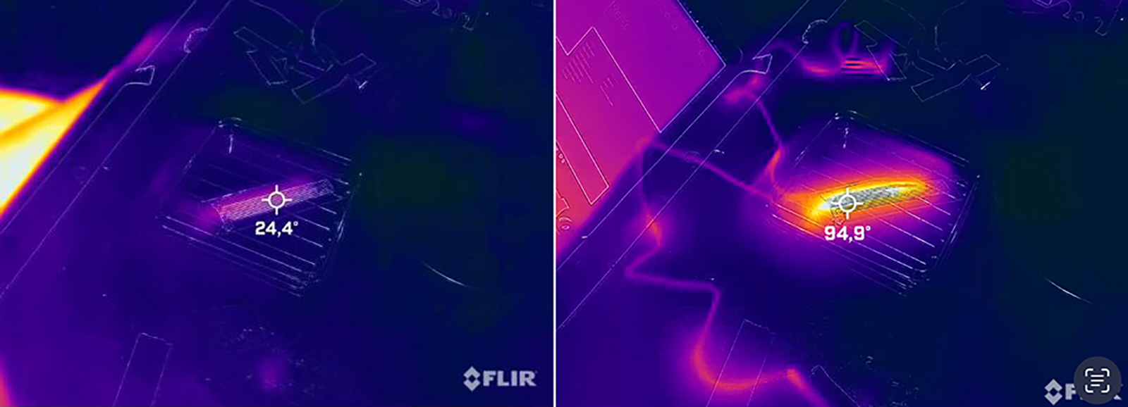
I tested an identical LM-PDMS composite to test if the inverse polarity really works by increasing the tempreature and platoes at a certain point. And yes, the researchers who suggested this were right! I was able to rise from 24 degrees up to 102 degrees eventually! Considering the critical region of my heater, I pushed up to 0.8A and then manually changed the polarity. Of course my manual change frequency would be rather slow however still I reached a high enough temperature despite my human control! After this, I was encouraged to make the h-bridge circuit given that the rate it alternates between polarities would be much faster.
Circuit and Control GUI
I decided to use Tkinter, a python based GUI builder, to create a graphical interface with my LM-LCE embedded actuators control through an h-bridge circuit.
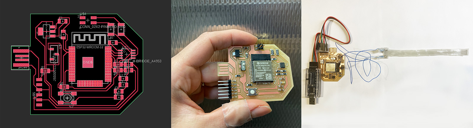
H-bridge circuit for alternating polarity
In order to reach above the transition temperature of LCEs, I had to change the polarity constantly hence Quentin suggested that an H-bridge would be a neat solution here as they basically do that! It is often used with steppers for rotation direction, and in my case it would change the anode and cathode in order to avoid electromigration and help with increasing the temperature until it platoes (in my case 120 degree Celcius!) Below is the circuit design and the circuit connected to my LM-LCE device.
Tkinter
Then started the extensive Googling in order to learn how Tkinter worked. It seemed fairly understandable, but there were a lot of moving parts, especially as Arduino and Python were interacting, so I kept getting confused. The main thing I learnt though was that I needed to import three main things in Python in order to get Tkinter to work: serial, time, and tkinter. Serial and time need to be imported in order to communicate with Arduino properly. Obviously Tkinter needs to be pip installed in order to be used. Also it is important to note that serial does not come pre-installed with Python, so I had to run 'pip3 install pyserial' in order to install it. I was able to write some very simple Programs using tkinter with my basic knowledge, but I was still feeling pretty stuck on figuring out how to put everything together. So I followed this awesome tutorial
First, I have to design buttons to press for sending data to arduino port via UART. In this project, my comport is com7, and baud rate is 96oo. It’s the regular and appropriate values of arduino board, by the way, if you want to connect wifi using ESP32, you will always notice that these boards use 115200 as its appropiate baud rate.
Python functions
Let’s see in python code, I’ve imported 3 modules; serial, time, tkinter
- serial >>> To communicate between arduino and python
- time >>> To manage everything about time
- tkinter >>> To build a GUI app
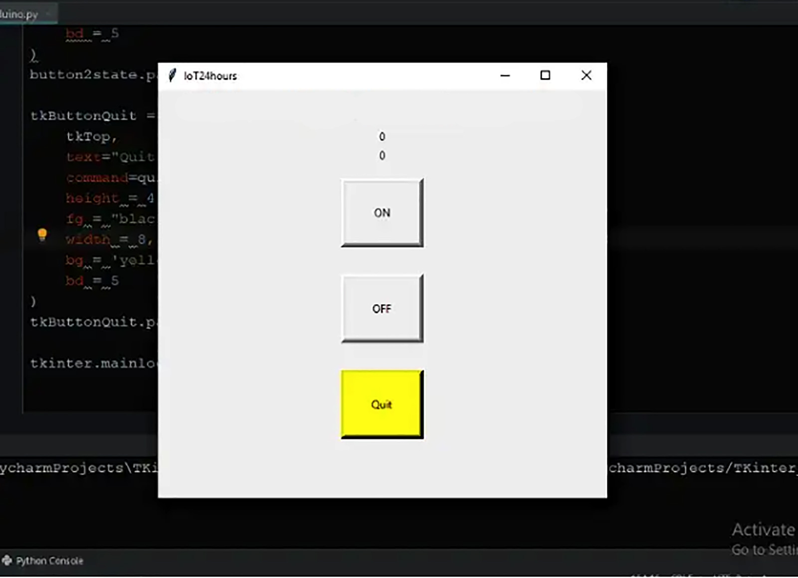
Buttons
- quit (Quit Button) >>> To exit the app whenever we want
- set_button1_state (ON Button)>>> To send character “H” to arduino, perhaps turn on an LED
- set_button2_state (OFF Button)>>> To send character “L” to arduino, perhaps turn off an LED
Python code
								import serial
								import time
								import tkinter


								def quit():
								    global tkTop
								    ser.write(bytes('L', 'UTF-8'))
								    tkTop.destroy()

								def set_button1_state():
								        global b
								        b += 1
								        varLabel.set("HIGH")
								        ser.write(bytes('H', 'UTF-8'))
								        varLabel2.set(b)
								        print(b)

								def set_button2_state():
								        varLabel.set("LOW")
								        ser.write(bytes('L', 'UTF-8'))

								ser = serial.Serial('com7', 9600)
								print("Reset Arduino")
								time.sleep(3)
								ser.write(bytes('L', 'UTF-8'))

								tkTop = tkinter.Tk()
								tkTop.geometry('300x200')
								tkTop.title("IoT24hours")
								label3 = tkinter.Label(text = 'Building Python GUI to interface an arduino,'
								                      '\n and control the heater',font=("Courier", 12,'bold')).pack()
								tkTop.counter = 0
								b = tkTop.counter

								varLabel = tkinter.IntVar()
								tkLabel = tkinter.Label(textvariable=varLabel, )
								tkLabel.pack()

								varLabel2 = tkinter.IntVar()
								tkLabel2 = tkinter.Label(textvariable=varLabel2, )
								tkLabel2.pack()

								button1 = tkinter.IntVar()
								button1state = tkinter.Button(tkTop,
								    text="HIGH",
								    command=set_button1_state,
								    height = 4,
								    fg = "black",
								    width = 8,
								    bd = 5,
								    activebackground='green'
								)
								button1state.pack(side='top', ipadx=10, padx=10, pady=15)

								button2 = tkinter.IntVar()
								button2state = tkinter.Button(tkTop,
								    text="LOW",
								    command=set_button2_state,
								    height = 4,
								    fg = "black",
								    width = 8,
								    bd = 5
								)
								button2state.pack(side='top', ipadx=10, padx=10, pady=15)

								tkButtonQuit = tkinter.Button(
								    tkTop,
								    text="Quit",
								    command=quit,
								    height = 4,
								    fg = "black",
								    width = 8,
								    bg = 'yellow',
								    bd = 5
								)
								tkButtonQuit.pack(side='top', ipadx=10, padx=10, pady=15)

								tkinter.mainloop()
Arduino code
								// Arduino IDE:
								// File -> Examples -> 04.Communication -> PhysicalPixel

								const int heaterPin = 13; // pin the heater is attached to
								int incomingByte;      // variable stores  serial data

								void setup() {
								  // initialize serial communication:
								  Serial.begin(9600);
								  // initialize the heater pin as an output:
								  pinMode(heaterPin, OUTPUT);
								}

								void loop() {
								  // see if there's incoming serial data:
								  if (Serial.available() > 0) {
								    // read the oldest byte in the serial buffer:
								    incomingByte = Serial.read();
								    // if it's a capital H (ASCII 72), turn on the heater:
								    if (incomingByte == 'H') {
								      digitalWrite(heaterPin, HIGH);
								      Serial.println("Getting H"); //print out to serial monitor to check state
								    }
								    // if it's an L (ASCII 76) turn off the heater:
								    if (incomingByte == 'L') {
								      digitalWrite(heaterPin, LOW);
								      Serial.println("Getting L"); //print out to serial monitor to check state
								    }
								  }
								}
Control with Button
I was finally able to turn on and off my device using a button and below is the result. Since the return of the sample back to original was veeery slow, I cut it out of the video but after a minute of cooling down it returned to near original state.