A machine that takes in an image, vectorizes the image, and sketches
Framework
Motivation: I love flipbooks as well as all things animation. Some of my favorite movies growing up have been animated. Having tried my hand at animation, I know that it is a labor intensive (but well-worth-it) media form. I wanted to create the first MVP of a sketching machine that can take in an image from a user input, vectorize the image, andn then sketch it on paper. The idea is that by having a machine draw, in future iterations multiple frames can be drawn and a rolling mechanism can potentially be implemented to let it continue drawing pictures (the user should be able to input a video, then the machine does all the work of selecting and drawing frames to then be cut out.
The overall framework of this project has three components: mechanical, electronics, and software. The way they interface with one another is described in this diagram below:
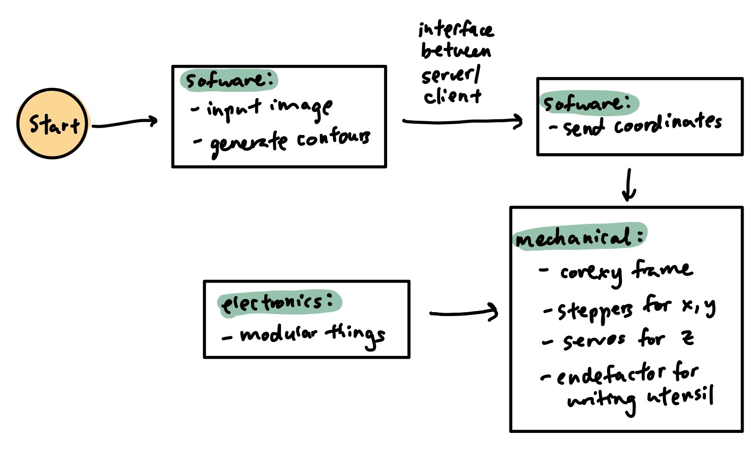
The user begins on the software side by inputting an image to a script that can then generate contours from the image. Then, we need a working interface between the server side and the client where we can send coordinates to the machine. In order for the mechanical components of the project to be able to interface with the software, we need to have electronic boards recognized by modular-things. Finally, on the mechanical side, we have a corexy frame, steppers, servos, and an endefactor that carries out the task of sketching.
Mechanical
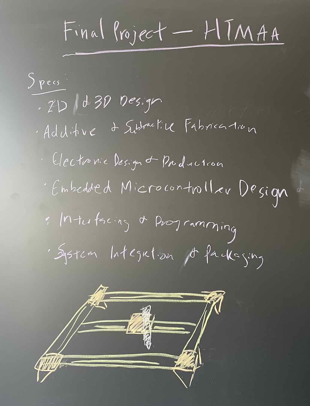
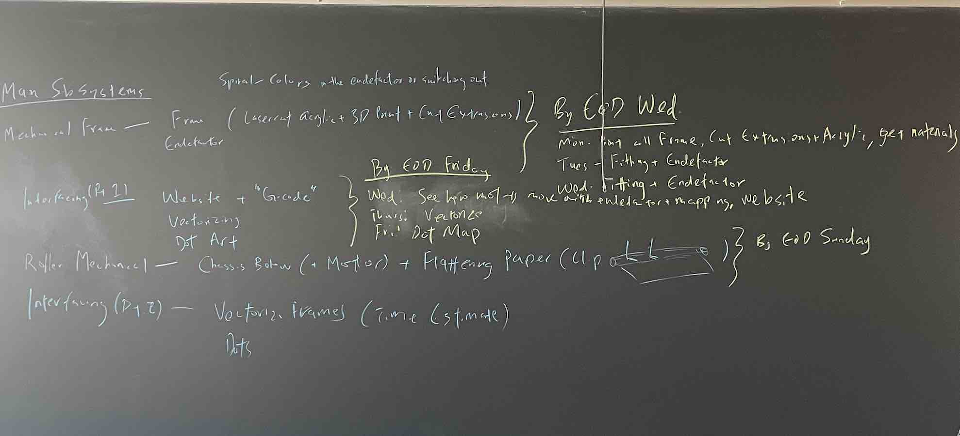
The first step (before all else), was to determine how to split the remaining time dedicated to this project among the tasks. Using a blackboard, I began triage and understanding how to spiral out this project. By splitting into the specific modules and understanding where documentation existed, I was able to manage my time properly.
Using Jake's Urumbot XY machine, with extensive documentation here, I began building out the corexy machine.
I began by laser cutting all of the bearing plates, pulley mounts, and feet of the system. I cut using 1/4" acrylic and found that a few adjustments needed to be made. For example, our group during Machine Week made bearing plates with flexures to minimize stiffness in DOF and provide compliance in the design. I adjusted our group's flexures (making the rectangular cut outs larger, moving the holes for the bearing wheels in to tighten the way the plates hugged the extrusions) based on my design.
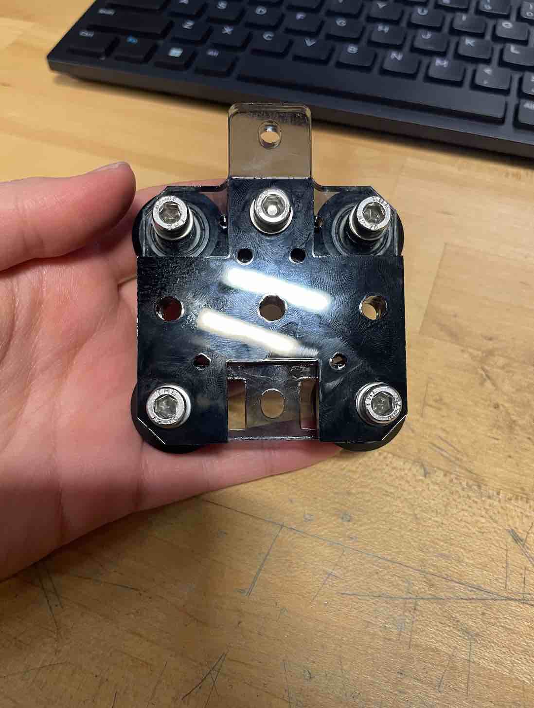
This is an adjusted flexured bearing plate:
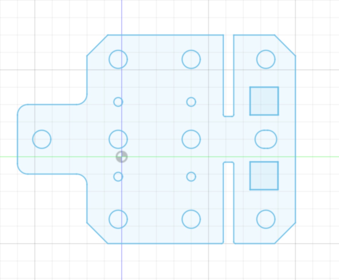
This is a cross for the plates mounting the endefactor that can help distribute the stiffness better:
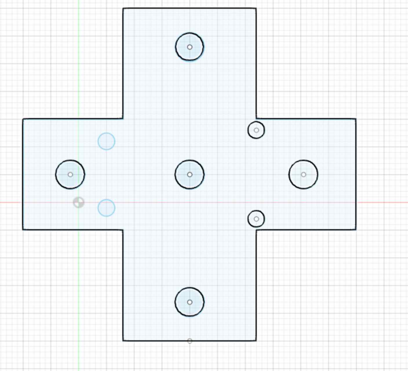
Moving the mounting holes for wheels with bearings was a pain because the difference between plates holding and plates snapping would sometimes be fractions of a milimeter. Here are photos of over 9 plates that snapped and I iterated through:
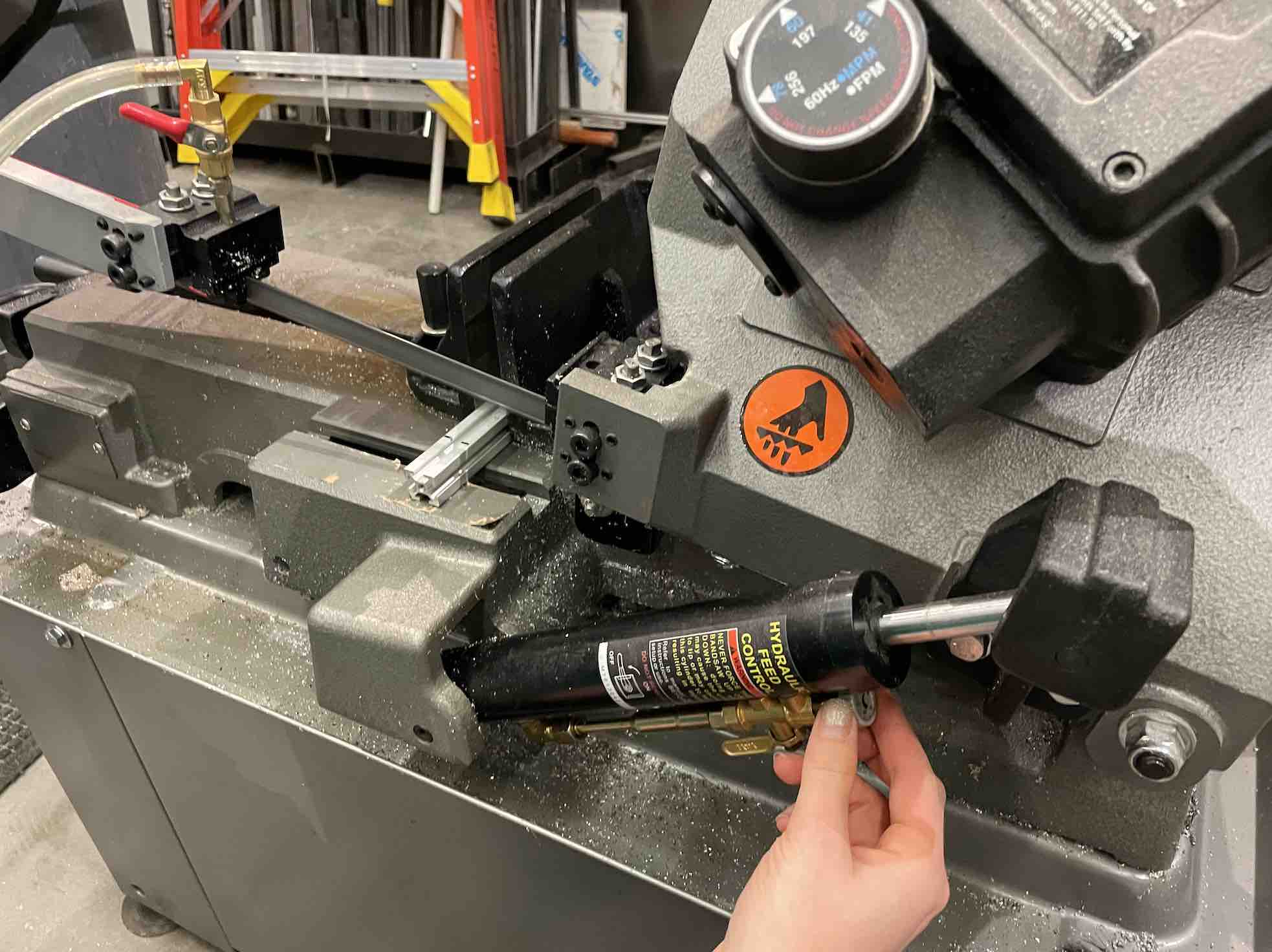
Another step in this process was cutting extrusions based on the dimensions I wanted. I chose to use a 17" by 17" base, which meant adjusting some of the precut T-slotted 80/20 Aluminum extrusions. Vera very kindly showed me how to use a saw!
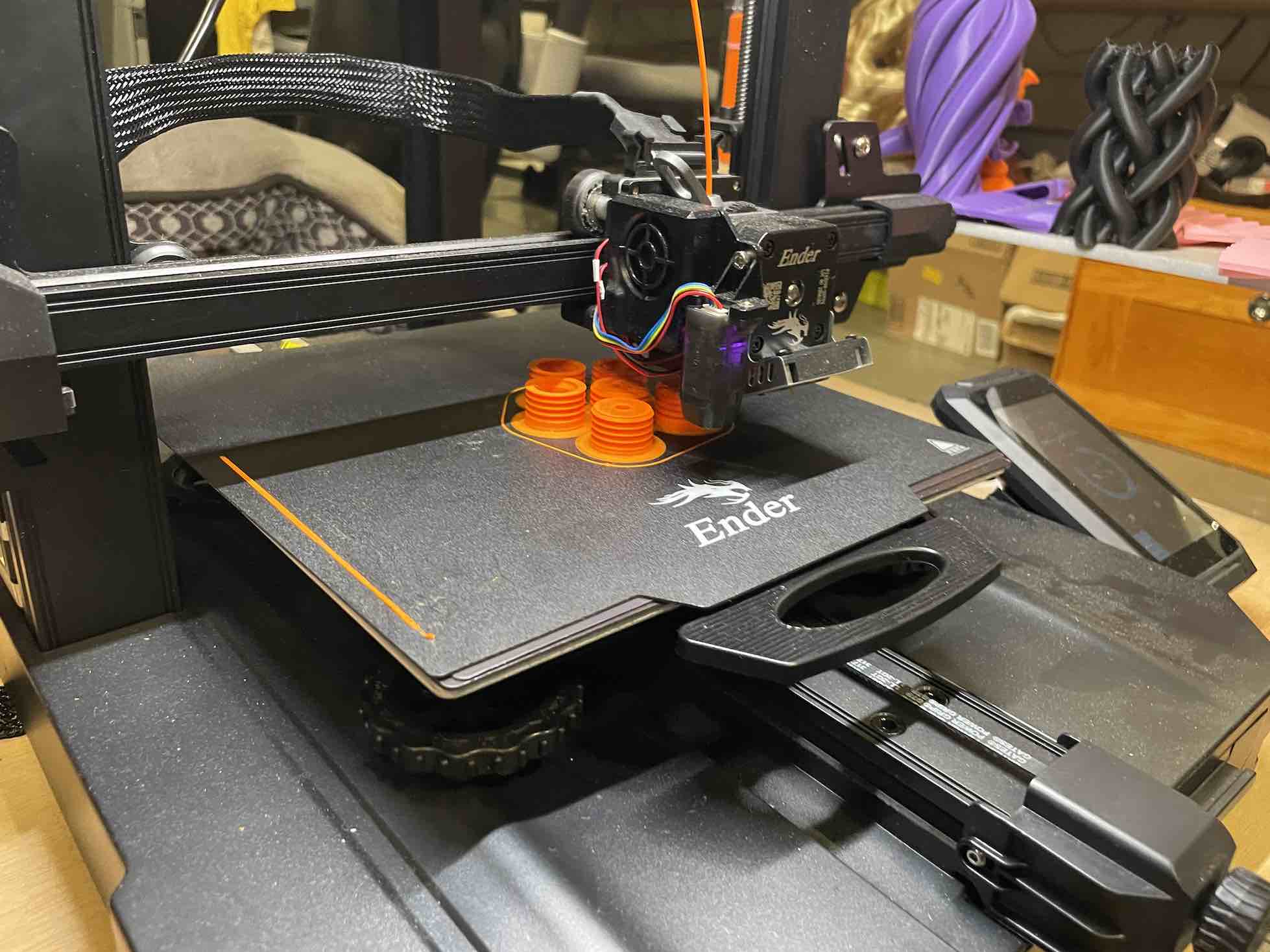
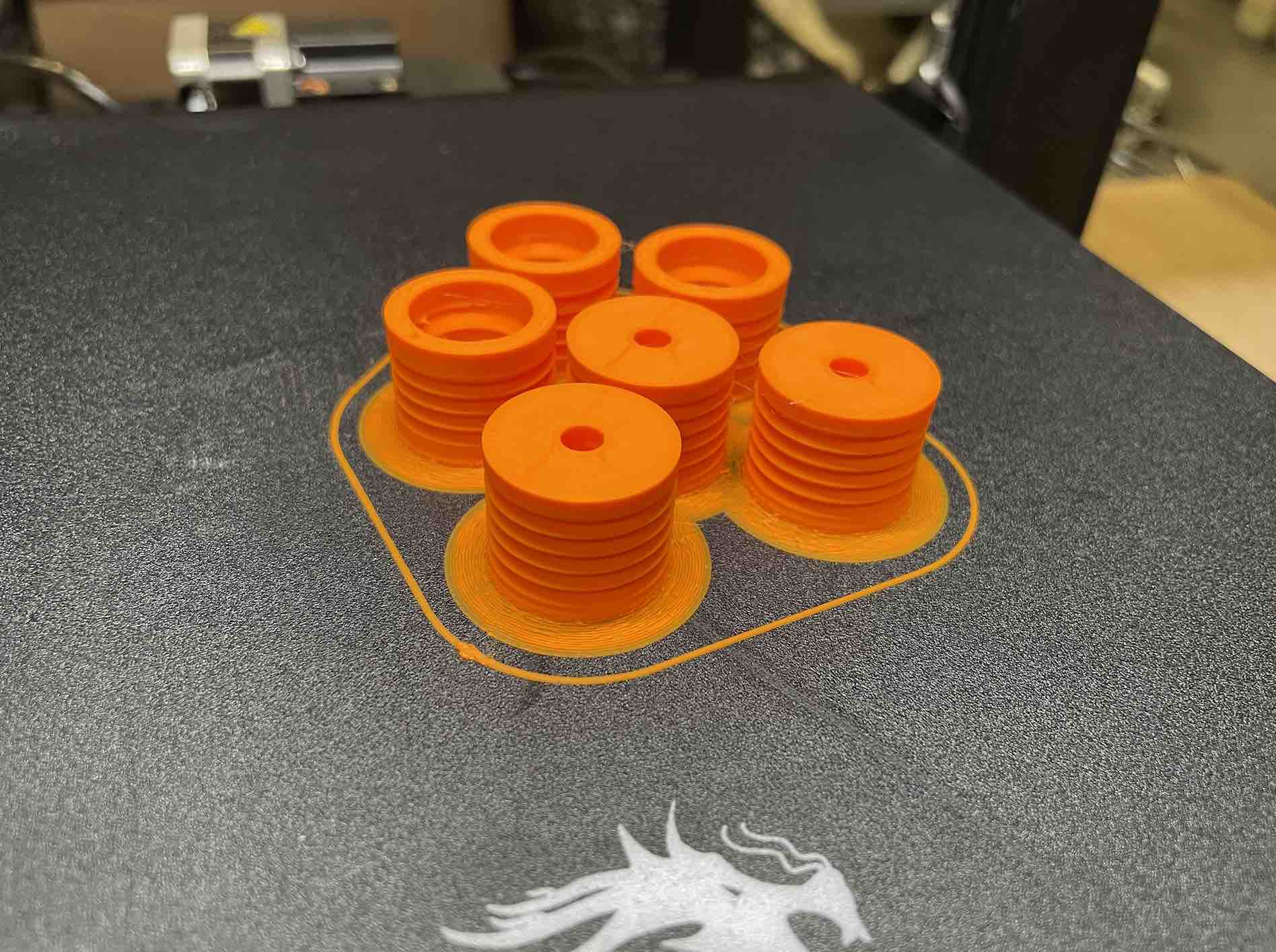
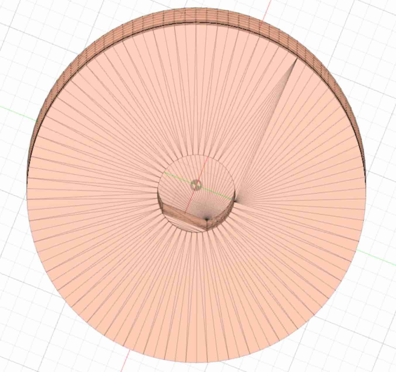
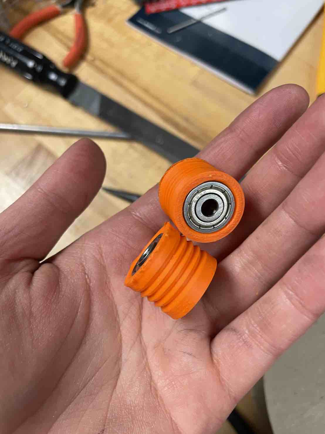
I spent some time printing capstans using the Ender and Prusa 3D printer. In order to get the capstan to fit (the fit was super tight at first and impossible to get the head of the stepper through), I had to use a drill which then made the pieces too loose such that when the steppers were actuated, they would slip up and off. Thus, changes were made in the 3D print to adjust the capstan motor pieces.
Here are a few photos of the capstan prints:
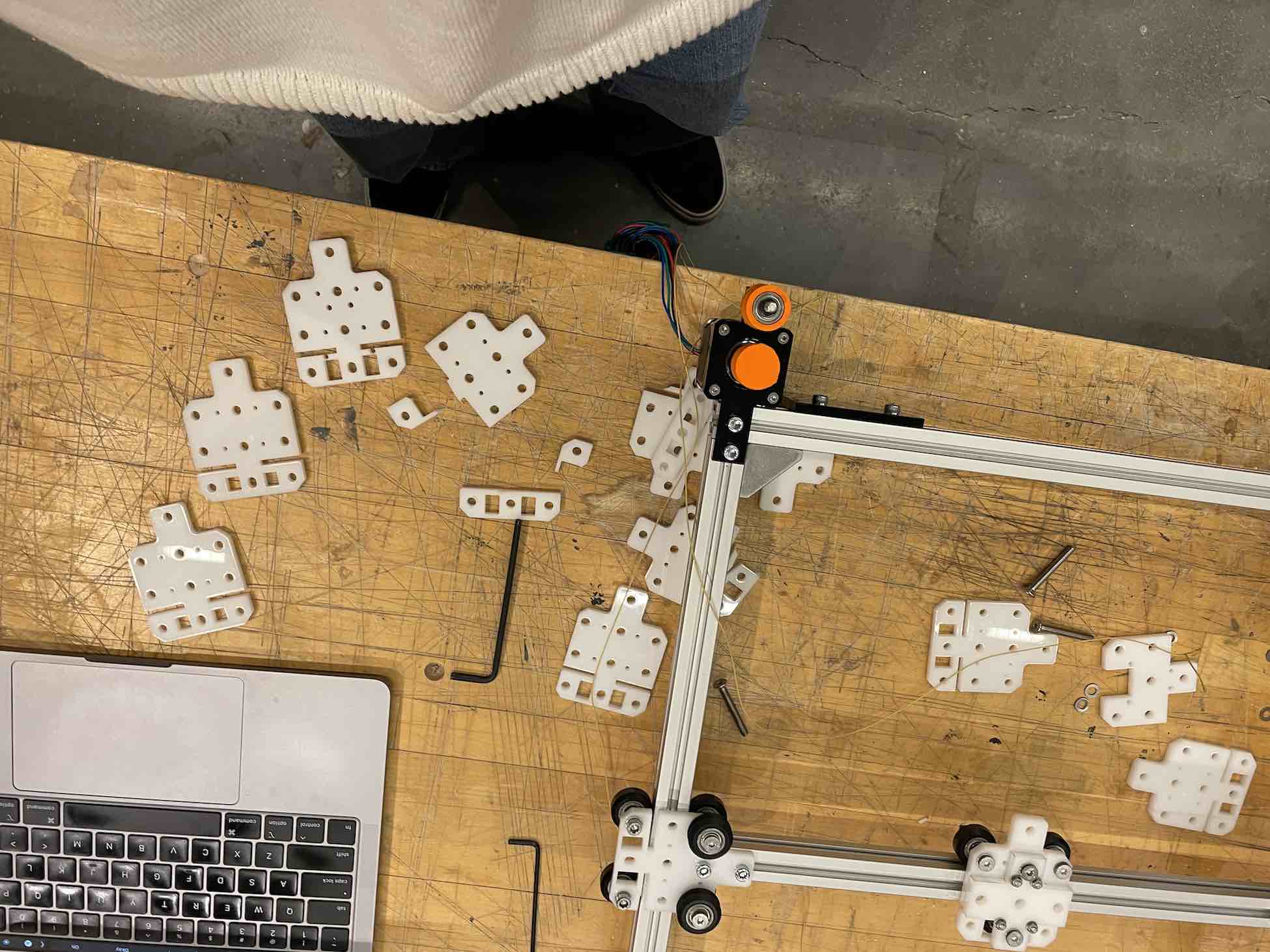
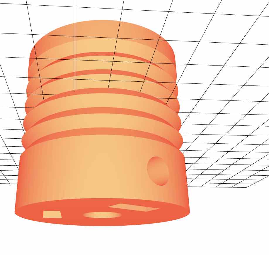
Here are some adjusted 3D printed parts (using our group's Machine Week and Quentin's files):
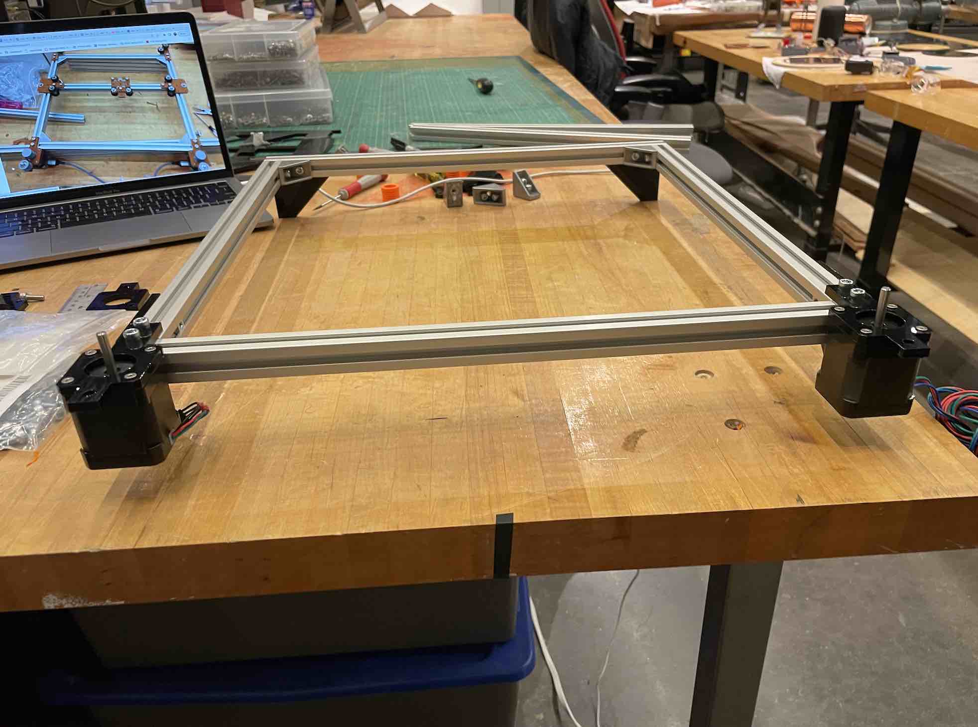
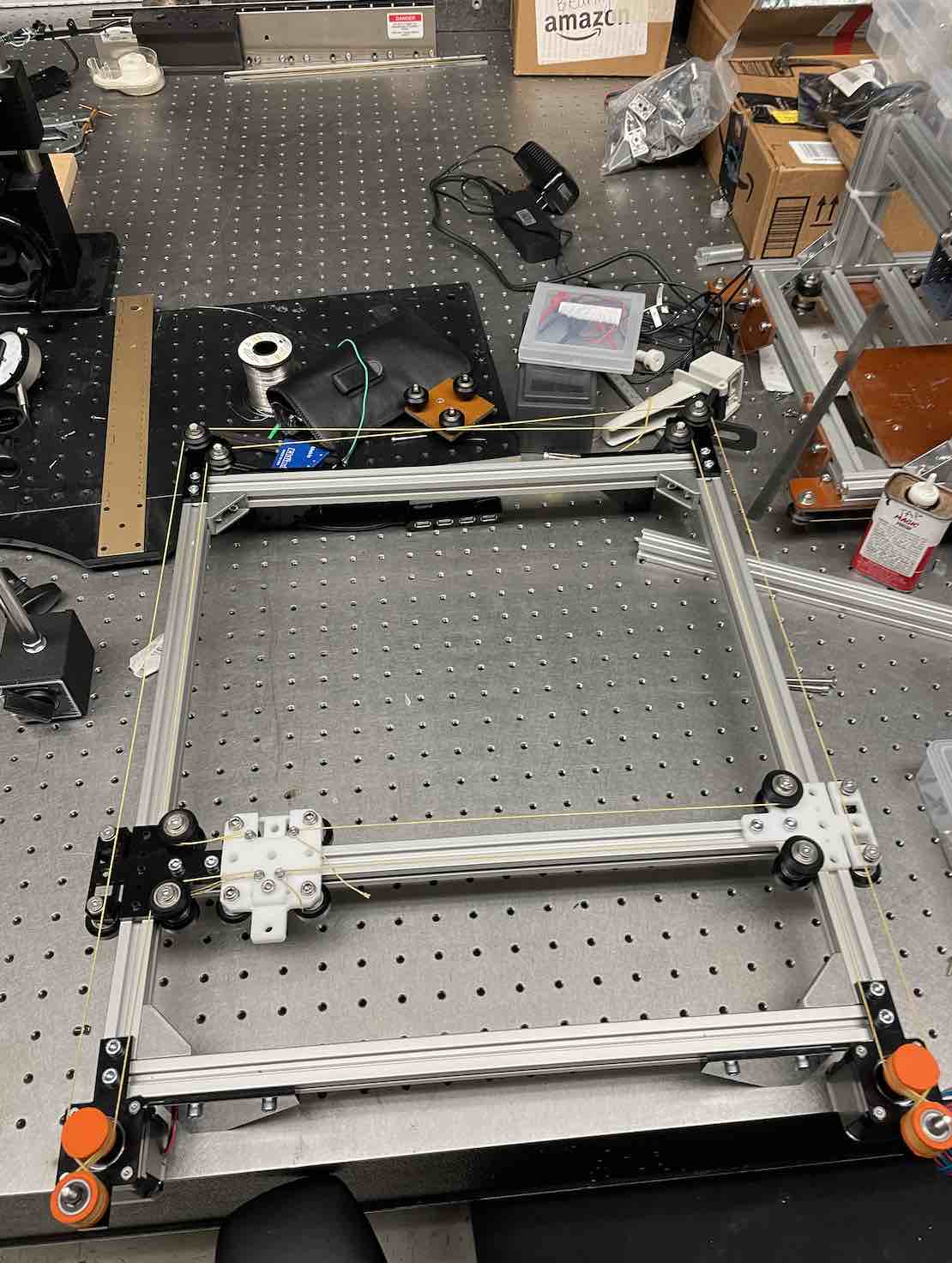
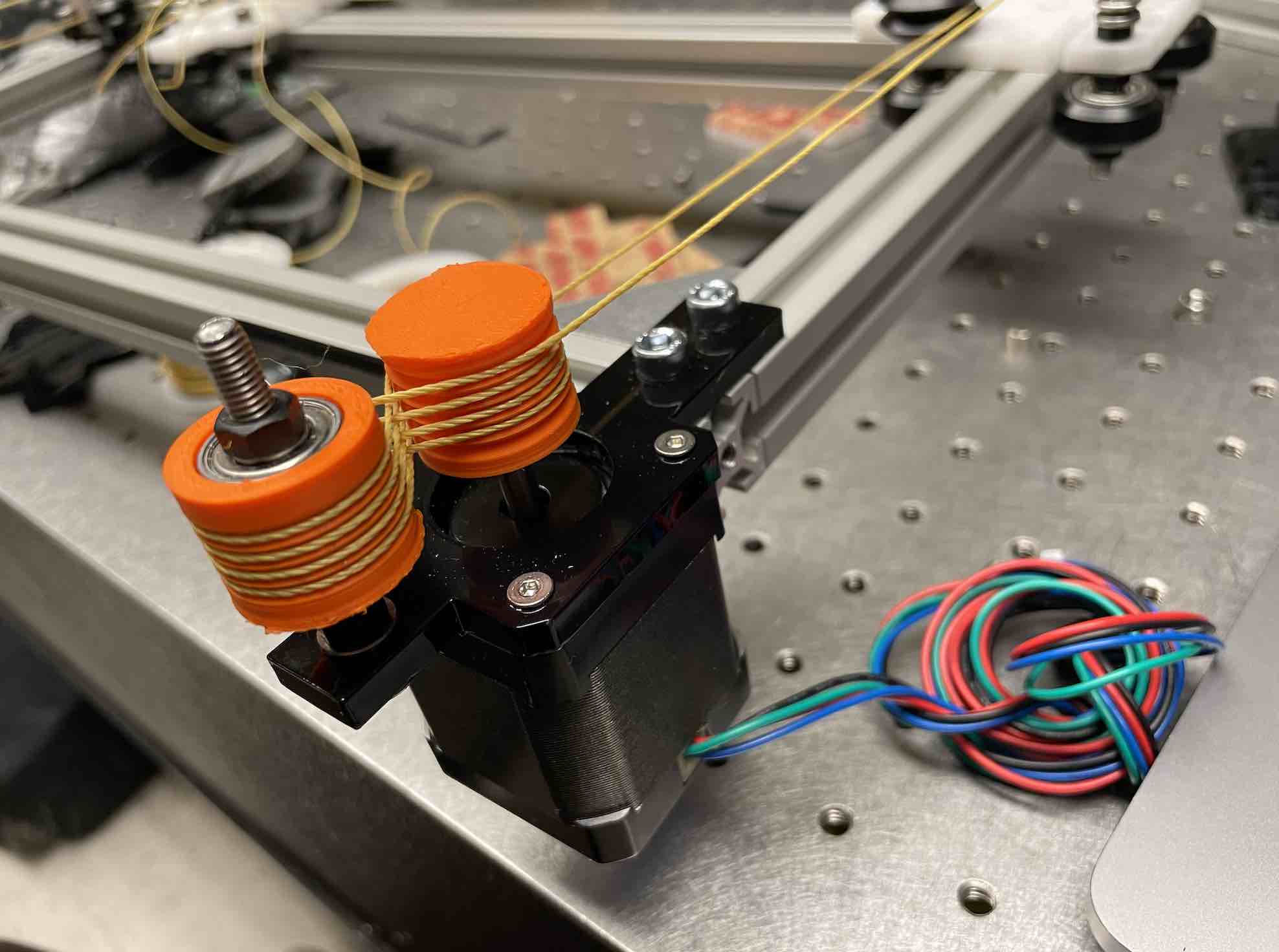
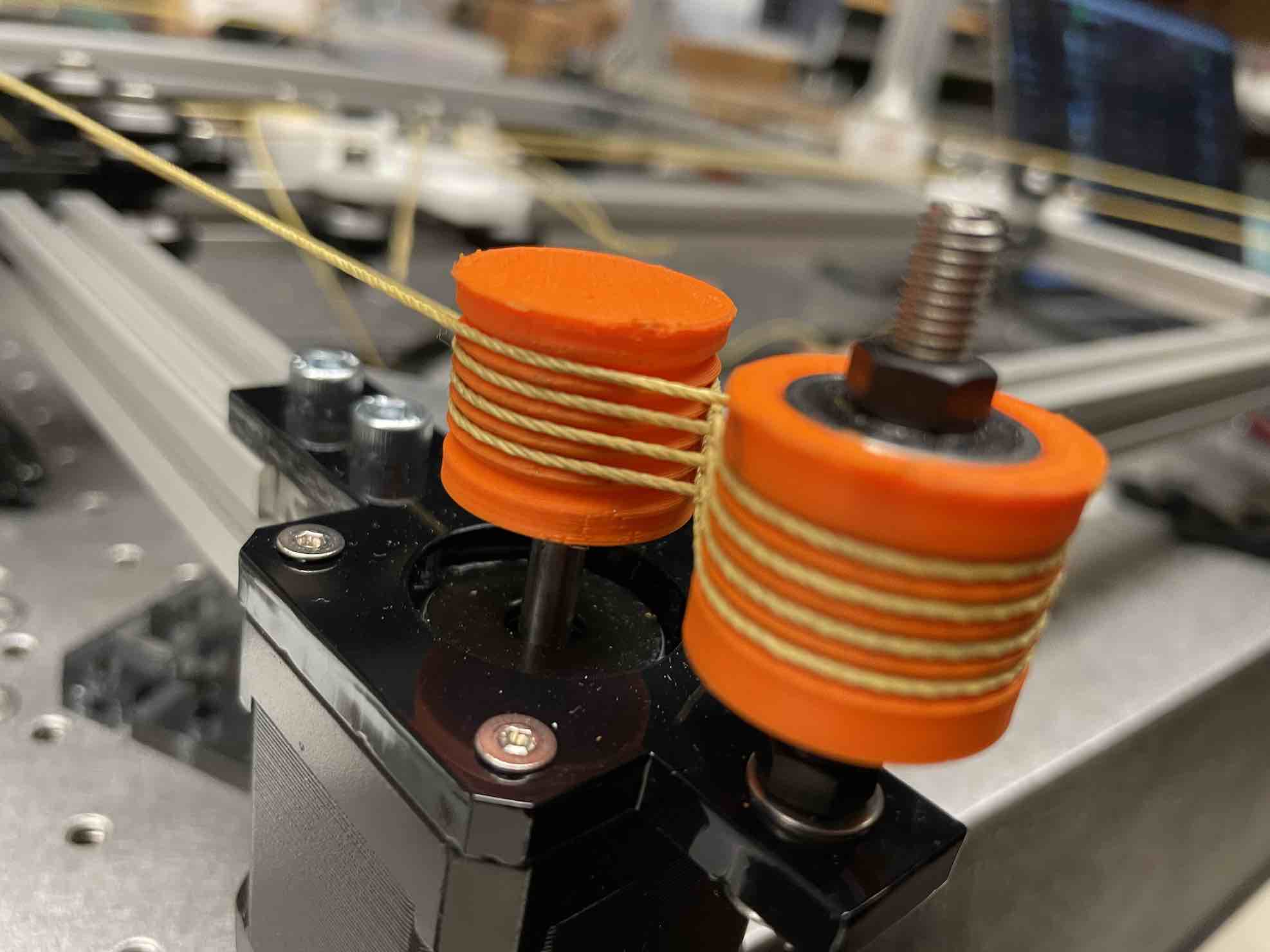
The next step was assembly! This was definitely a much longer process than expected, with lots of adjustments, from assembling the xy frame to creating the bearing chassis/cars that rode through the extrusions (getting smooth movement), to tensioning the Kevlar-enforced string. I spent probably five days (while also working on other subsystems) to get this working to an okay level of smoothness (I even continued to adjust up until a few hours before the demo).
Here are photos from assembling the extrusions:
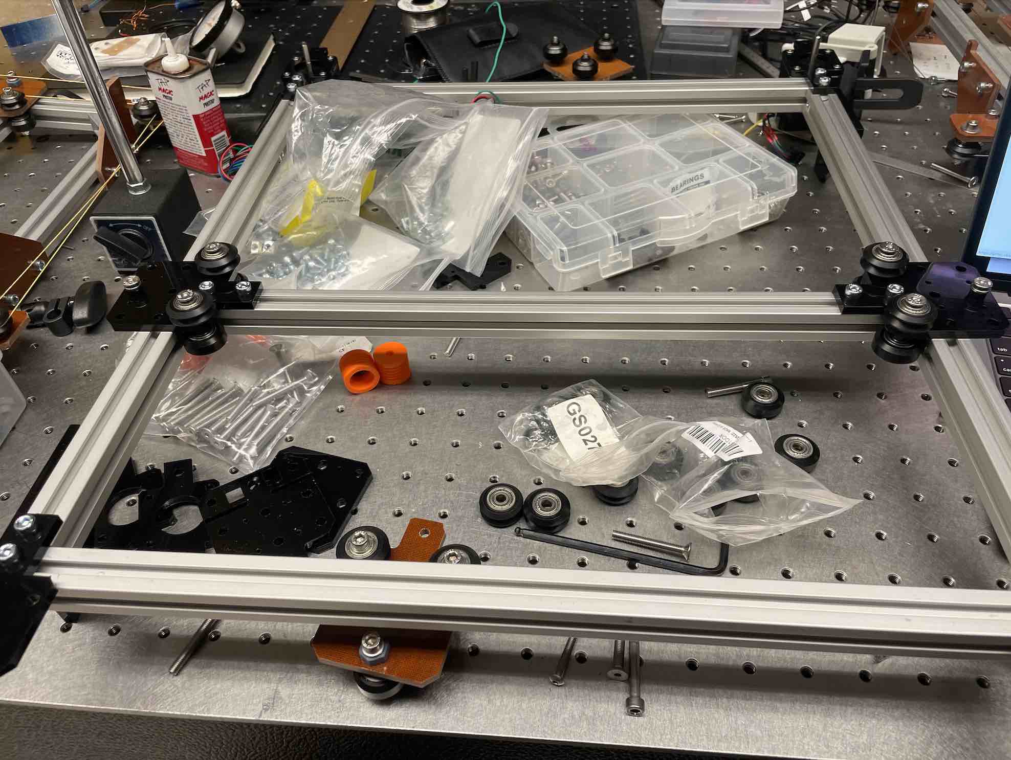
Here are photos from assembling the bearing plates (featuring lots of nuts and screws of all sorts, M2 through M5!):
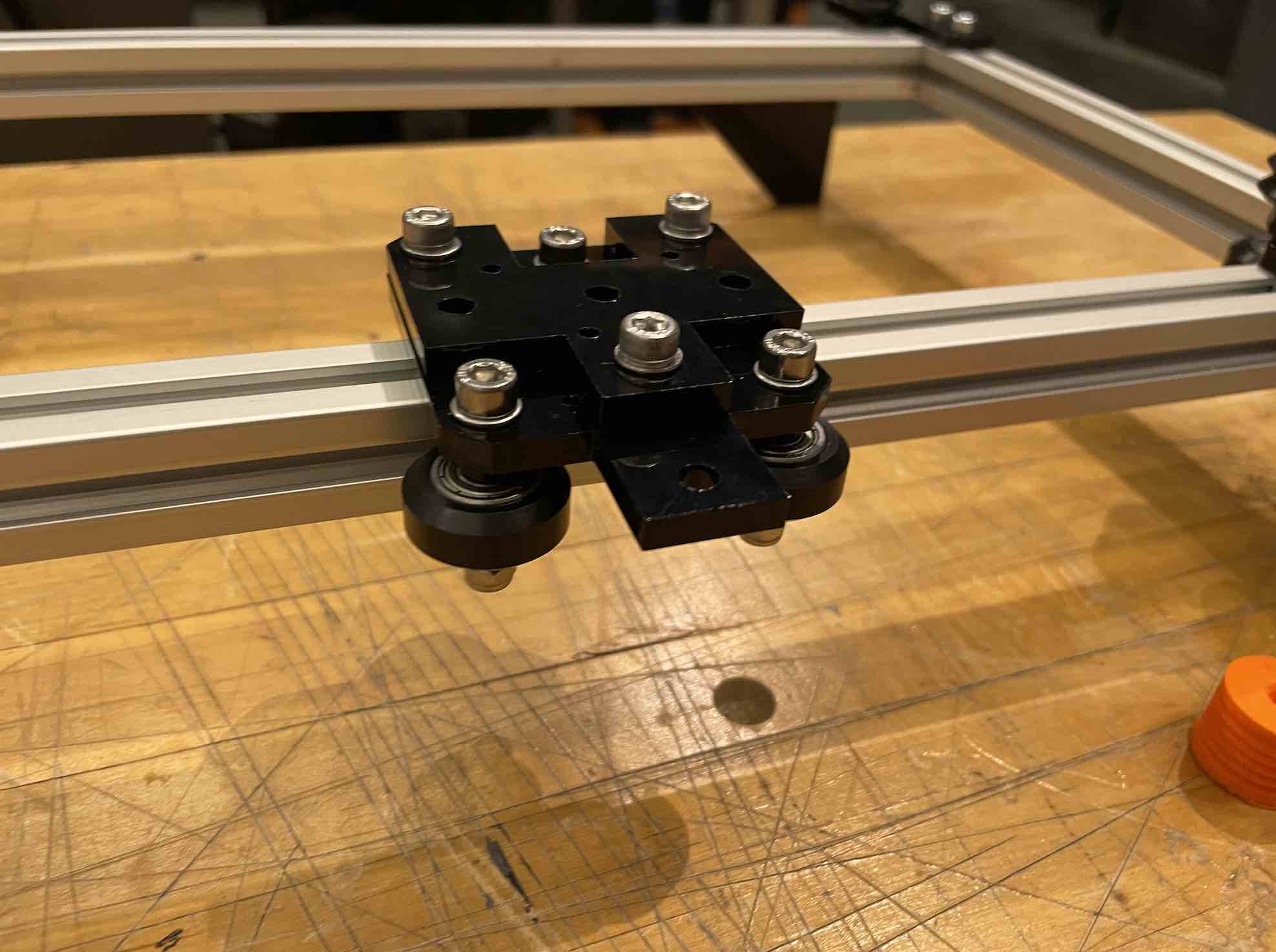
Here are photos from assembling the capstans (using two bearings for each capstan to constrain movement in the z direction), as well as photos from the tensioning process (careful, it can cut your hands!):
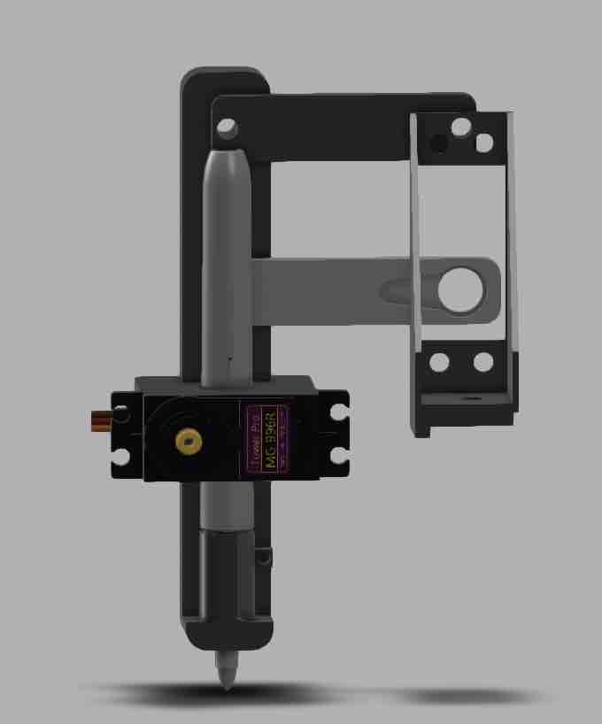
The endefactor was created using the prints from the EECS section (shoutout to Richard who was of tremendous help!):
Electronics
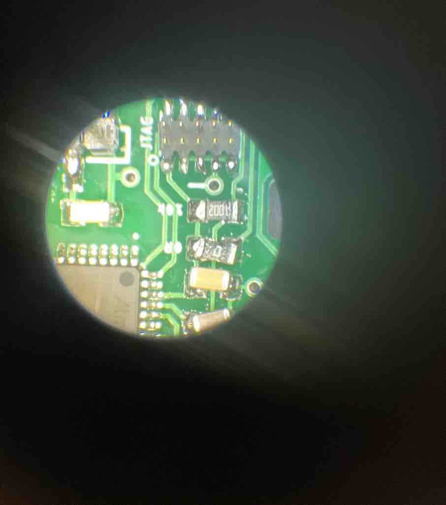
For electronics, I knew I wanted to use the Node JS interface that Jake and Eric had created with modular-things, so I used their modular boards, specifically the ones that could interface easily with the stepper and servos. Using the machine week kit, I was able to use two boards directly for interfacing with the stepper, but I had to stuff a board for the servo. This was also when I discovered (and used for the first time) solder paste, which was useful because SAMD21 had so many pins that it was impossible to get a good solder with just soldering pin by pin with a wide-headed soldering iron.
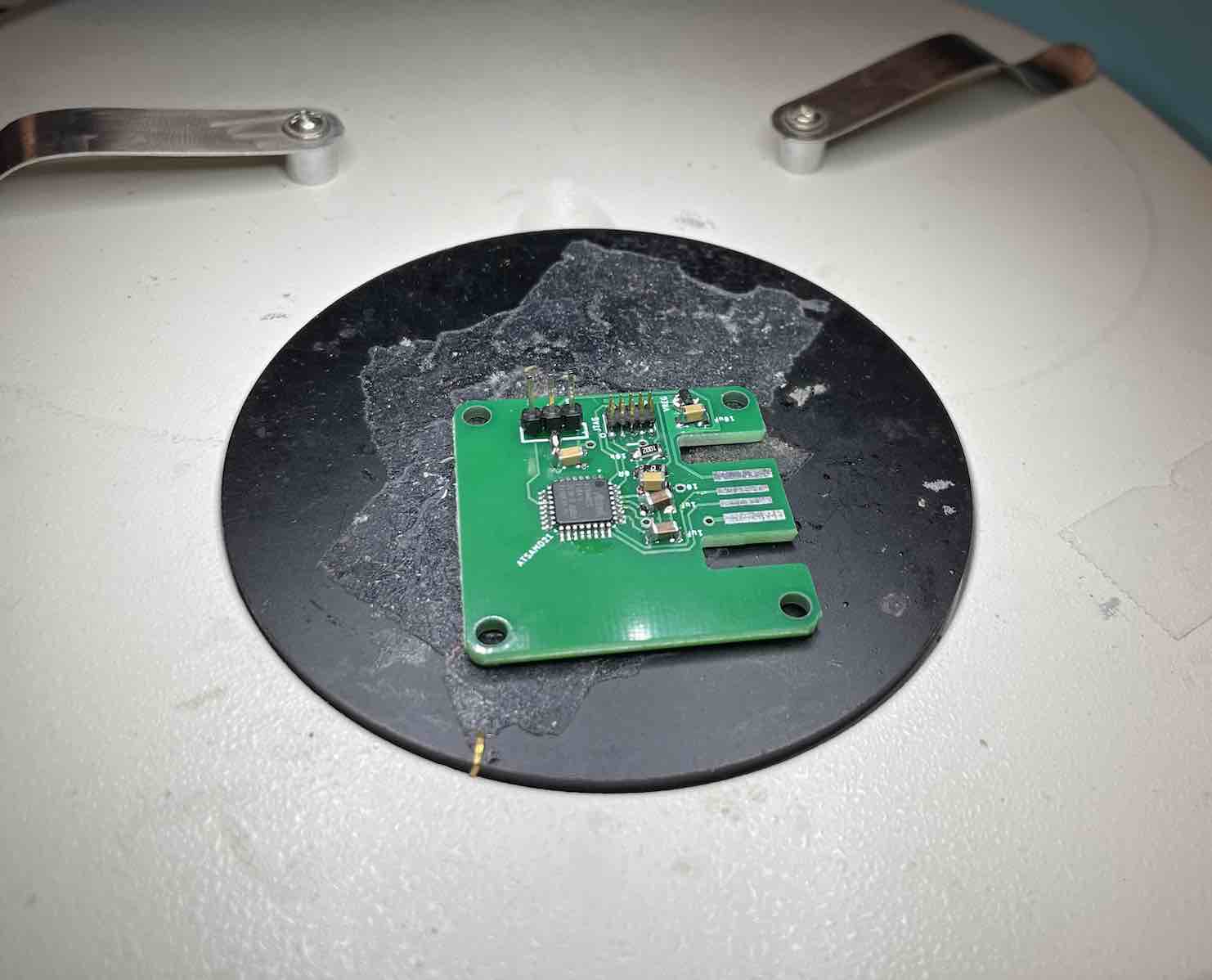
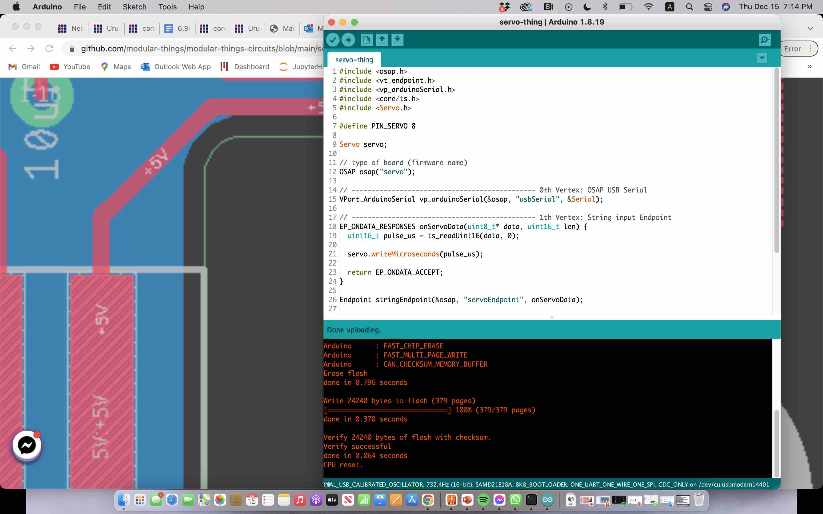
Here is a picture from flashing the board with an Arduino code so that modular-things could recognize the device being plugged in via USB.
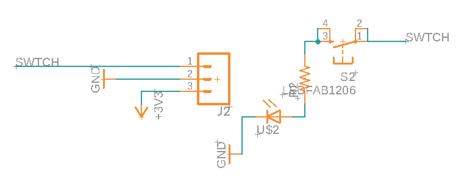
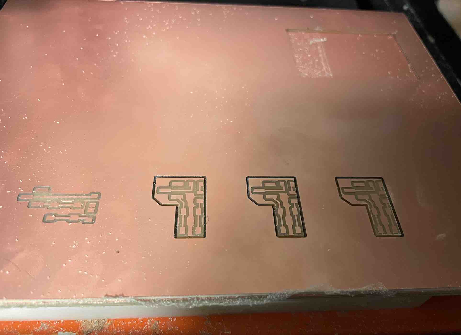
For electronics production, I was intent on creating a small breakout board with a button that could interface with the stepper boards (which already had headers with three pins -- 3.3 V, BTTN, and GND) so that when the endefactor traveled to the edges of the drawing bed, it would push a button and be able to retreat back to home or signal to the firmware side that it had gone too far.
The idea was to also link an LED so that I could visually tell when the button was pushed (on modular-things, when a button is pushed, there is a callback function).
Here is a picture of the circuit and the layout:
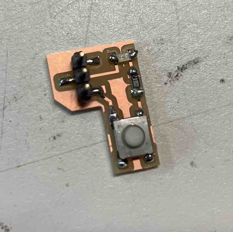
Here is a picture of the milling and stuffing process, as well as a picture of the final board:
I was unfortunately unable to get the LED to interface properly so I ended up scratching these small breakout boards because of limited time and instead making a call "go-home" (essentially) so that the endefactor would start at a uniform spot in the drawing bed each time.
Software
As discussed in interface-week, I tried using an API and HTTP (GET and POST) method with the following architecture, however, I was unable to successfully parse pictures POSTed to the local server. The failed architecture is shown below:
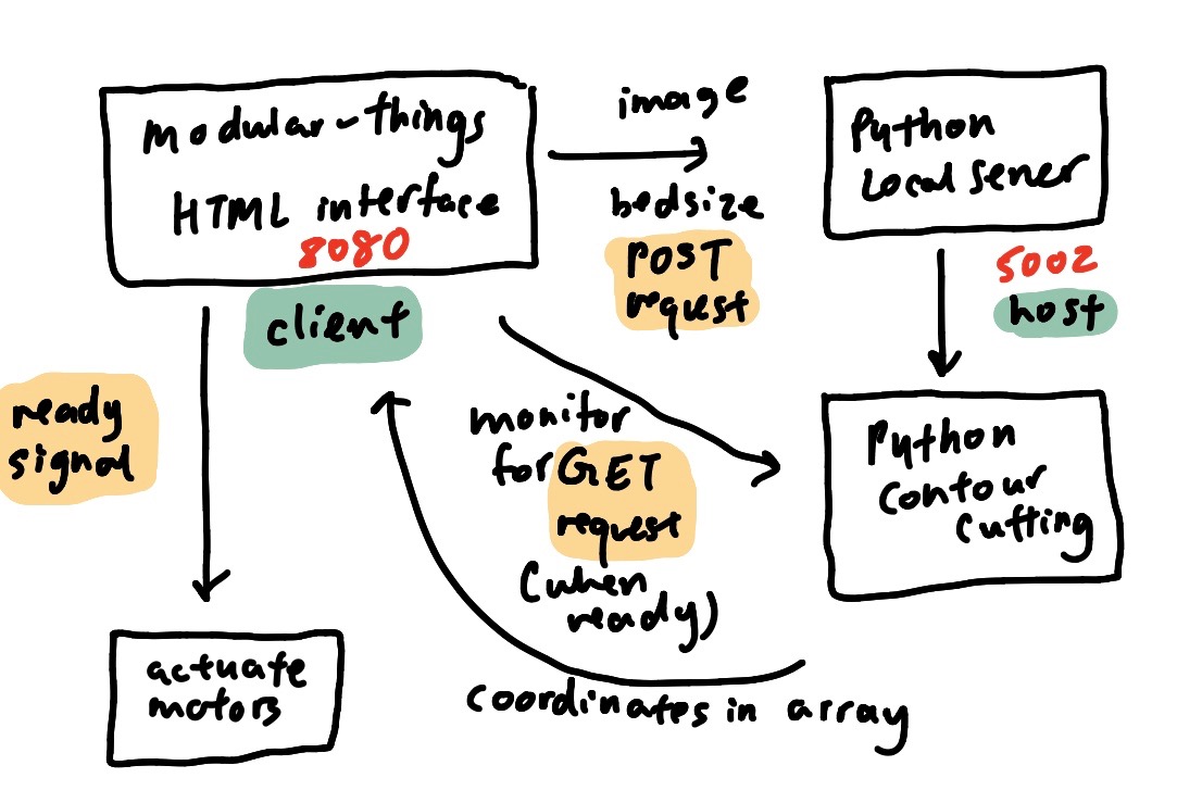
Essentially, on the node js side (through modular things), I could put in HTML and create a stylized interface. This would be a client of a local Python server (basically, when you run the code, you becoming a client of the 5002 local server). Then, when the user is ready to send over the inputted data, they press a button which then creates a POST request to the local server, which is a host to all clients. Through the python script, either by importing another python script or within the same file, it would parse through the POSTed data and then perform contour cutting. Next, the modular_things Node JS interface would monitor the responses to a GET request and when coordinates are available in the form of an array, it can then actuate the motors and draw.
Instead, after discussion with Quentin, we decided that a better (or at least a simpler) approach would be to use WebSockets. The architecture used is shown below:
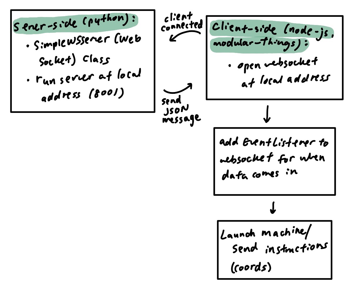
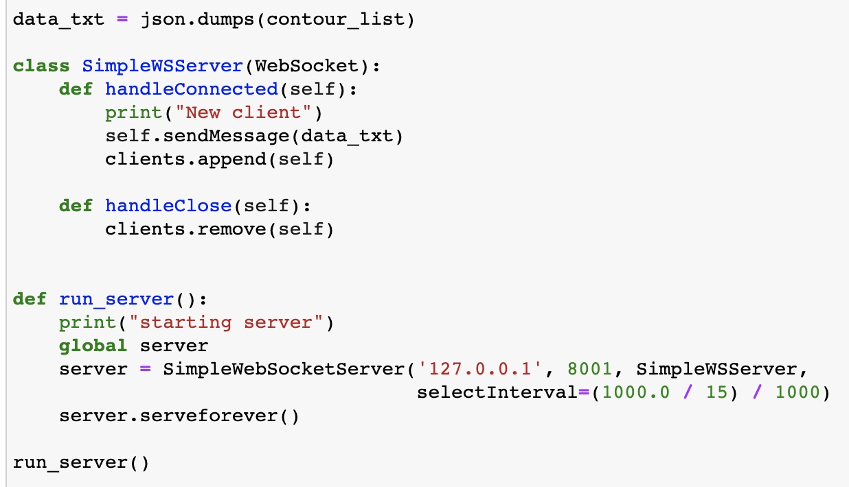
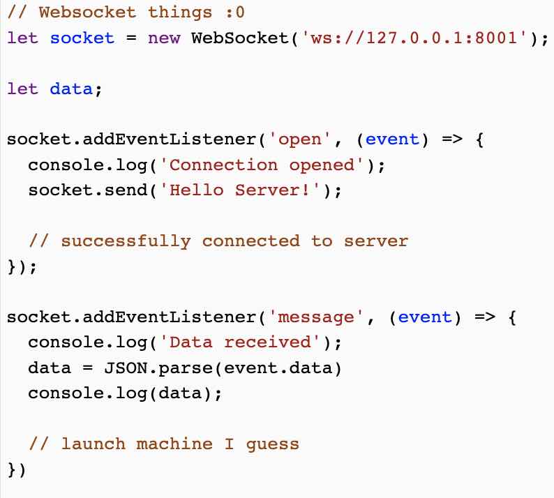
Essentially, on the server side (with python), using a SimpleWSServer Class, functions could be defined for when a client is connected (added) or removed when they access the websocket through the local address that the server is run on. Then, from the client-side (using node-js, modular-things), when I run the script, an instance of the websocket would be run at the local address. Once the client is connected, then on the server-side, the JSON message (encoding the image and instructions for sketching) would be sent. Then, adding an EventListener to the Websocket, we can listen for when data comes in and launch machines/send instructions (through the form of coordinates) to the machine.
Here is the code for my python-side websockets (server):
Here is the code for my modular-things-side websockets (client):
The function for creating vectors and coordinate instructions (in the form of nested arrays) from inputted images was implemented on the server-side both because I am more comfortable with python and because we are unable to import some useful libraries on the Node JS side.
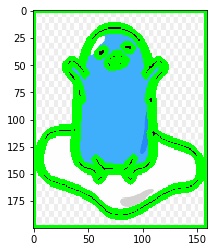
The first step was to minimize the images based on the maximum dimensions (x,y) of the drawing bed. Then, contours could be generated by making the images into greyscale, setting a black-white threshold for detection, and then using opencv to generate contours.
Here are photos for the animated character Gudetama (a Japanese egg) undergoing this image process and contour generation:
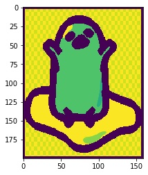
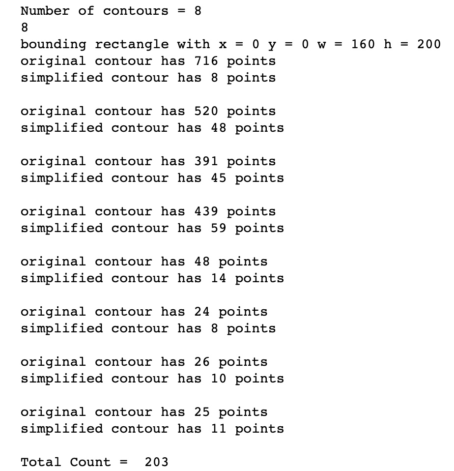
Something I found interesting was the simplification of contours. Oftentimes, contours generated using opencv would have hundreds of points (many of these points directly adjacent one another or in a horizontal line but made up of many redundant points). Thus, I imported a library where I could very easily simplify contours through the Ramer–Douglas–Peucker algorithm. For RDP, I initially tried values varying from 0.1, 0.01, 0.001, and eventually found that a sensible epsilon value was 1 for the purposes of my implementation. Through this step, I was able to minimize from hundreds of points at times to less than 30! This meant that my machine could not only run smoother but also take less time by making larger steps as opposed to an accumulation of small steps.
Here are the reduced points results from simplifying contours! A big difference was found :) :
Testing and Presentation
There were lots of small and big milestones throughout the course of the project. The first milestone was drawing a circle (which my friends got to witness on the 3rd floor of the Media Lab fueled by French Vanilla Coffee -- from the kitchenette next door -- at 2 am). Woohoo!
The next milestone was getting the coordinates for a picture sent over the Websocket, in which case it began drawing (but without the endefactor moving up and down, so all contours were contiguous -- something that would be solved with the next milestone of installing the endefactor)
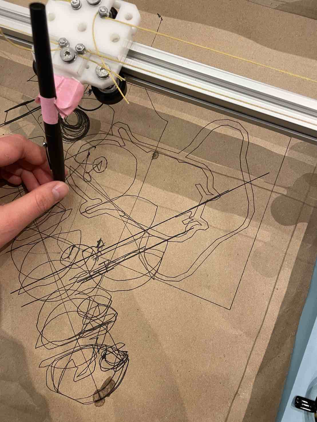
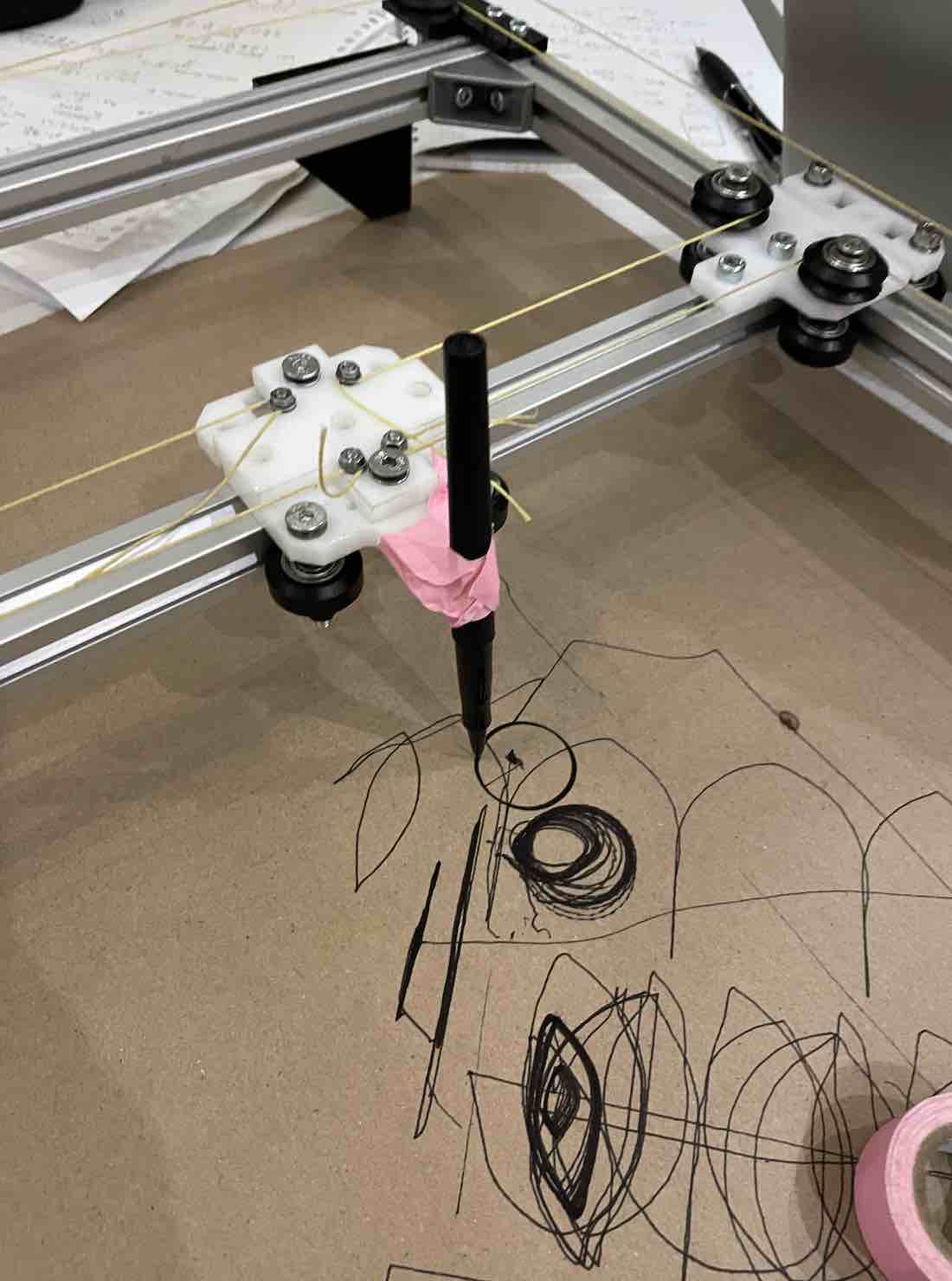
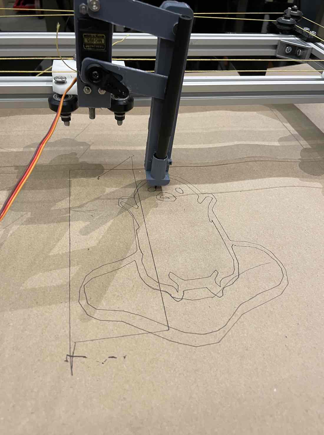
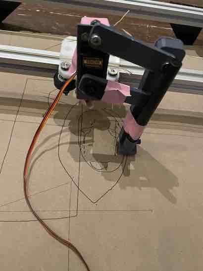
With the servo for the endefactor installed, the pen was able to move up and down, allowing for non contiguous contours:
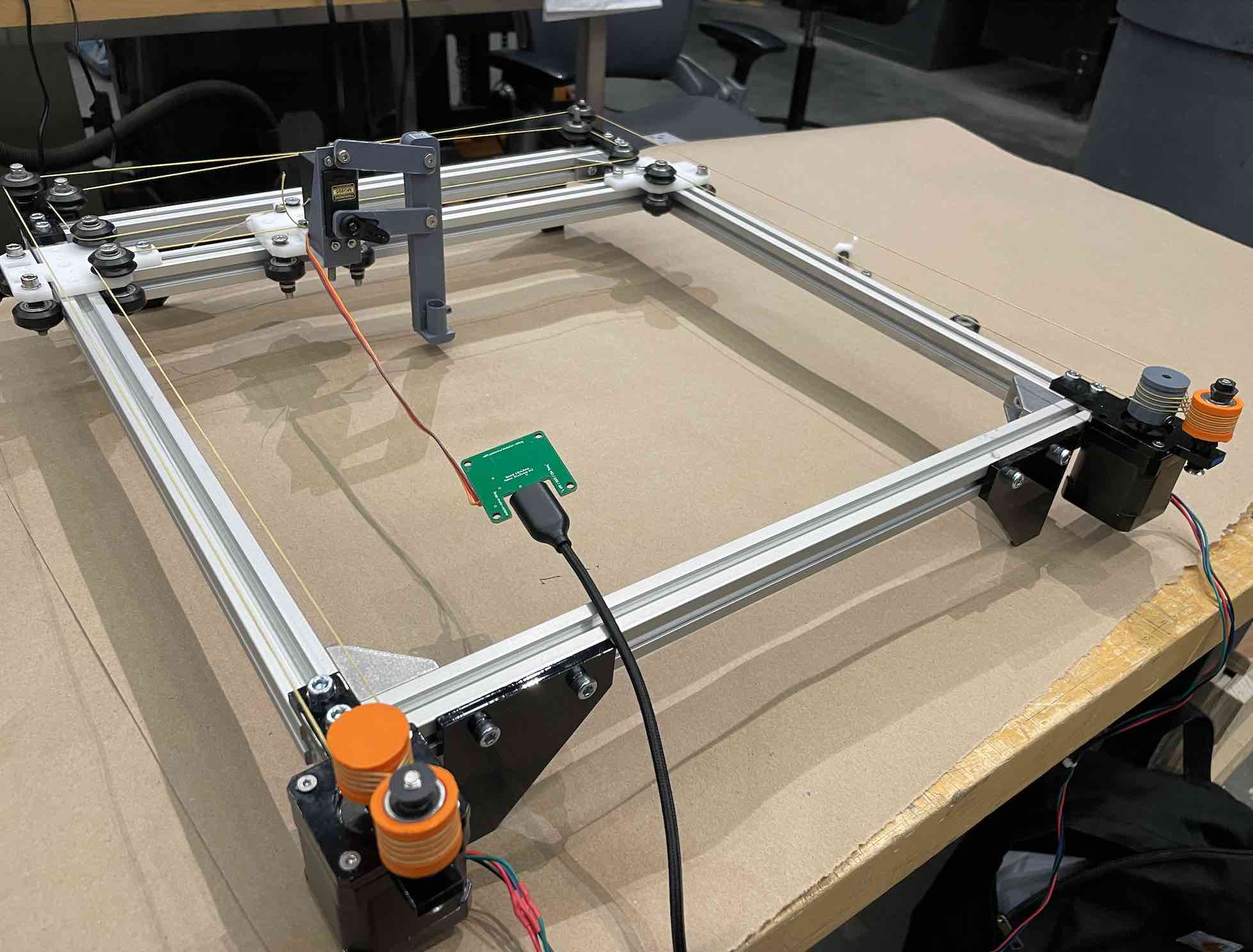
This is a picture of the final assembled machine:
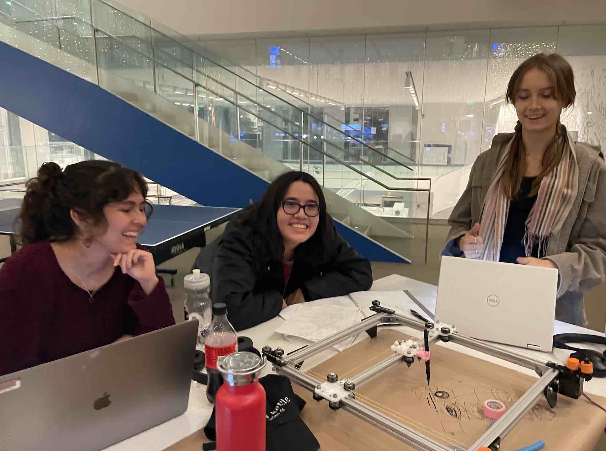
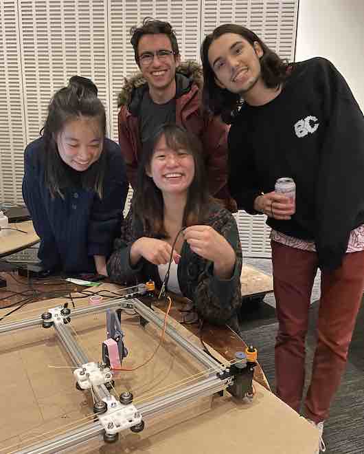
These are a few photos from demo day/final presentations! My friends came to visit and it was also so fun to let people passing by draw pictures. It's always fascinating to see a machine sketch :)
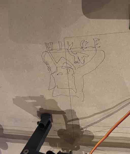
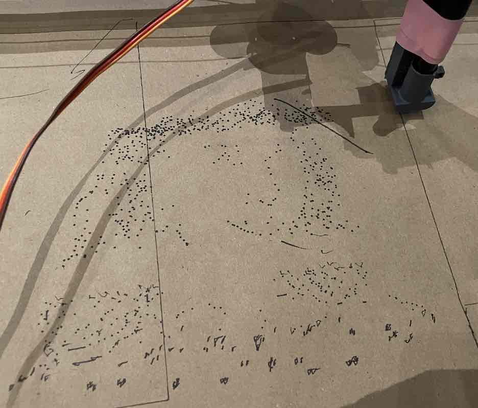
Something interesting that we discovered during the demos and open house was the ability of the machine to replicate images from single points (something I learned was called pointillism that we accidentally achieved through loading in images with delicate shading that created contours that were very tight):
There are certainly lots of valuable next steps to take with this project. A few of which include: better constraining the endefactor, creating an endefactor that can hold and select from multiple sharpies/colors, creating an interface for loading in images, creating an interface for loading in videos where the software can then select frames within the video and draw multiple frames on a single bed, creating a roller mechanism for the paper so that the machine can continuously draw on fresh paper, the list continues -- essentially, create a full blown flipbook machine! This was only the first spiral and I definitely want to continue this project in the future.
Overall, this semester has been so rewarding. Thank you so much to the shop managers, Tom and John, the TAs (so many with so much rich knowledge. Just to name a few, Quentin and Miana), Neil, and my classmates (shoutout to the CBA section!!) who have made this an unforgettable experience.
As Neil often says, "the class starts when this course ends!" To an exciting, new beginning.