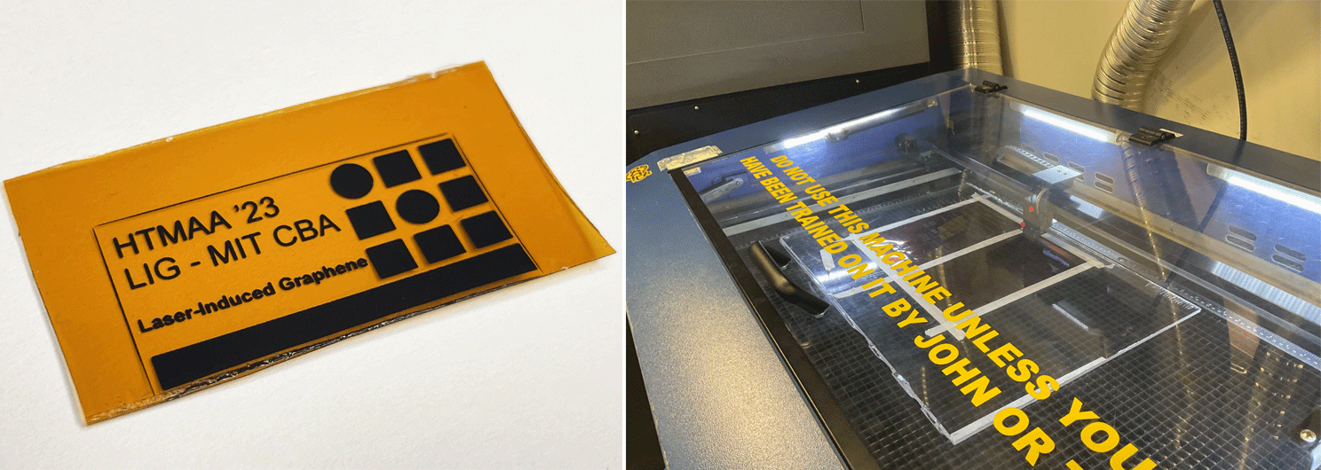
Tools: GCC CO2 laser
Laser-Induced Graphene (LIG) Fabrication Process using GCC Laser @ CBA
This page documents the process of producing laser-induced graphene, in general, but also specifically using the GCC Spirit 30W 10.6 microns CO2 Laser at MIT CBA .
Introduction !
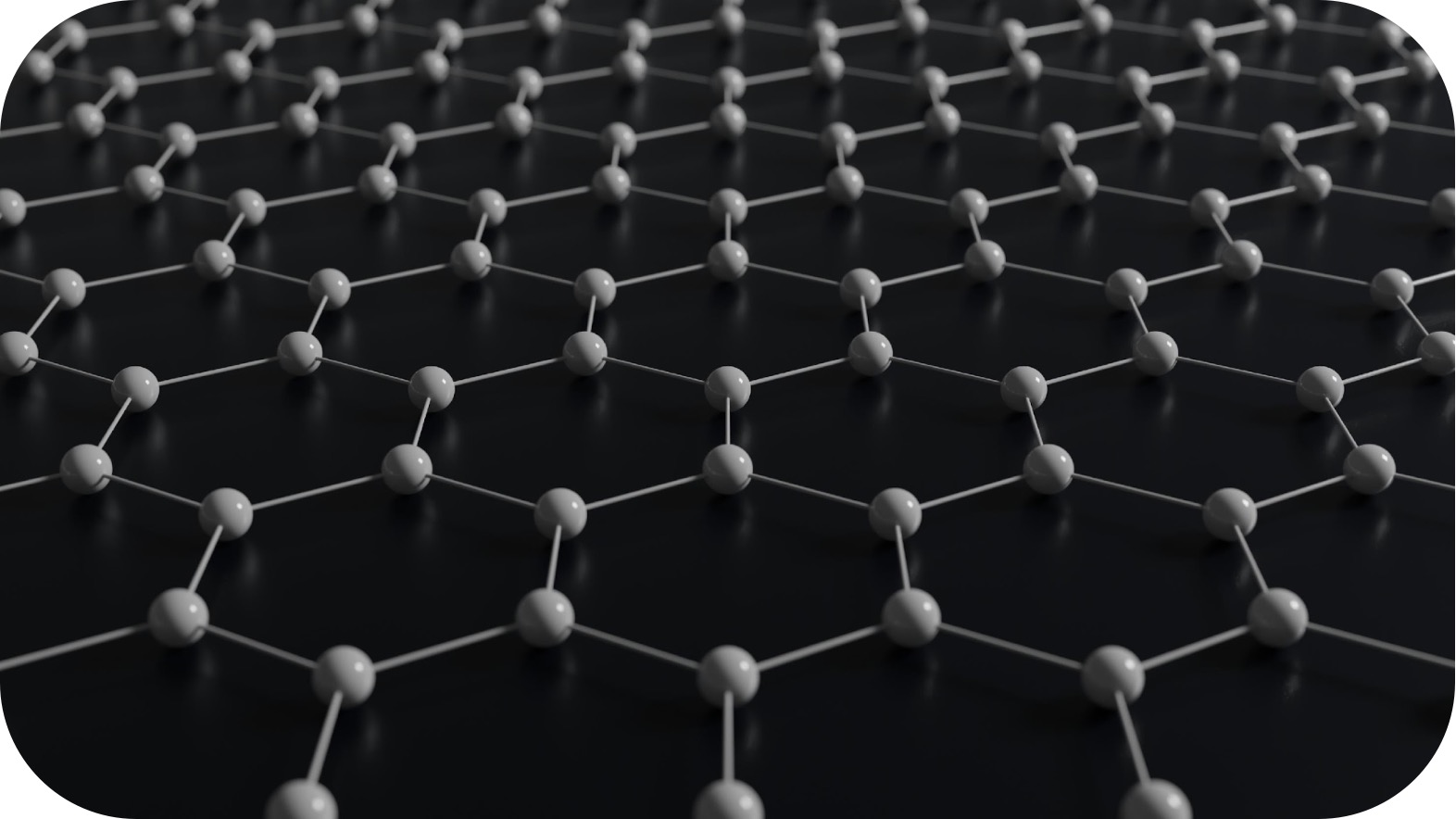
You might have heard of graphene , a wondrous material discovered in 2004 that was promised to save the world because it has a lot of really interesting properties. It has shown promise in everything from solar panels to thermal compounds energy storage to composites, biosensors, and others.
The difficulty is scaling up these graphene processes and their integration within existing fabrication processes! Producing high-quality single monolayer graphene requires advanced tools such as chemical vapor deposition (CVD) tools that you can find at MIT.nano, but today we are not doing this. I am going to introduce you to a type of graphene known as laser-induced graphene (LIG).
What is Laser Induced Graphene (LIG)? !
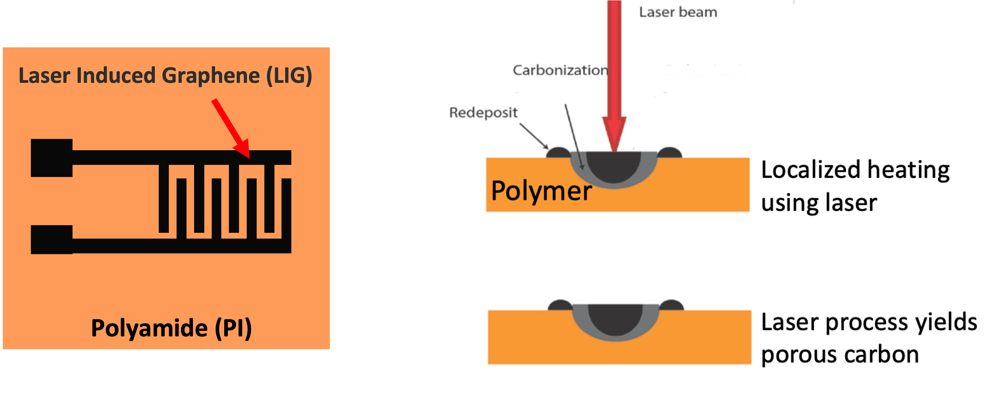
In 2014, researchers found that hitting a polyimide (Kapton) sheet with a CO2 laser will make it decompose into a graphitic substance! Upon further investigation, this graphitic carbon-based substance turns out to be a type of graphene named laser-induced graphene (LIG).
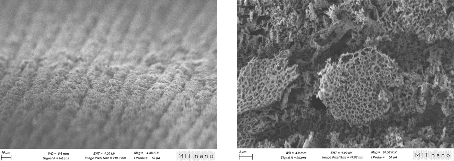
This forms a porous structure of foamy carbon wonder material!
This is very different from the monolayer graphene that you typically hear about, and it has some interesting properties relative to the monolayer.
History: Actually, the very first report of generating conductive material by irradiating a polymer with a laser dates back to 1991 when Schumann et al showed here and here but this was not LIG per se. The very first LIG was shown in this Nat. Commun paper by Tour’s group.
Properties of LIG
The cool thing is that you are using a laser, so you can pretty precisely pattern where you want that graphene to go!
Fabrication Process of LIG
Now that we have discussed why LIG is a cool material let’s talk about how you can make your own LIG for your applications! The process is quite simple, you just need a piece of Kapton sheet and your favorite laser cutter!
1. Starting with Carbon-rich Materials: Polyimide (specifically Kapton is commonly used. Note: Although Kapton is the most commonly used substrate, people have used other materials that include carbon precursors such as cloth, paper cardboard, and even food! (More here!) & Bio-LIG
2. Laser Irradiation: A focused laser beam is directed onto the polyimide. The intense heat from the laser triggers a reaction in the material.
3.Transformation into Graphene: The carbon atoms in the polyimide rearrange into a graphene structure. This form of graphene is porous and three-dimensional, unlike traditional flat monolayer graphene sheets. Note: In fact, you do not need a CO2 laser, the first report of LIG happened to be using a CO2 laser, but you can use UV, 405 nm, 450 nm laser diodes -- > ( I built a machine named lazerGraph based on Creality inexpensive laser module )

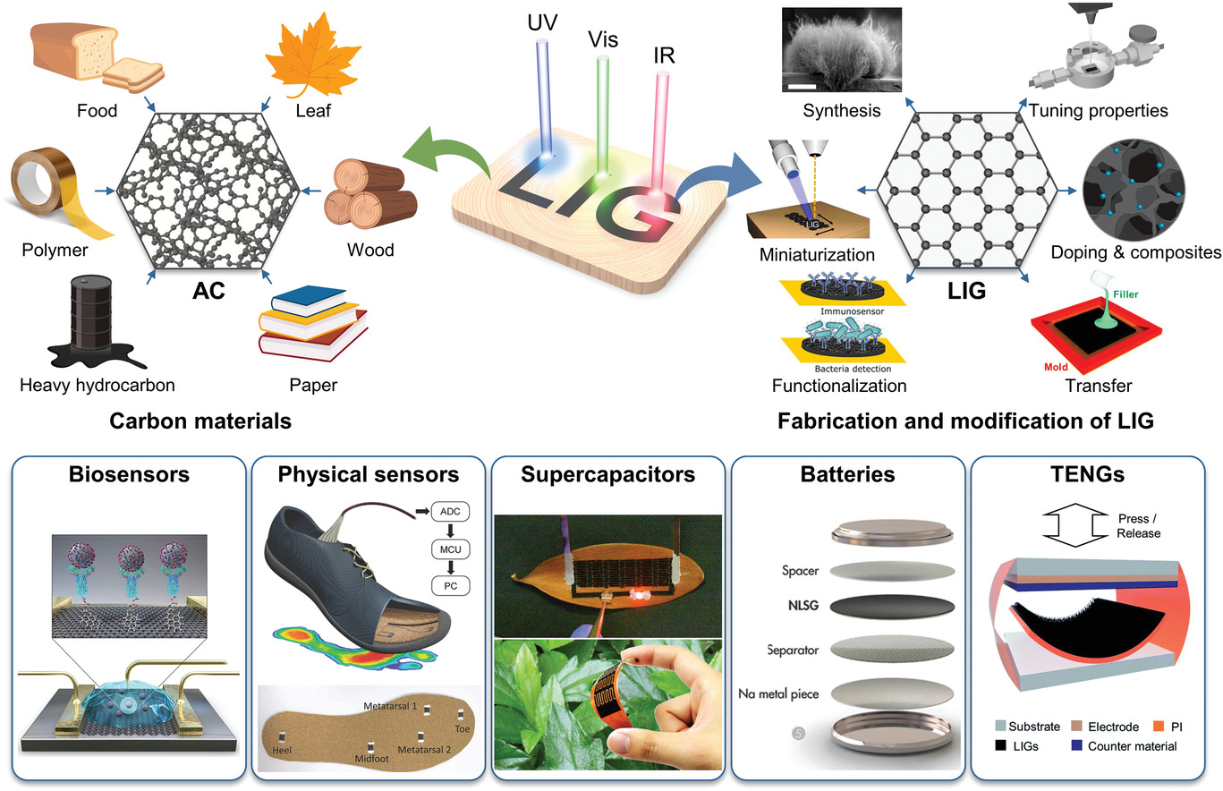
Applications of LIG
LIG's unique properties allow for its use in numerous fields: (Nice Review)
The cool thing is that you are using a laser, so you can pretty precisely pattern where you want that graphene to go!
Demos
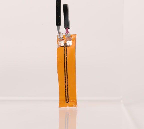
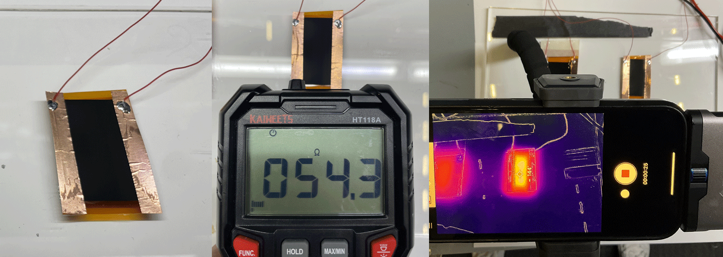
Strain bend sensor --> my HTMAA input week assignment
heater
LIG at CBA Shop
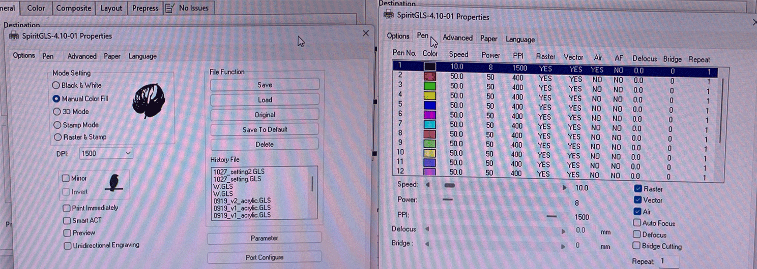
(LIG fabrication is all about finding the optimal parameter (power,speed,PPI) for your own laser tool !)
General Notes:
Current parameters
Notes:
Some Issues !
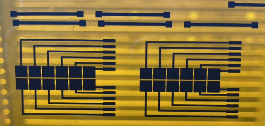
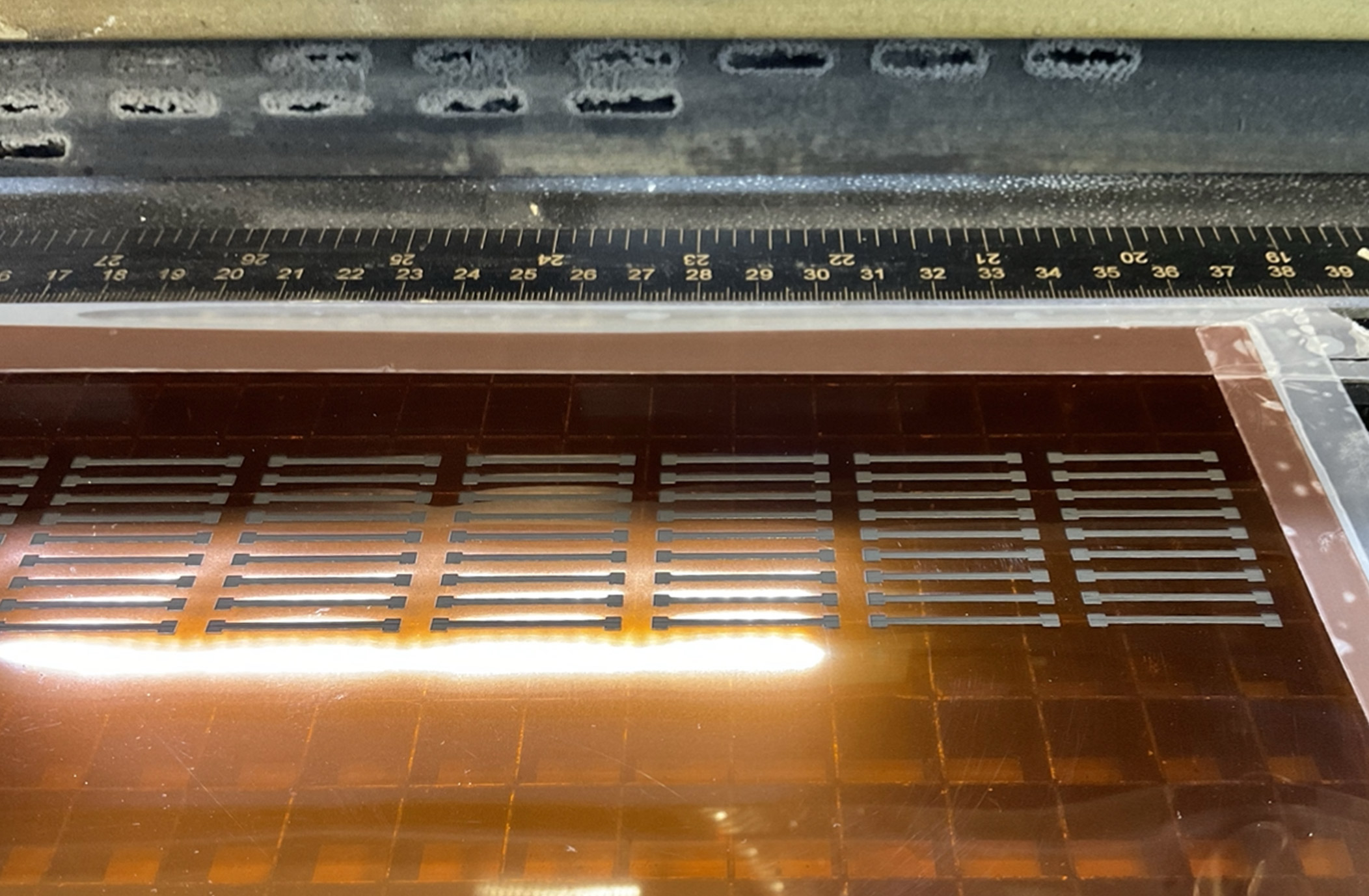
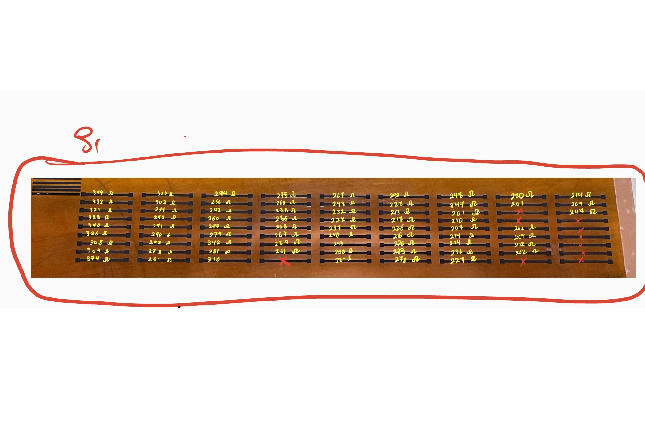
After fixing the laser setting parameters above, I decided to laser-scribe an array of 81 electrodes with an identical length (22 mm) and width (2mm) each. The idea was to measure the resistance of each generated electrode in order to test the consistency of the process.
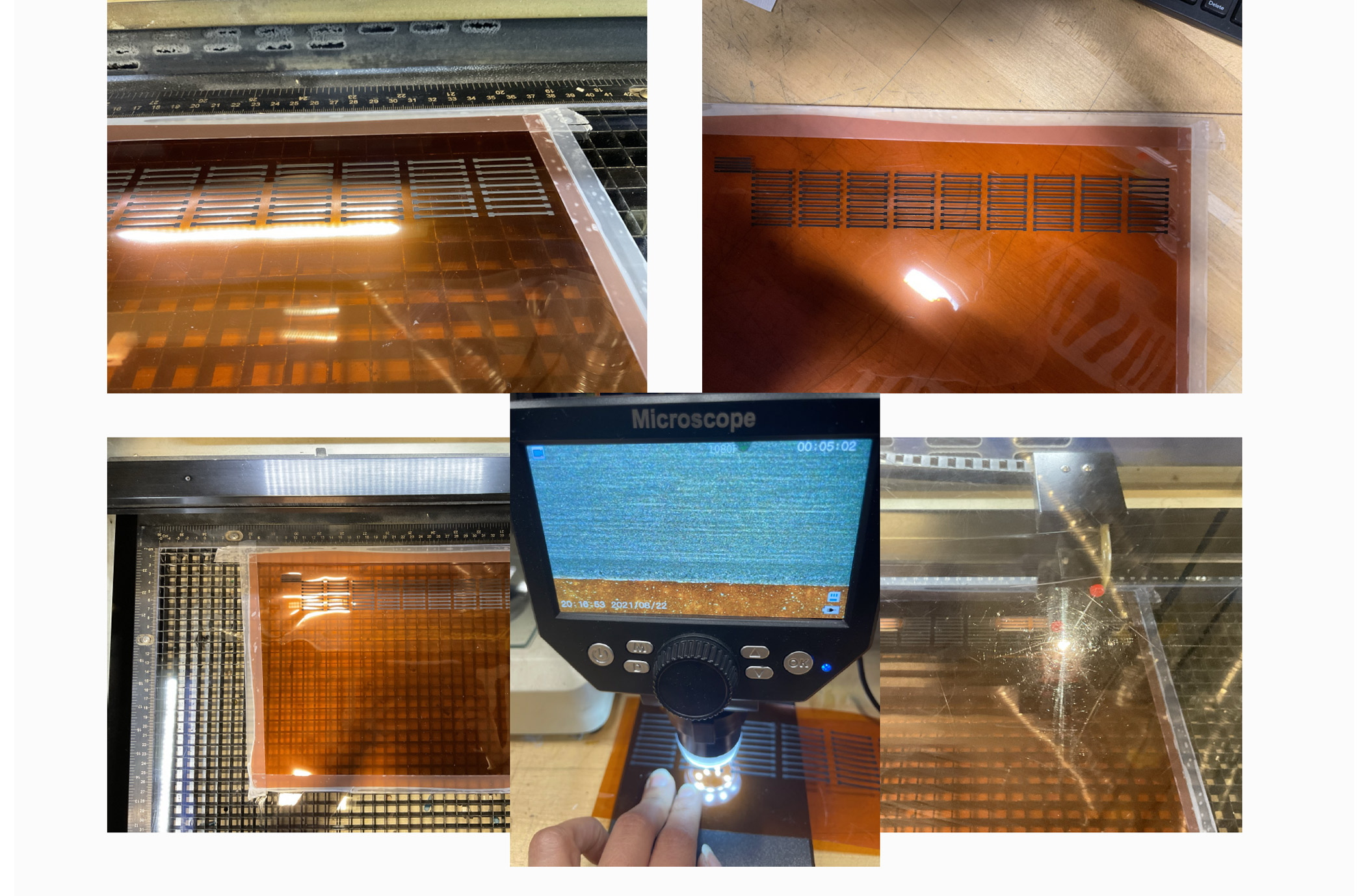
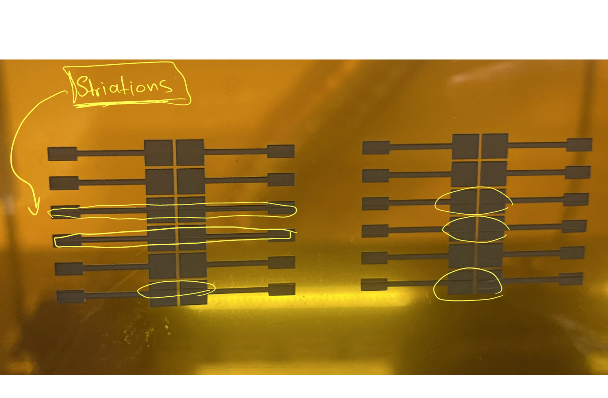
For the most part, the majority of the electrodes looked visually the same. However, when I took a closer look, I found that some electrodes had some striation patterns that are repeated. This might indicate some defects in the laser engraving paths.
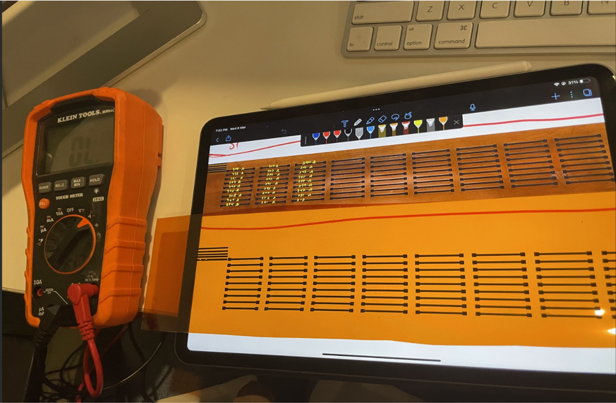
Measuring variabilities
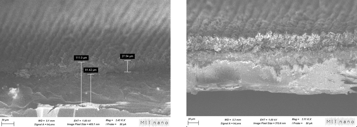
Most importantly, the resistance readings of the electrodes show measured resistance readings as high as 374 Ω to as low as 201 Ω for electrodes of the same length and width! Having fixed all other parameters leaves us with the z height as the main parameter that might be changing from one sample to another. Testing the z bed leveling with the manually focusing tool across different bed areas confirmed that there is variability in height. Although these variations are in the mm range, their effect on the graphene generation process is pronounced since the generated graphene layers are in the micrometer range.
Some electrodes actually had too many striations to the point where the electrodes were completely broken. Those electrodes are marked in red below
Next steps