Tools: Fusion 360, MODS, EDGB, PCB Milling (SRM-20), Soldering, Arduino IDE
Flexible Sensors
This week is all about input devices and basically trying to sense all kinds of things going on in the world around us! Given my interest in flexible and soft electronics, I decided to fabricate my own flexible sensors base on functional materials that I have worked with before, such as laser-induced graphene (LIG) and Gallium Indium eutectic liquid metal (LM). I decided to make two sensors: one would utilize the resistive sensing mechanism, and the other would use the capacitive sensing mechanism, two of the most common sensing mechanisms.
For the microcontroller boards, I collaborated with Ozgun to create two PCBs, one for sensing and one for capacitive, which we can use with our fabricated sensors!
Flex Bend Sensor - Laser Induced Graphene (LIG)
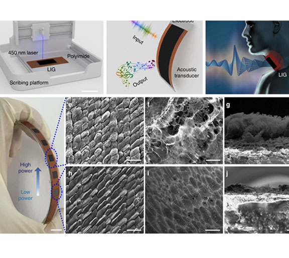
For the resistive sensor, I decided to use laser-induced graphene as the sensing material that makes my sensing elemnt. I have experience working with laser-induced graphene (LIG) before for motion sensing, so I decided to re-purpose my skills to make a flex LIG sensor that can measure bend angles. I got inspired by this article , published in nature communications, where they used a resistive LIG sensor to detect small throat vibrations such as hum, cough and scream with different intensities or frequencies! Additionally LIG has a nice range of resistance values which I think can be read easily by a voltage divider circuit without the need for extra amplification or filtering.
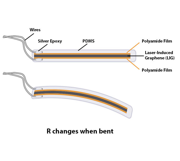
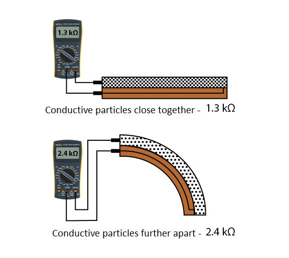
The sensing principle is straight forward and can be seen in the below diagrams I adopted from here As When the sensor is straight, the patterned LIG particles give a resistance of about 1.3k Ohms. When the sensor is bent, the LIG particles move further apart, increasing this resistance (to about 2.4k Ohms when the sensor is bent to about 90°)
Sensor Design and Fabrication
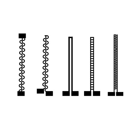
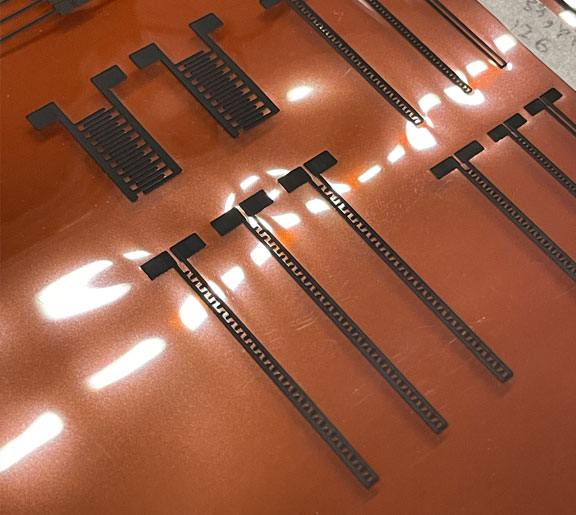
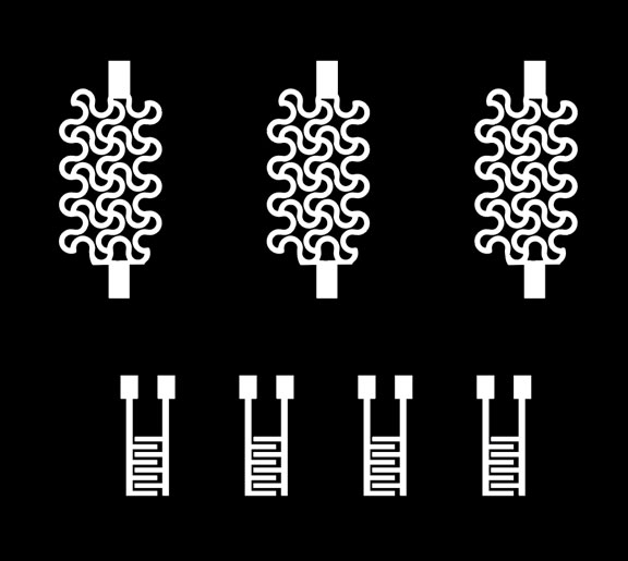
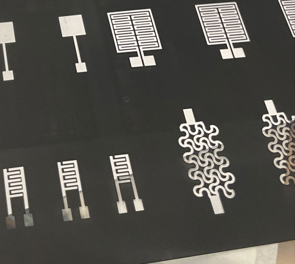
For the design, I wanted to experiment with many resistive arrangements, including straight lines , serpentine lines, shunts , and interdigitated designs, to see the effect on the performance. However, something catastrophic happened later, which left me with one functional sensor!
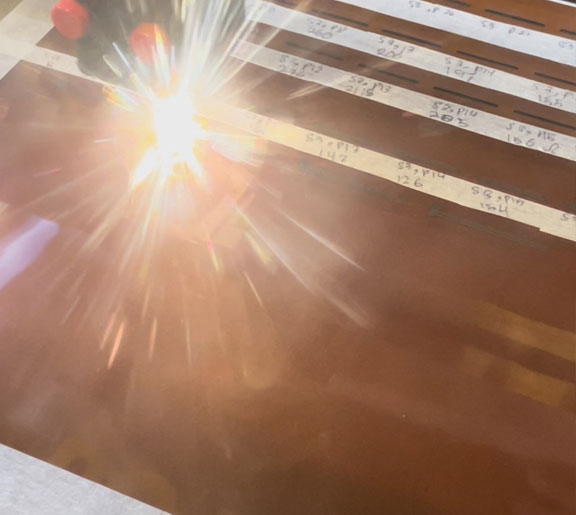
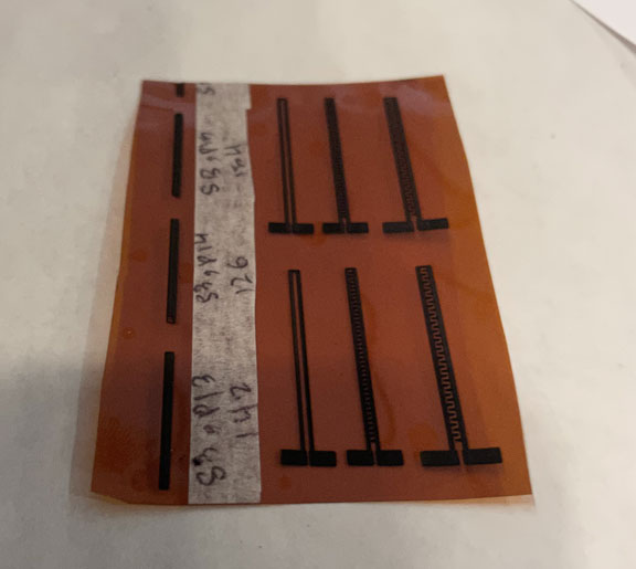
The fabrication process starts by irradiating a polyamide sheet with a CO2 laser using the optimized settings. Then, I cut the fabricated sensors into small parts and taped them to a dish to prepare for casting. Afterward, I tap copper tape with conductive adhesive to make the connection later on. Finally, I cast a thin layer of PDMS on the dish and leave it to cure in the oven at 60 degrees celsius for an hour
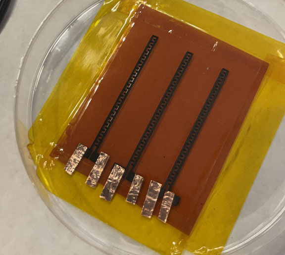
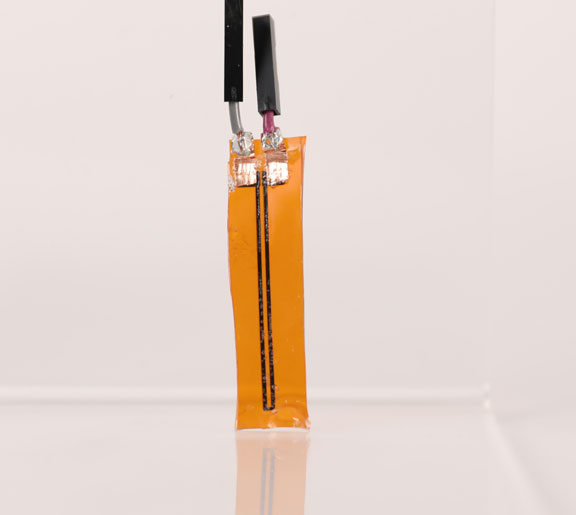
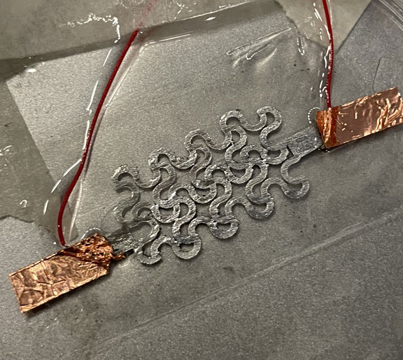
LIG Flex Sensor !
The photo on the right shows the final LIG Flex sensor wired and ready to be tested !
Board Design and Milling (Resistive)
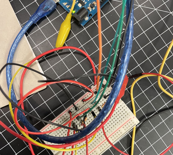
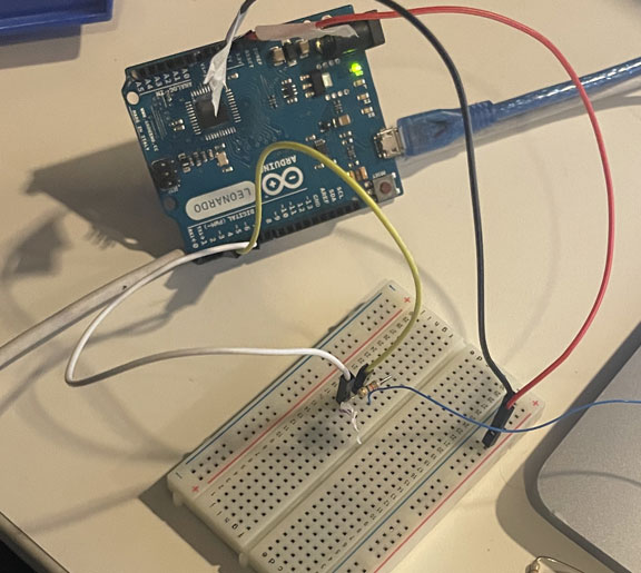
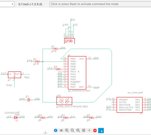
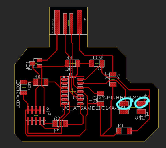
Before moving into Fusion 360 and PCB design, I tested the output of my fabricated sensor using an Arduino board and voltage divider circuit on a breadboard. After confirming that I could get detectable reads from the ADC, we started with the PCB design. We used the SAMD11 as our microcontroller and referenced Neil's example for the Wheatstone bridge circuit for the RTD sensor as an example. Two pads were defined as the pads for our sensor shown below.
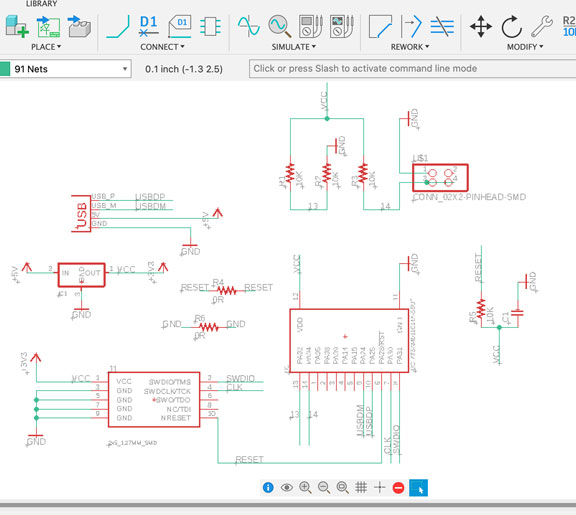
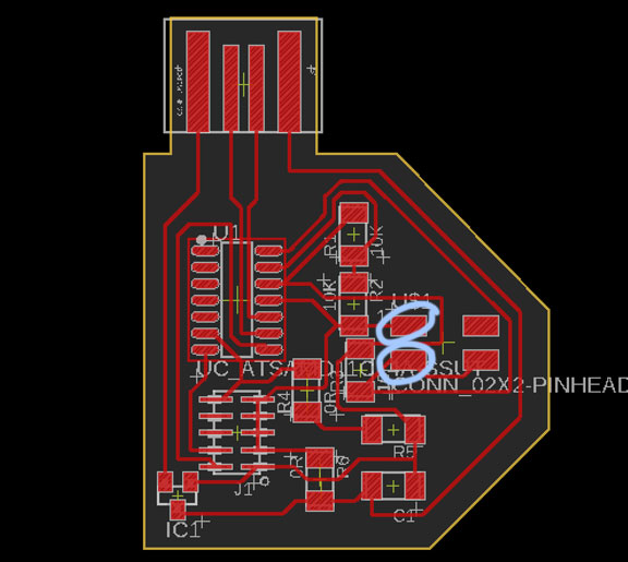
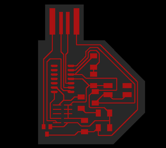
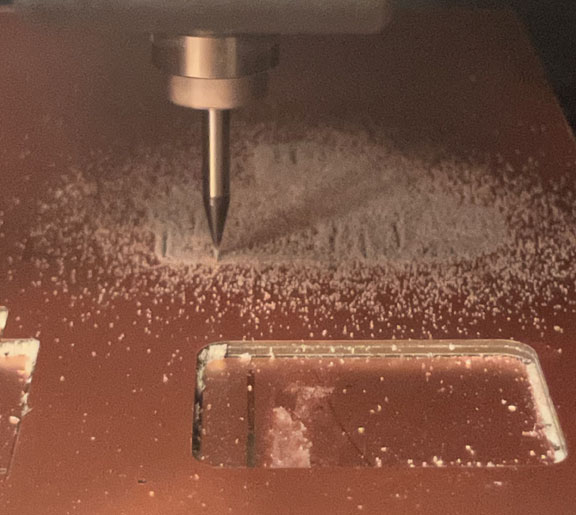
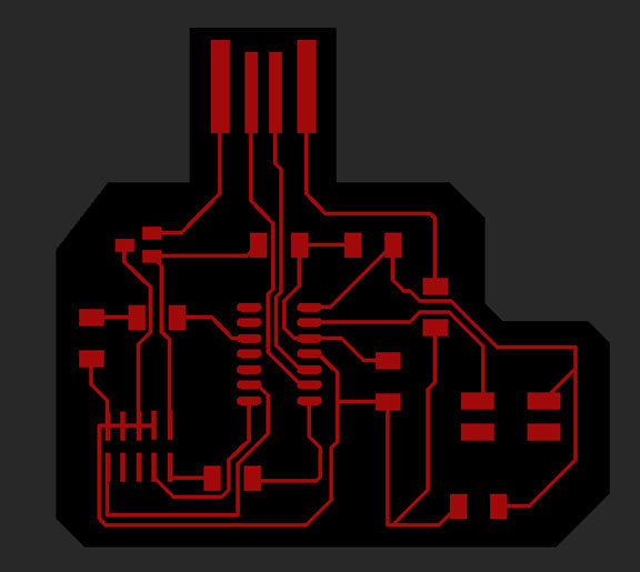
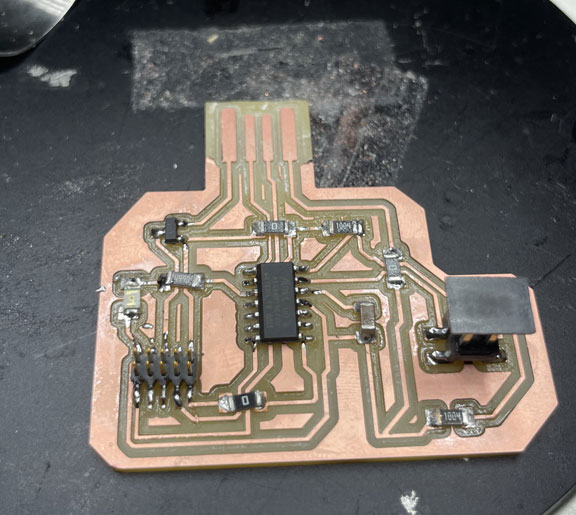
The final exported board into MODS is shown below, as well as photos of the milling and programming steps!
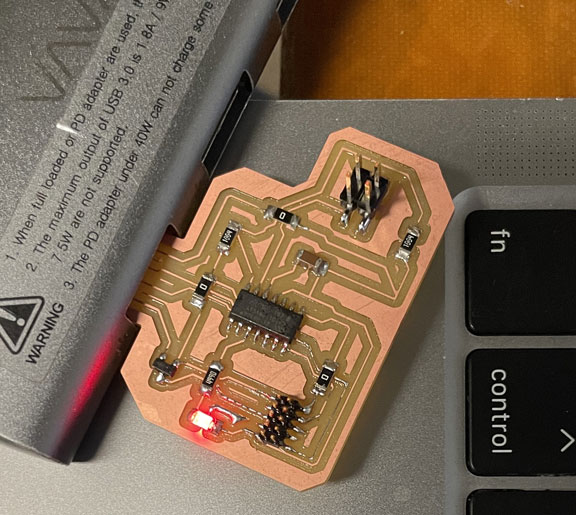
Final Board (Resistive)
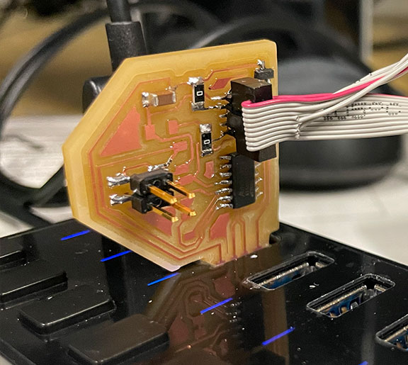
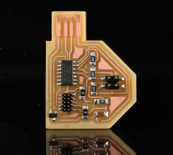
The photo on the right shows the final resistive-sensor PCB soldered and ready to read my LIG Flex sensor!
LIG Flex Sensor in Action
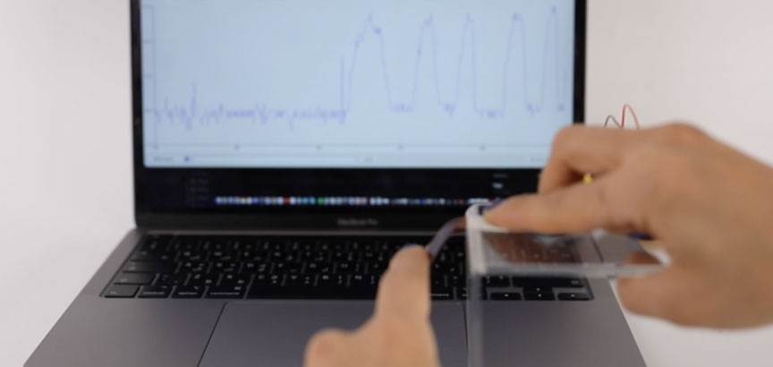
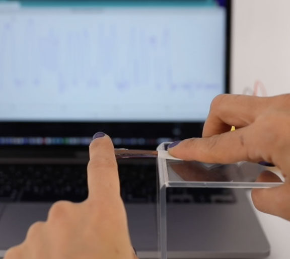
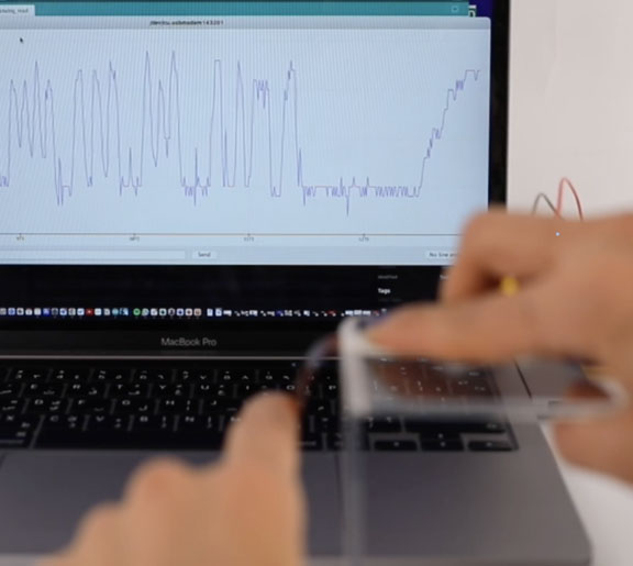
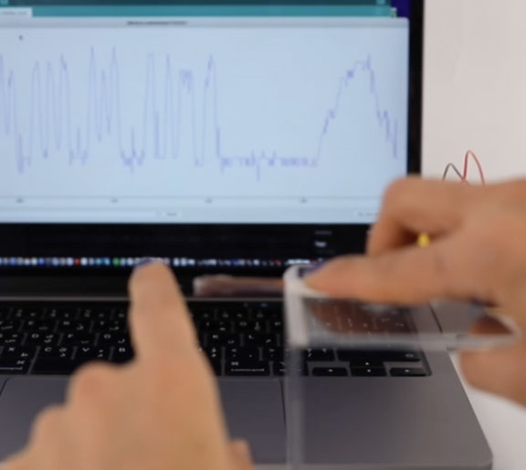
The video and photo below show the sensor's output in the serial plotter while being bent. The code was as simply using analogRead without any additional signal processing.
The photos below show basline singal of the sensor, and the spike while it is bent.
Flexible Touch Sensor - Liquid Metal (LM)
For the capacitive touch sensor, I decided to use liquid metal as the sensing material. My original idea was to leverage both the fluidity and conductivity of LM and pattern it on a stretchable substrate. However, the current version of the sensor is on a flexible substrate.
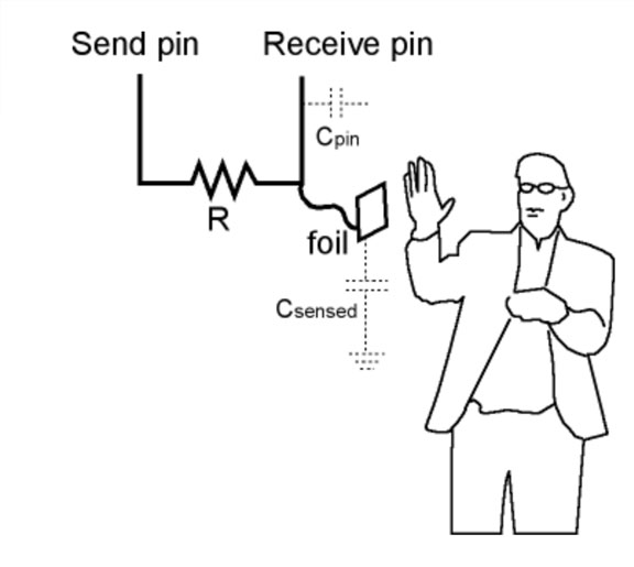
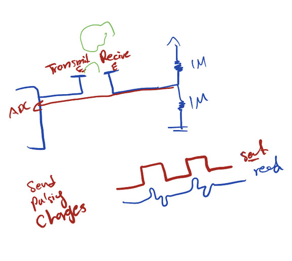
I used the step-response approach where I configured a pin as the transmit/send pin and another as the receive pin with my sensor attached with a large value resistor to the receive pin.
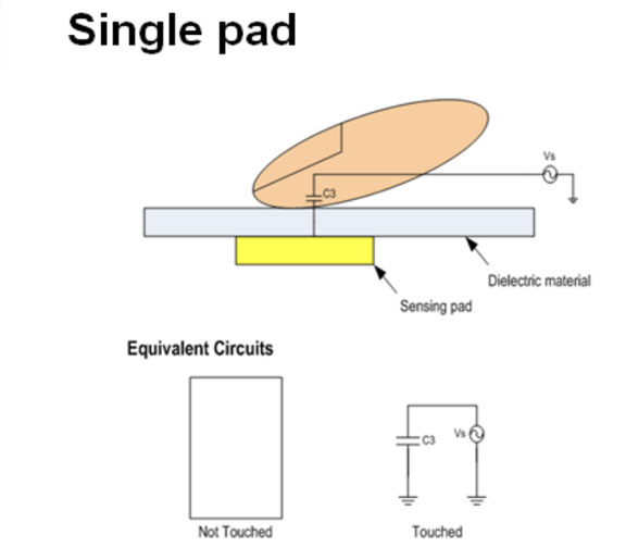
The sensor is composed of only one single capacitive plate and the human hand is utilized as the second plate coming with its own charge, disturbing the electric field and increasing the capacitance. Below I referenced some helpful diagrams and useful documentation to explain the concept and Neil's circuit from the class.
Sensor Design and Fabrication
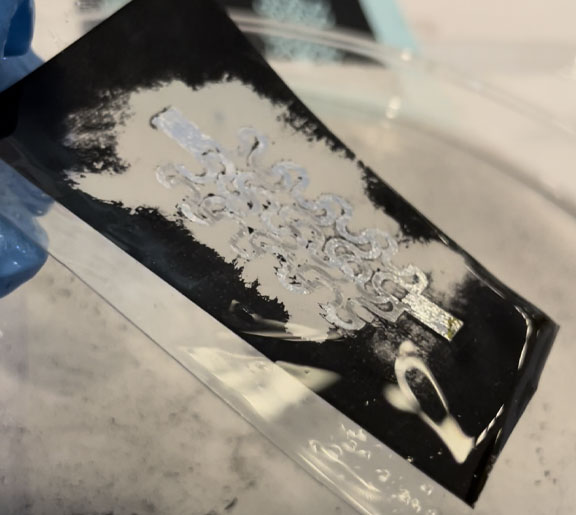
The fabrication process relies on a method I am currently developing and exploring .It utilizes an office laser printer and relies on the adhesion selectivity of the liquid metal to the paper/elastomeric substrate and not to the toner ink. First I print a mask of my sensor pattern into a flexible/stretchable substrate. The toner ink form the mask. Then I brush liquid metal everywhere.
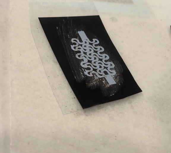
I later rinse the substrate with acetone to remove the toner (mask) after the acetone evaporates; I use copper tape for wiring and finally, I cast a layer of PDMS for mechanical stability and insulation.
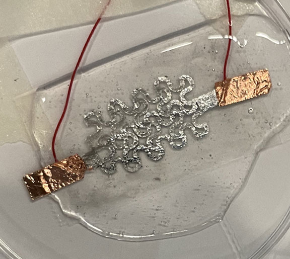
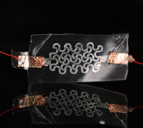
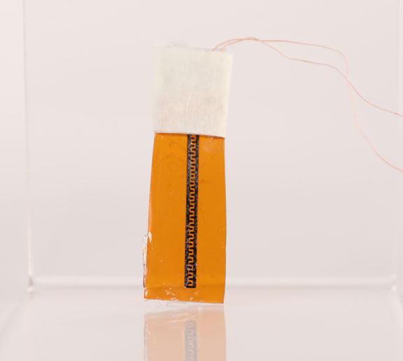
LM Touch Sensor !
The photo on the right shows the final LM Touch sensor wired and ready to be tested !
Board Design and Milling (Capacitive)
I also tested the output of my fabricated sensor using an Arduino board and a 1M resistor on a breadboard. After confirming that I could get detectable reads from the ADC, we started with the PCB design. We used the SAMD11 as our microcontroller and referenced Neil's example for step-response circuit with the copper pads as the sensing plate . Two pads were defined as the pads for our sensor shown below
The final exported board into MODS is shown below, as well as photos of the milling and programming steps!
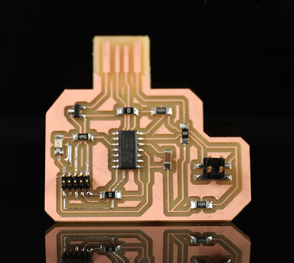
Final Board (Capacitive)
The photo on the right shows the final capacitive-sensor PCB soldered and ready to read my LM touch sensor!
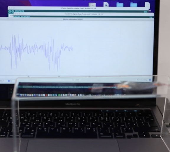
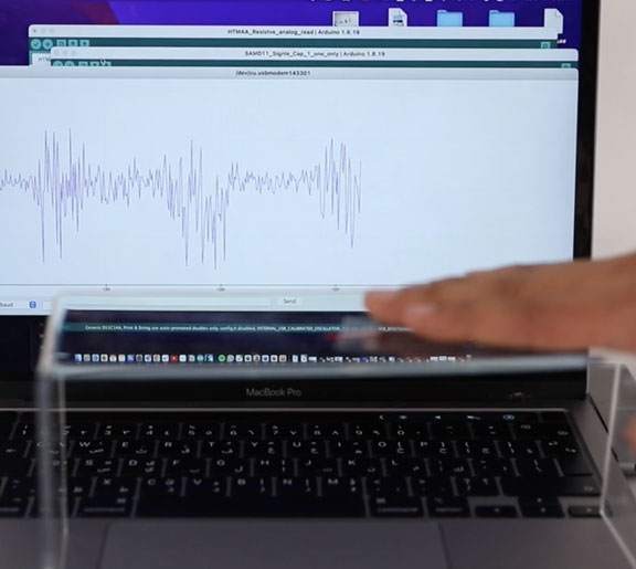
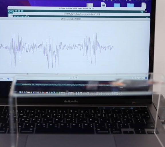
LM Touch Sensor in Action
The video and photo below show the sensor's output in the serial plotter while being bent. The output is simplay the raw output without additional signal processing. It an be improved
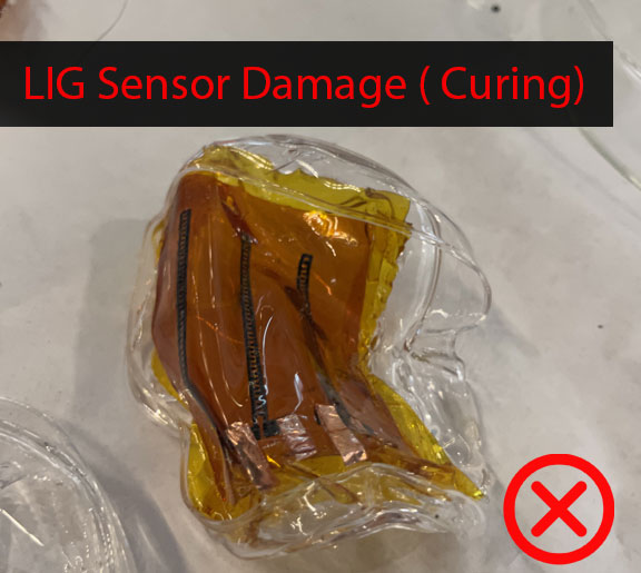
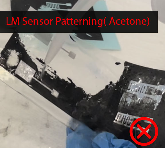
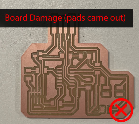
Issues & Failures
I experienced many issues and failures during the fabrication process of the sensors as well while connecting sensors to the boards.