Tools: Arduino IDE, Processing
Processing GUI
This week's assignment was to write an application that interfaces a user with an input &/or output device that we have made in the past weeks. I decided to use Processing , a versitle integrated development environment, to create a graphical interface with my laser induced grapehen (LIG) flex sensor that I created in week 8.
Given that my resistive sensor is essentially a potimeoneter, I came across this applicable tutorial that helped me get started with Processing language and environment.
The implementation consists of two parts: first, acquire the data from my SAMD21 board, which I already did in week 8. Second, communicate that stream of data via serial communication to processing software I picked a simple representation which is basically mapping the resistive sensor output to change the size of a circle.

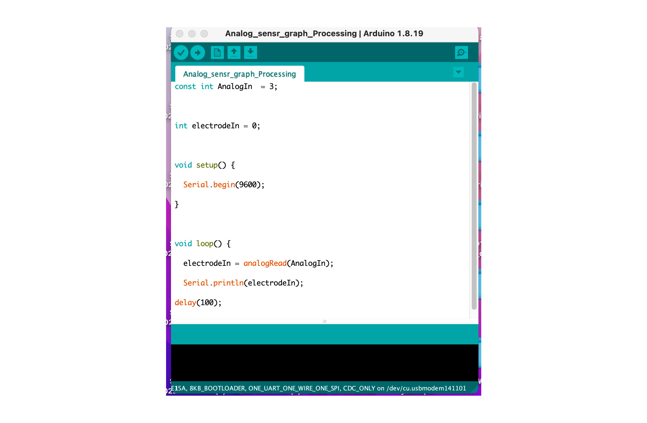
Arduino IDE !
The basic analog readout Arduino code is shown below.
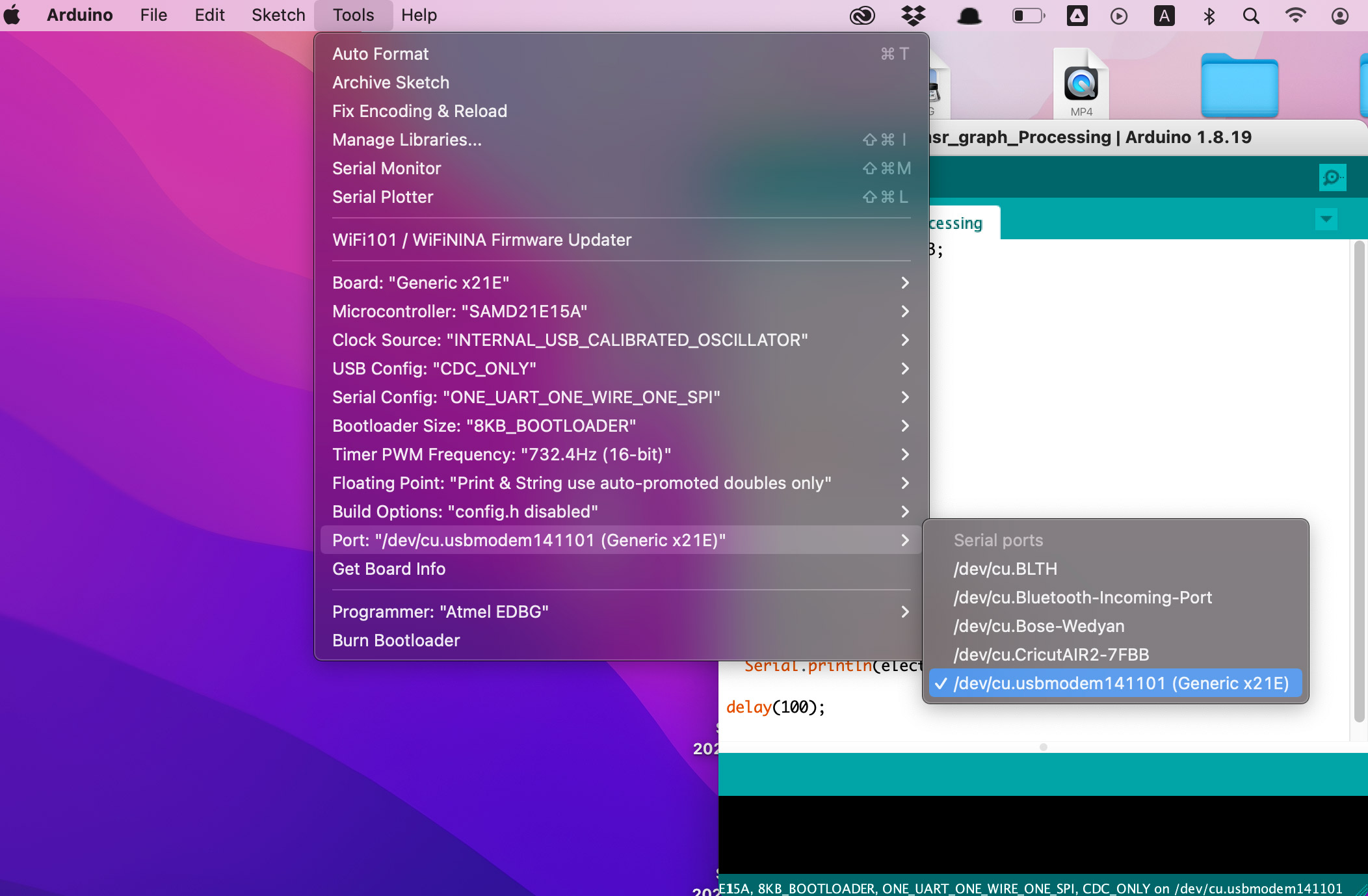
It is important to note down the exact port name your board is connected to, as you will need to input that later in Processing IDE
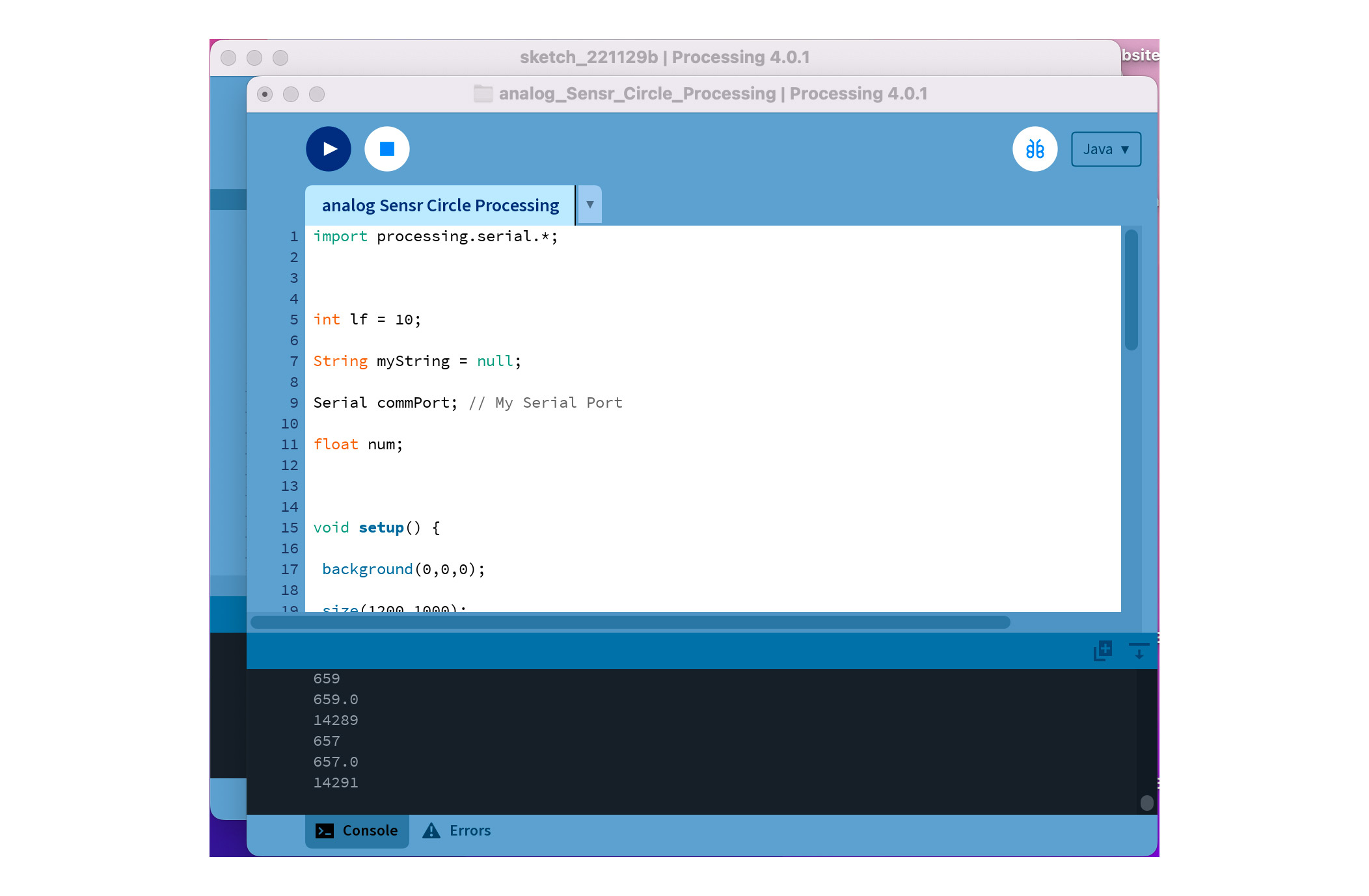
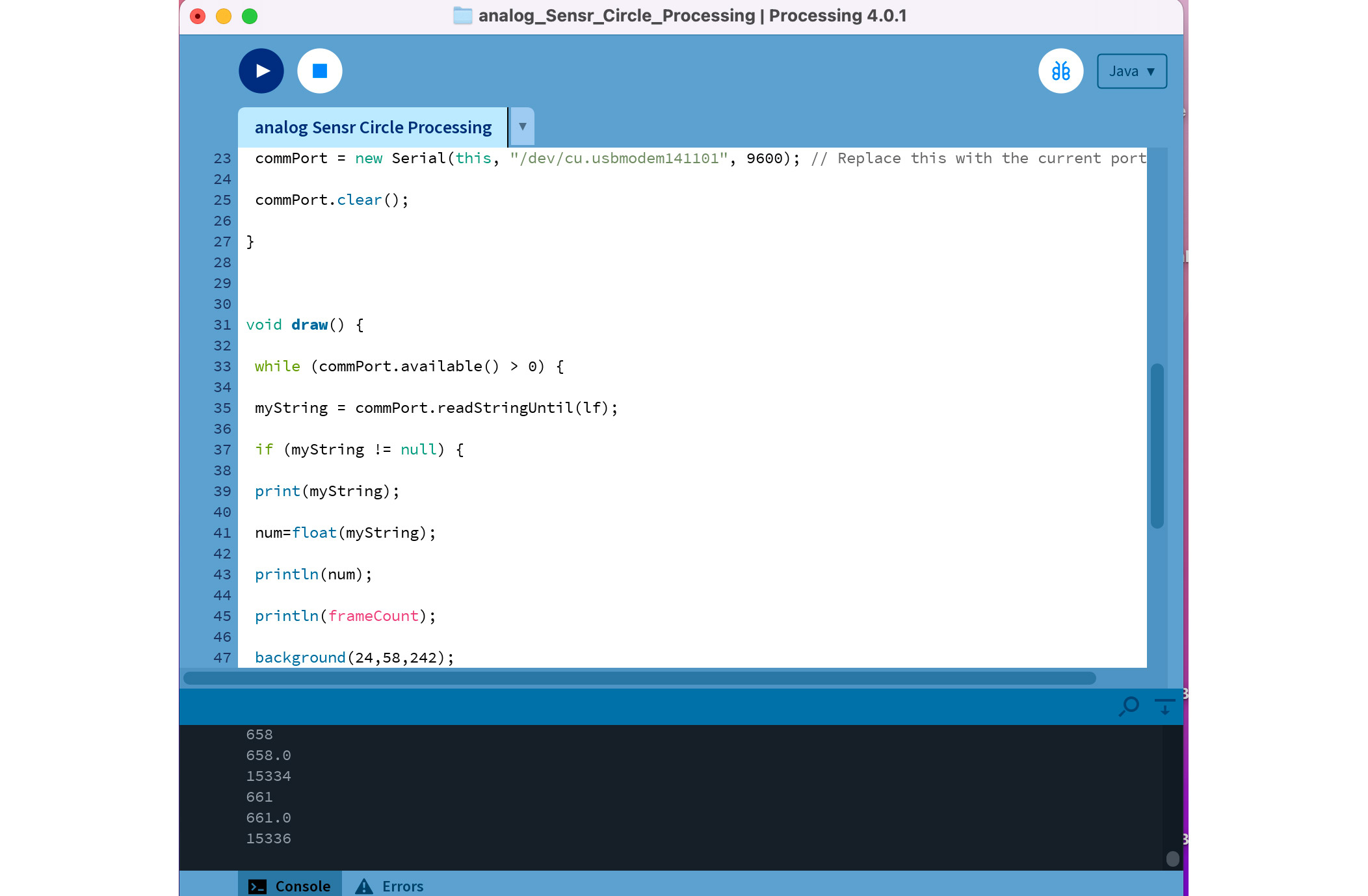
Processing
Processing code is below
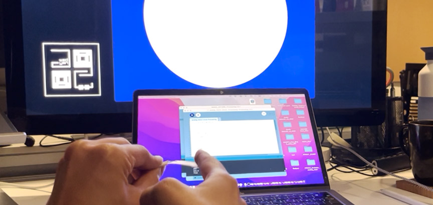
Processing GUI in Action!
The video below demonstrates the implementation described above. Since the stack of sensors consists of LIG grown on PI and a PDMS layer on top. You can see as the sensor is being bent in the right direction, the circle size increases as R is increasing as a result of LIG particles being stretched apart from each other. On the other hand, as the flex sensor is being bent in the left direction, LIG particles get closer to each other a little bit, which decreases the resistance and the circle size accordingly.