Tools: Fusion 360, MODS, EDGB, PCB Milling (SRM-20), Soldering, Arduino IDE
Output Week
This week is all about output devices. As opposed to last week, where we were trying to sense something in the world around us, we are trying to convert information into a human-perceptible form this week!
Building on my last week's assignment, I decided to add an RGB LED that can be controlled using my fabricated laser-induced graphene (LIF) flex bend sensor from the previous week. Additionally, I re-designed a newer version of my microcontroller board, which is now based on the SAMD21 and more minimalistic than my older designs.
LIG Flex Sensor !
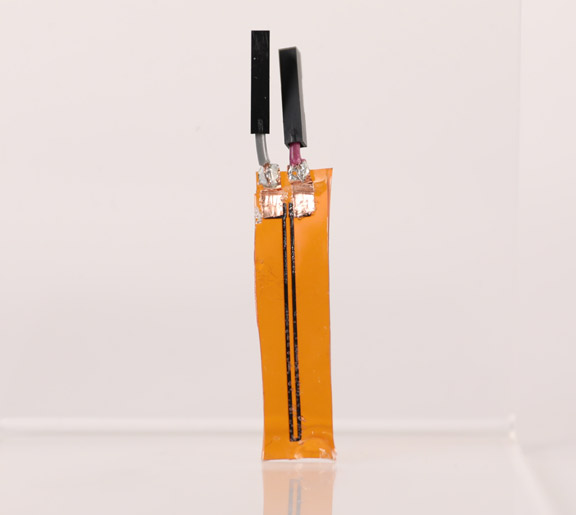
The photo on the right shows my flex LIG sensor from last week wired and ready to be connected to an output device for control purposes !
Board Design and Milling (Resistive)
One of my main goals this week was to improve my board routing skills and minimize the number of components I use in my board as much as possible. My first board, which I designed in week 4 was giant and had six 0 Ohm resistors, indicating poor routing. This was also confirmed by Neil's comment;" your routing is horrible!" which it definitely was. I should not need to use that many jumper resistors, given that my board had only a resistor and an LED.
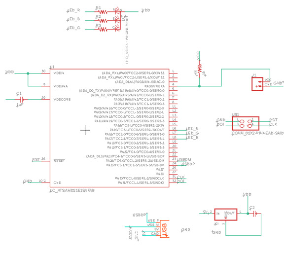
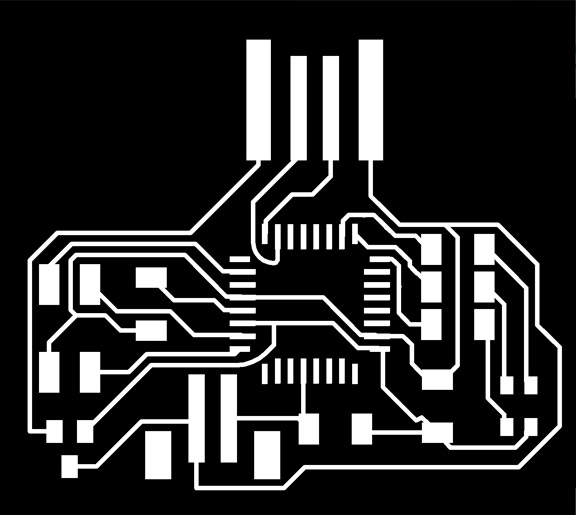
One helpful routing trick I found that can improve routing and make it less time-consuming is to look at good boards designed by other people who used the same microcontroller and similar peripherals. Here, I used Quentin's piano board as a reference example since he used the SAMD21 and tried to make it as minimal as possible. As you can see in the schematic below, the board has the minimum to get the SAMD21E functioning. The pull-up resistor and decoupling capacitor on the RESET pin were added as advised in the datasheet. I created a voltage divider circuit that is connected to two pads for my resistive sensor (highlighted in green). Finally, I added an RGB LED as my output feedback device and connected it to 3 PWM-capable pins. I also used the 4-pin connector here instead of the 6-pins header, which also helped in making routing more minimal.
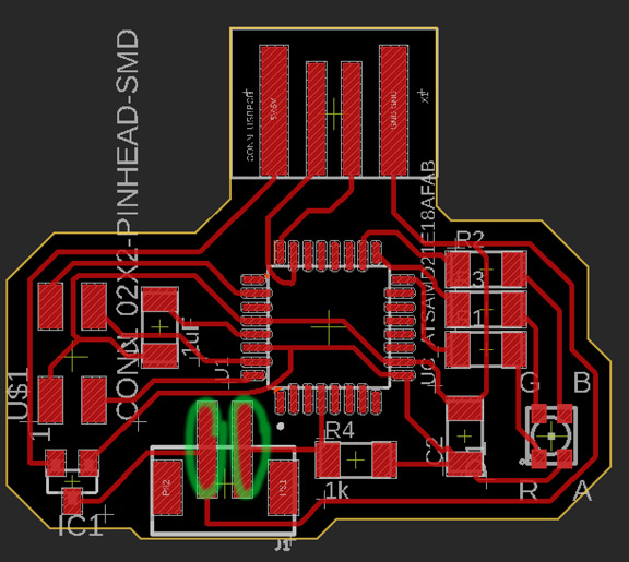
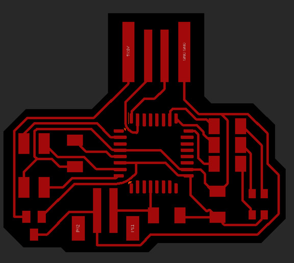
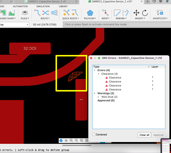
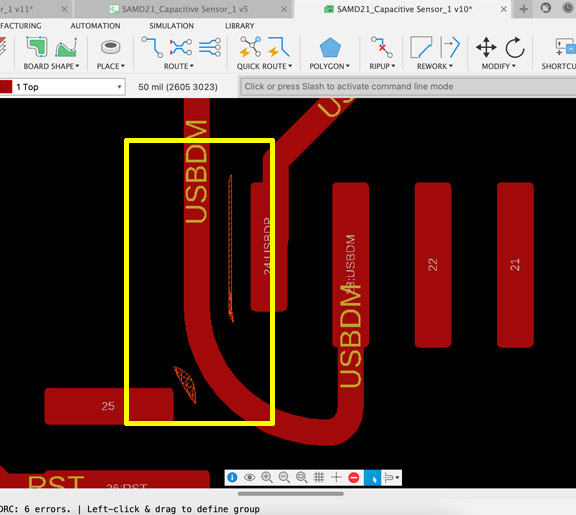
Since I was determined to make the board as small as possible, Fusion 360 was a little bit upset and gave me some clearance errors near the traces I routed out of the microcontroller using the rout bend tool as you can see highlighted in yellow. I had a feeling it would be resolved during milling and decided to give it a shot so I exported it to MODS as is. I was pleased with the final desing, especially since I did not need to use any 0-ohm resistor!! From 6 to none, that is progress to me :)!!
Final Board
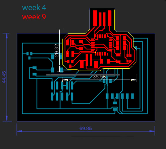
The image on the right shows a nice comparison between the size of my week 4 board compared to this week's board when superimposed on top of each other
Board Milling and Soldering
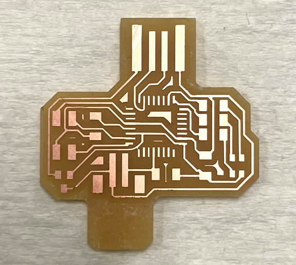
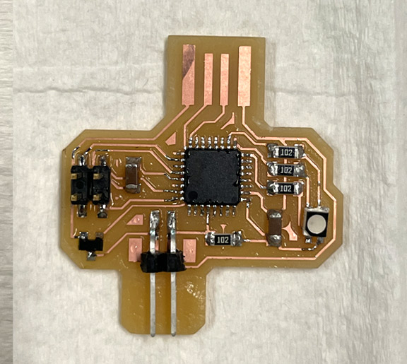
Milling using the Roland SRM-20 the board went very well, even the parts I got warned about as they were too close to each other! I decided to elongate the bottom part of the board next to my sensor pads to give space and support for my sensor to set on. Soldering went well too, I used a lot of flux during the process which was helpful.
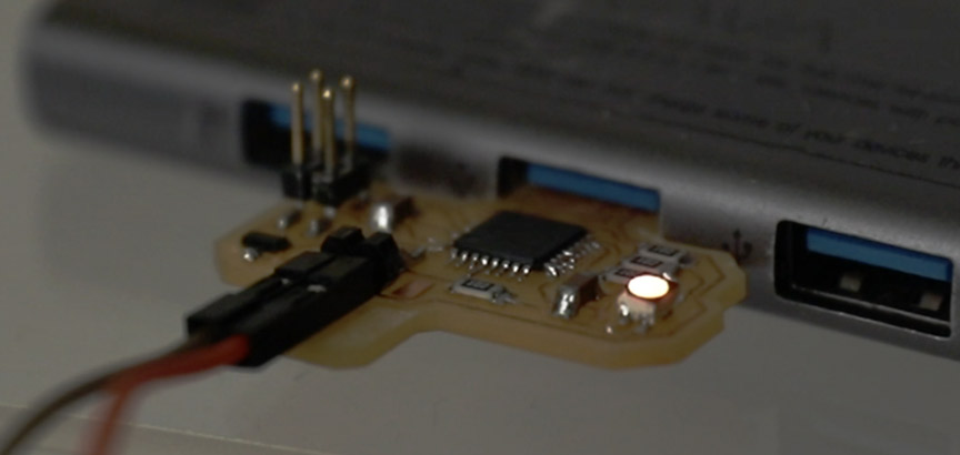
After successfully loading the ATSAMD21 Arduino bootloader using EDBG , I used a simple code where the RBB LED would sequentially change color as an initial test, as seen in the video below.
Final Board (Input + Output)
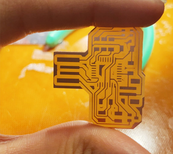
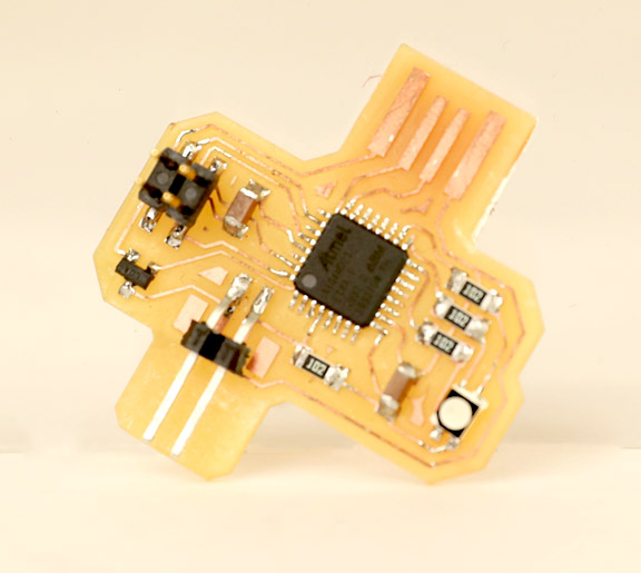
The photo on the right shows the final fabricated board that has resistive-sensor readout + for the LIG Flex sensor and RGB LED as an output
LIG Flex Sensor & LED Control
In order to control the intensity of the LED with my flex resistive sensor, I flashed a new code where I first read the analog output from the sensor and then map that value to the brightness of the LED, as shown in the video below.
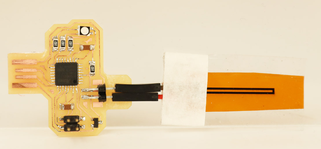
The photo below shows the final board connected to the LIG flex sensor.
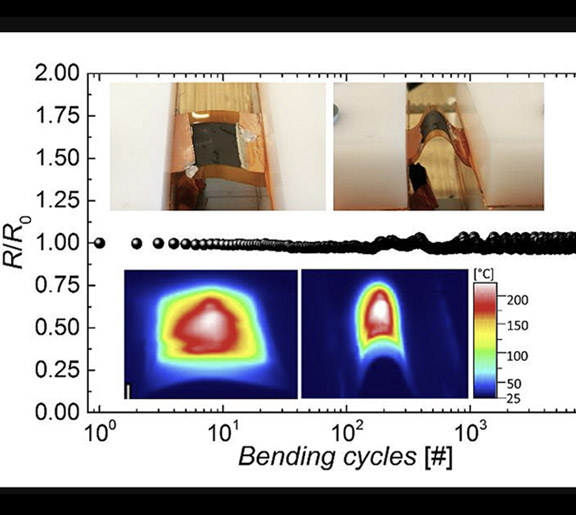
Fabricating heaters out of laser-induced graphene has recently emerged due to LIG unique properties, such as high porosity, excellent electrical conductivity, good mechanical flexibility, high working range (>600 °C), and high-temperature efficiency. Thus, I wanted to try to make some heaters using the same process I have been doing for the sensor, which is irradiating polyamide sheet with the GCC laser.
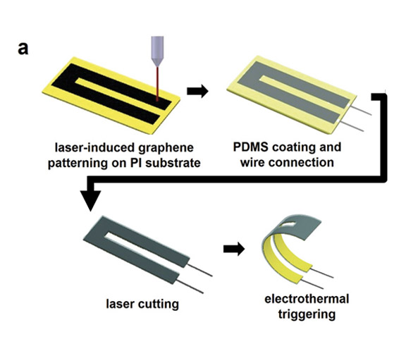
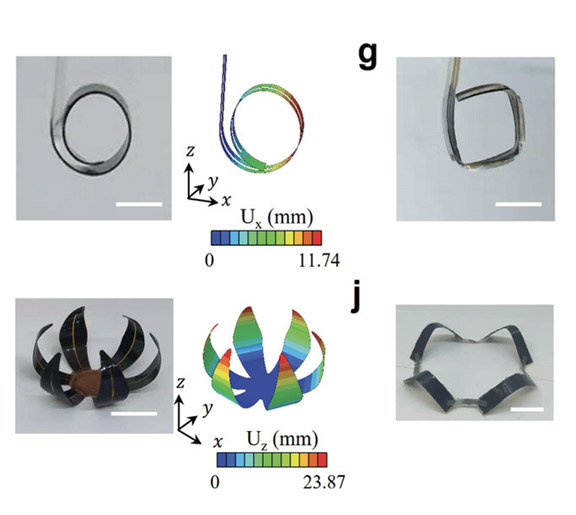
What is even cooler is utilized these heaters to create soft mechanical actuators that are electrothermally controlled. This can happen by coating the PI/LIG heater with a thin layer of polydimethylsiloxane (PDMS) so that the actuator now consists of the PI, LIG, and PDMS trilayer. LIG will act as the heater, and the thermal expansion difference between PI and PDMS upon triggering the heater can deform the structure to bend or do other 3D architectures via strategically designed global folding and/or local bending movemnets.
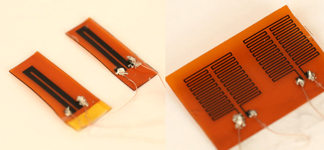
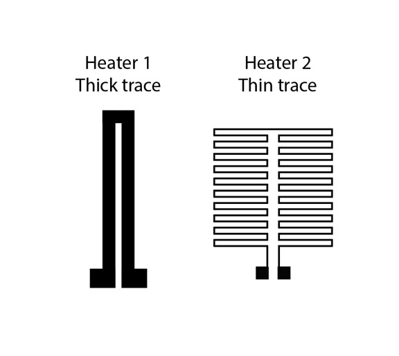
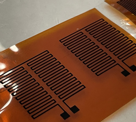
For the design, I wanted to experiment with two heater designs, one would yield a high resistance and the other is quite thick in order to lower the resistance. For the fabrication,I following the process I used last week
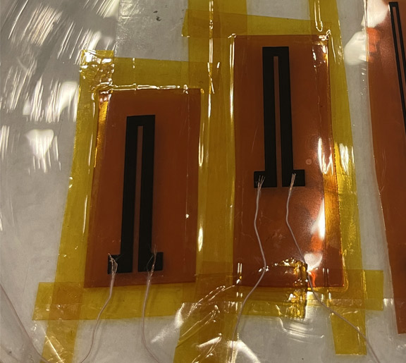
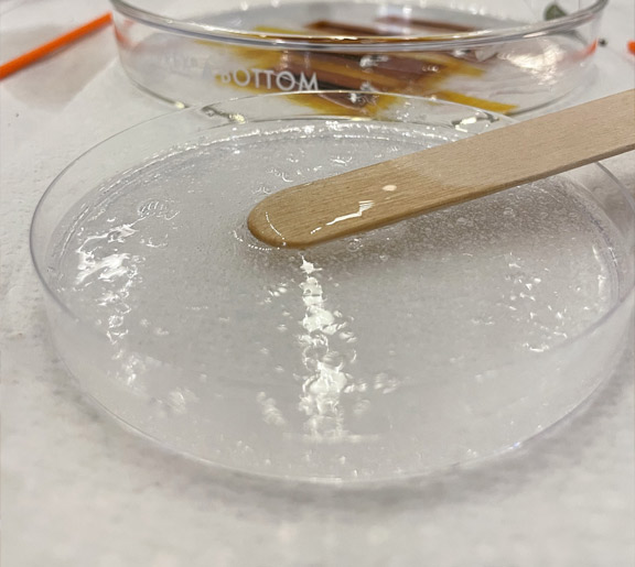
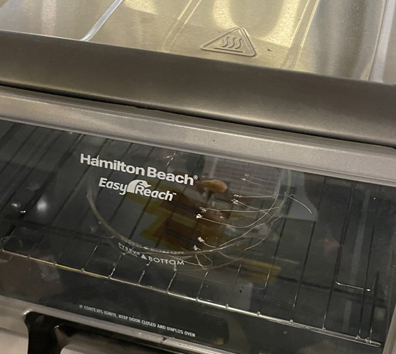
The fabrication process starts by irradiating a polyamide sheet with a CO2 laser using the optimized settings. Then, I cut the fabricated sensors into small parts and taped them to a dish to prepare for casting. Afterward, I tap copper tape with conductive adhesive to make the connection later on. Finally, I cast a thin layer of PDMS on the dish and leave it to cure in the oven at 60 degrees celsius for an hour
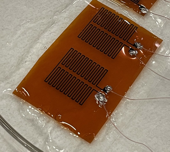
The photo below shows the final fabricated LIG heaters after wiring them using silver epoxy
LIG Heaters
Heater Design and Fabrication
High-Performance Graphene Heaters ?