Electric ATV
- Date: September 6th 2022 - December 22nd 2022
Final Project: Electric ATV
For our Final Project Raiphy and I will design, build, and manufacture an Electric ATV. Raiphy is mainly in charge of the Power Electronics in our vehicle given his background in Electrical Engineering, and I am responsible for the Mechanical aspects of the vehicle. I will also be responsible for small dashboard electronics such as a speaker system.
The Design
Background
This project started as an idea Me and Raiphy had over the summer. After a pretty tough Junior Spring, I wanted to do something big. All of my friends said it couldn't be done they called us crazy, even Anthony had his doubts. I wanted to leave it all out on the field, showing not only myself but people in general what can be accomplished with a little grit and technical knowledge. With that in mind I present Oliya: an Electric ATV project, the greatest senior fall project MIT has ever seen.
Overview
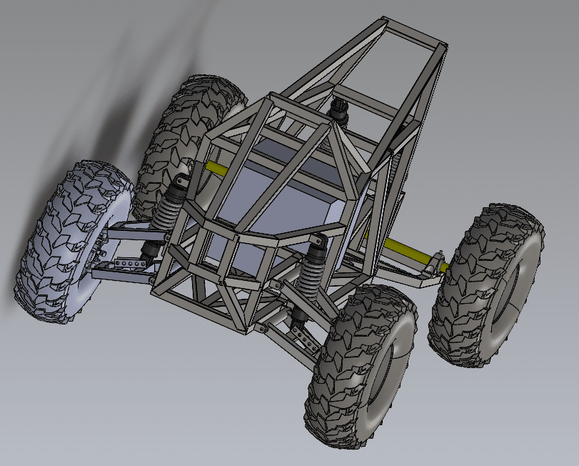
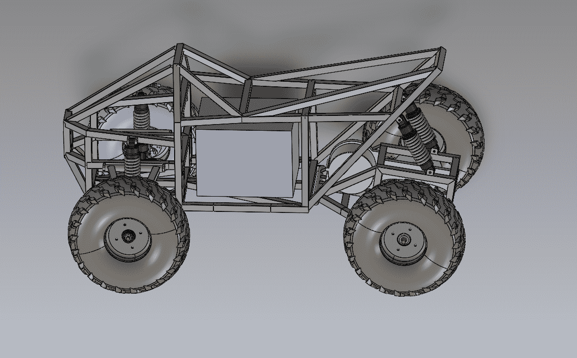
All of my friends make their own electric vehicles. Some make skateboards, some make bikes, but none have gone as far as making an off-roading, fully fledged, four wheeled vehicle with suspension. That is what I aim to do. Oliya will be a fully working electric ATV. Modeled after the Tesla cyberquad, Oliya features a steal frame made with recycled box tubing. Equipped with a 10 KW 3-phase brushless motor, Oliya will have the equivalent of a 200cc engine, making it a powerful contender against modern gas powered ATVs. Oliya will have 4 shock absorbers (rated for 2250+ ibs), giving even the heaviest rider a smooth ride. It will have two independent front suspension arms and one rear suspension arms. The total weight of the vehicle will be roughly 250 ibs making it ideal for speed and power applications.
Oliya is composed of 4 main assemblies: the vehicle frame, front suspension, rear suspension, and steering mechanism. The vehicle frame is made out of steal box tubing from recycled desks it is designed to support up two riders, and sustain forces from difficult terrain. The front suspension is modeled after double wishbone suspension, it has an upper and lower arm attached to the front wheel hubs. The front shock absorber is connected to the lower arm, similar to wishbone suspension. However, Oliya's front suspension is specifically designed for manufacturing. The rear suspension assembly will also include Oliya's power train. The motor and chain assembly will be connected to the rear axle all under the rear suspension assembly, which will be supported by two shock absorbers. Finally, the steering will be modeled after bike steering, featuring motorcycle handle bars and connected to the front wheel hub through ball and socket joints. The handle bars give a user extra torque for turning, removing the need of power steering.
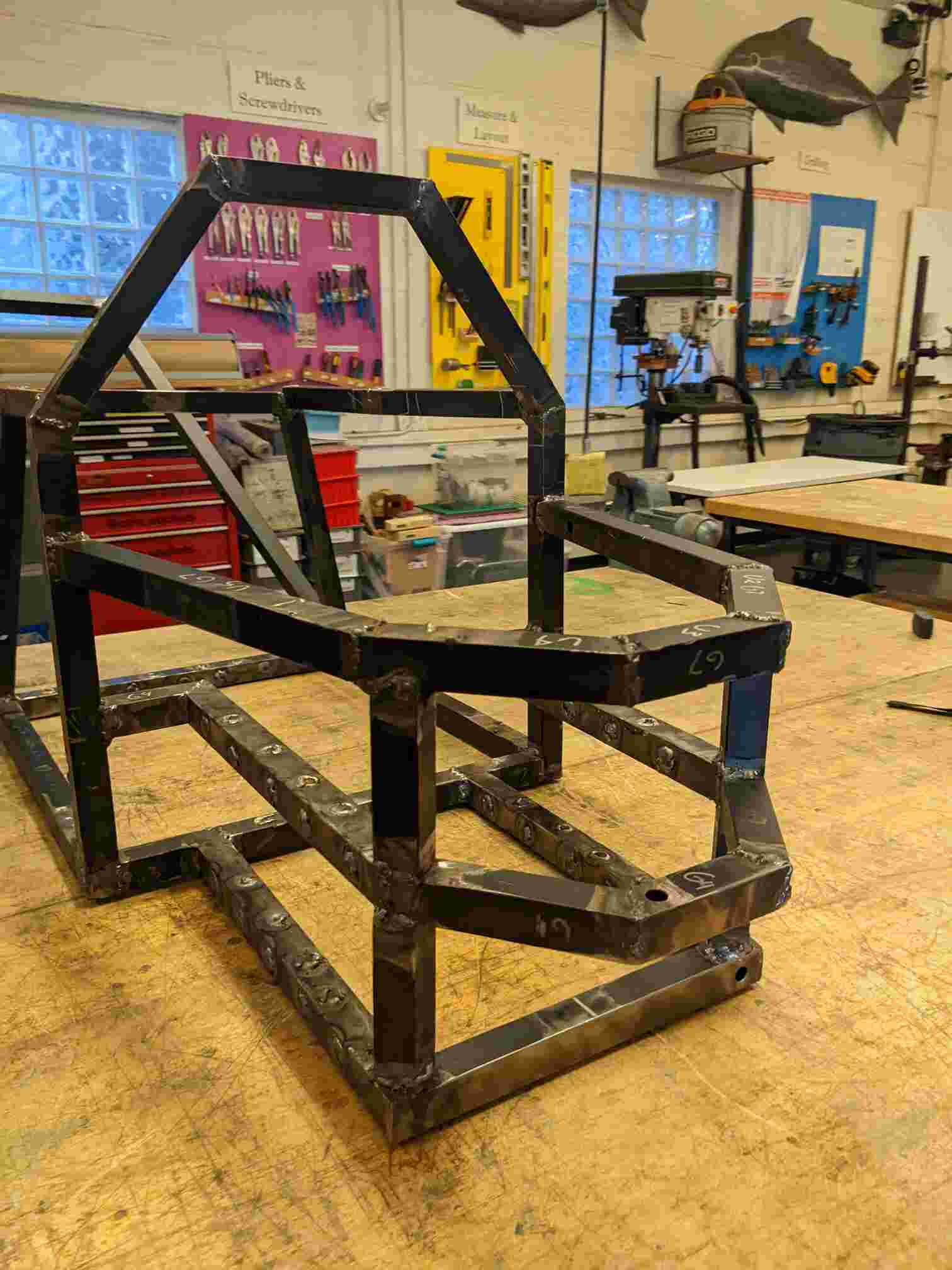
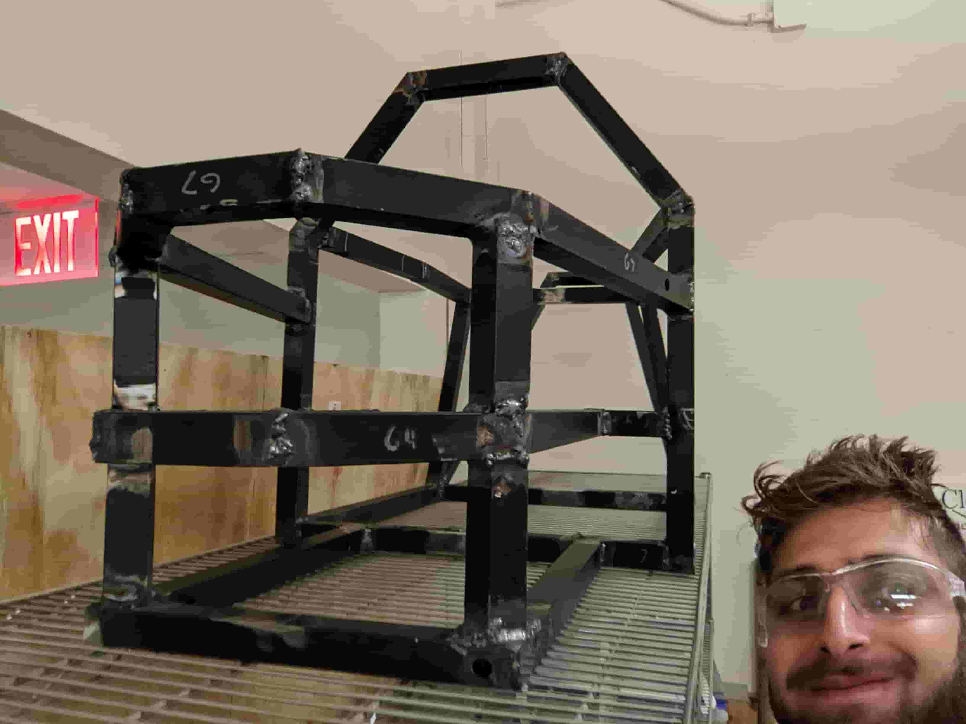
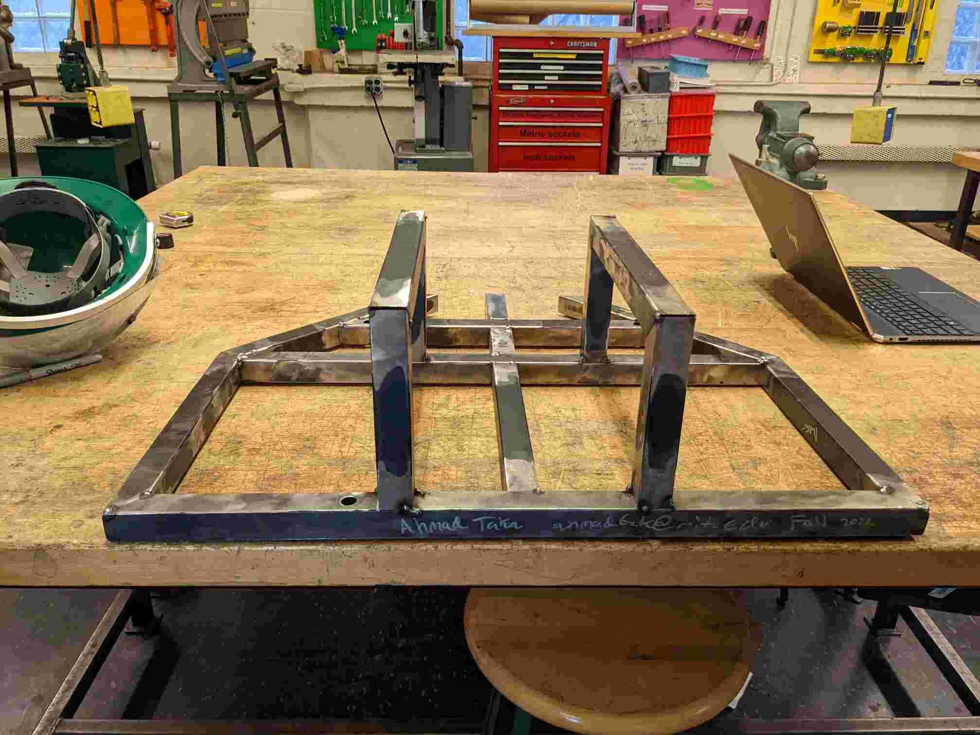
The Frame
This frame was sorta loosly modeled after the Tesla Cyberquad . I Designed it with high impact forces on the front and rear shock absorbers in mind. So lots of triangles in those areas. I also wanted it to be safe for me and Raiphy since neither of us had ridden an ATV before so I designed it with a lot of strength in the front. Lastly, I also took into account the size of the battery which is why we have a large open area in the middle where the battery is going to go. Since I am not a Mechanical Engineer and have never really done any heavy machinery or a CAD of this magnitude, I over-engineered this frame. This is just meant to be a prototype and just show people that just with a computer and some hard work, you can build anything.

The Front Suspension Assembly
For the front suspension, I modeled it after double wishbone suspension. Double wishbone is good cause it is easy to make compared to other suspensions and provides good stability. It is also really easy to mount to a vehicle frame it just requires to 3 mounting points all a fixed distance a part. It is also easy to work out the loads that different parts will be subjected to which allows more optimized lightweight parts to be designed. Which makes it perfect for our vehicle since we are using thinner steel tubing.
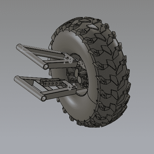
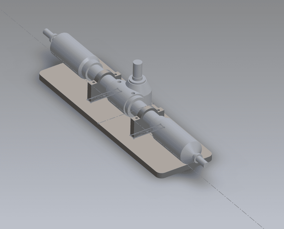
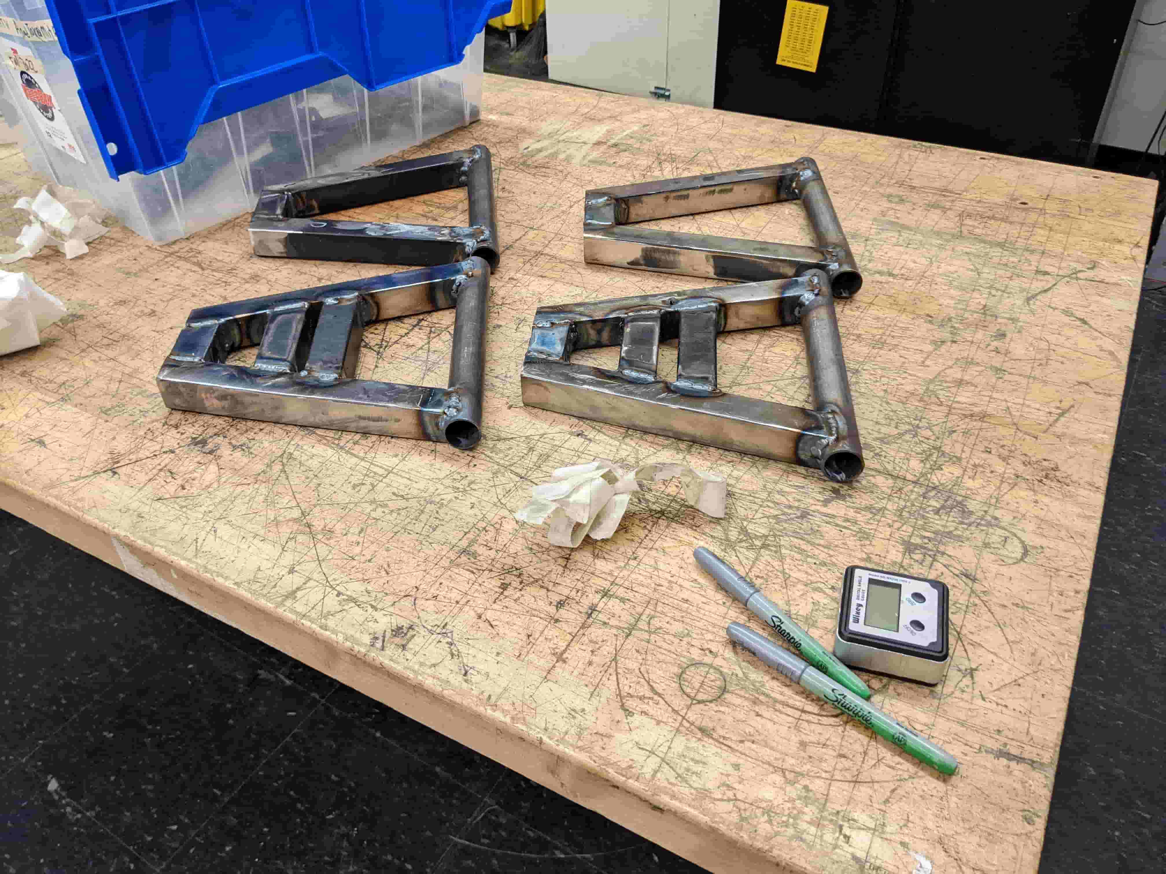
The Rear Suspension Assembly
For the rear suspension, I had to take quite a few things into account. First the electric powertrain; since the frame was going to have the battery and seat, and since the rear axle would move with respect to the frame, I decided to put the powertrain onto the rear suspension arm. This comes at the cost of making the rear suspension more complicated. However, it also makes the powertrain less complicated as I wouldn't require a two stage reduction to get to drive the rear axle. Its also worth noting that the placement of the motor was designed close to the pivot of the rear suspension. This is to limit the rotational inertia of the rear suspension, which in turn would reduce its torque on the mount and force on the rear shocks. In anycase, I designed the rear suspension to be easy to weld (for the most part) and easy to manufacture, having only trivial planar to cut. With all this in mind I came up with a very decent CAD for the Rear Suspension, with the exception of the Motor Mount Plate, designed and machined by Raiphy.
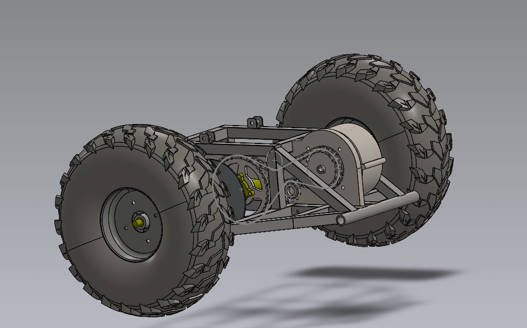
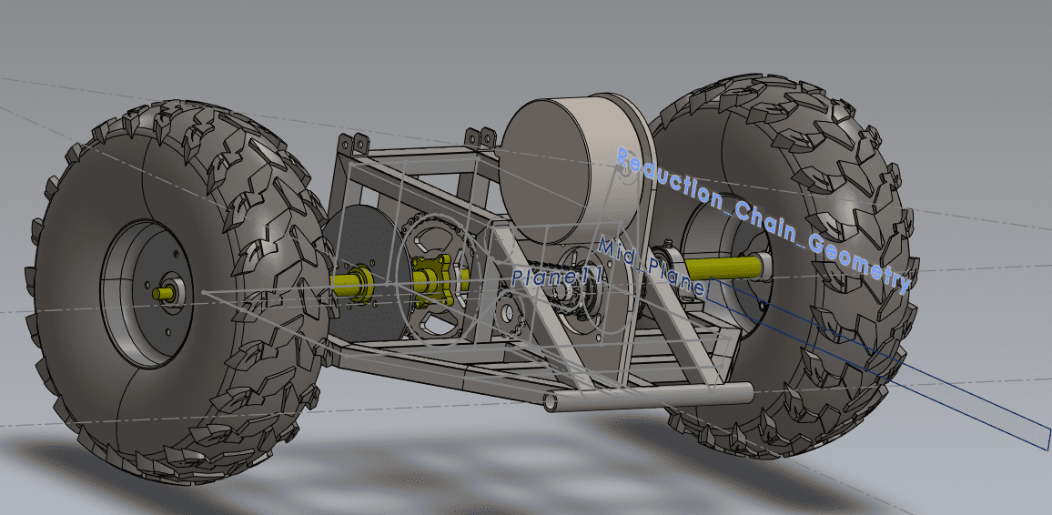
After redesigning the Rear Suspension Assembly (See weeks 12/14 and 12/19 in implementation below for more details), the new Rear Suspension adds another gear reduction. This new design increases our torque and lowers our top speed. This is exactly what we want because we are limited in Max RPM of the motor by the motor controller. Before our gear ratio was 9T to 37T which means we have ~4 times as much torque that the motor can output. However with the new ratio we have 9T to 24T then a 10T to 37T, resulting in a total 1:7.45 gear ratio. This is enough for a top speed of 15 mph given our motor and controller and enough torque for our purposes.
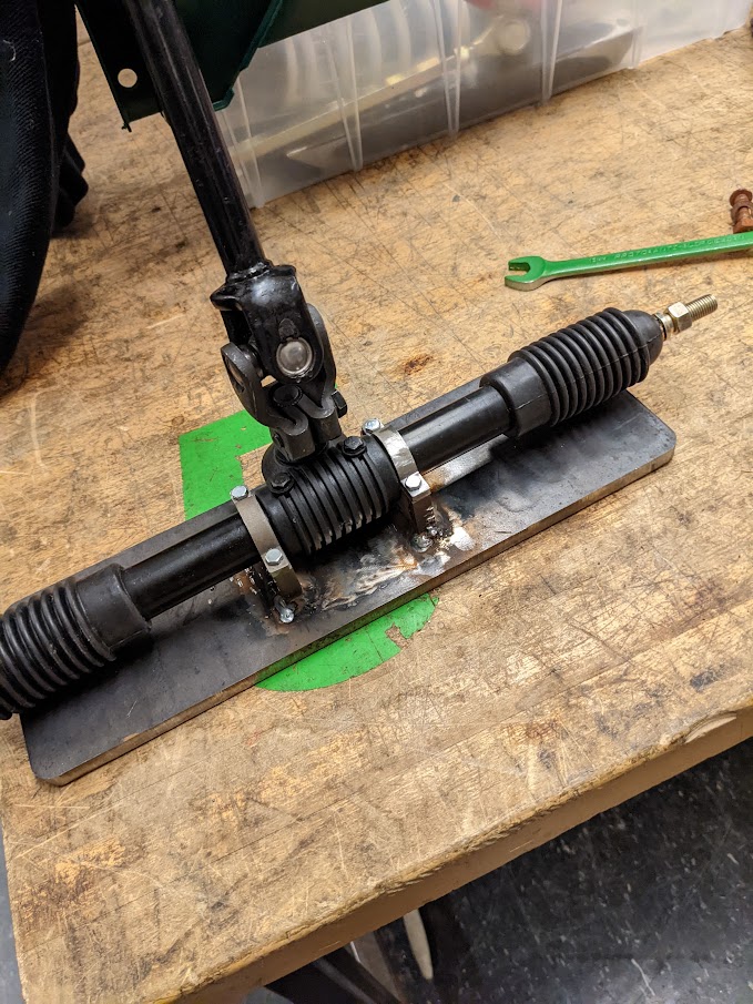
The Steering Assembly
For the steering,I found go-kart tie rod steering on amazon ( here) which I decided to buy and CAD around. This steering assembly will give us Akkerman-steering geometry, which is basically where the wheel turns according to its turning radius. So the left wheel turns more left during a left turn and the right wheel turns more right during a right turn.
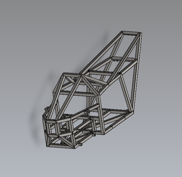
Disclaimer on CAD
Due to the scale of this project many things had to be improvised and designed flexibly. As you will see with many things in our implementation did not match to the CAD. The CAD here serves as more of a guideline than a rule and is simply meant to give our implantation some structure to follow. That being said many elements of our frame and suspension assemblies match the cads almost exactly.
Implementation
Weekly Work
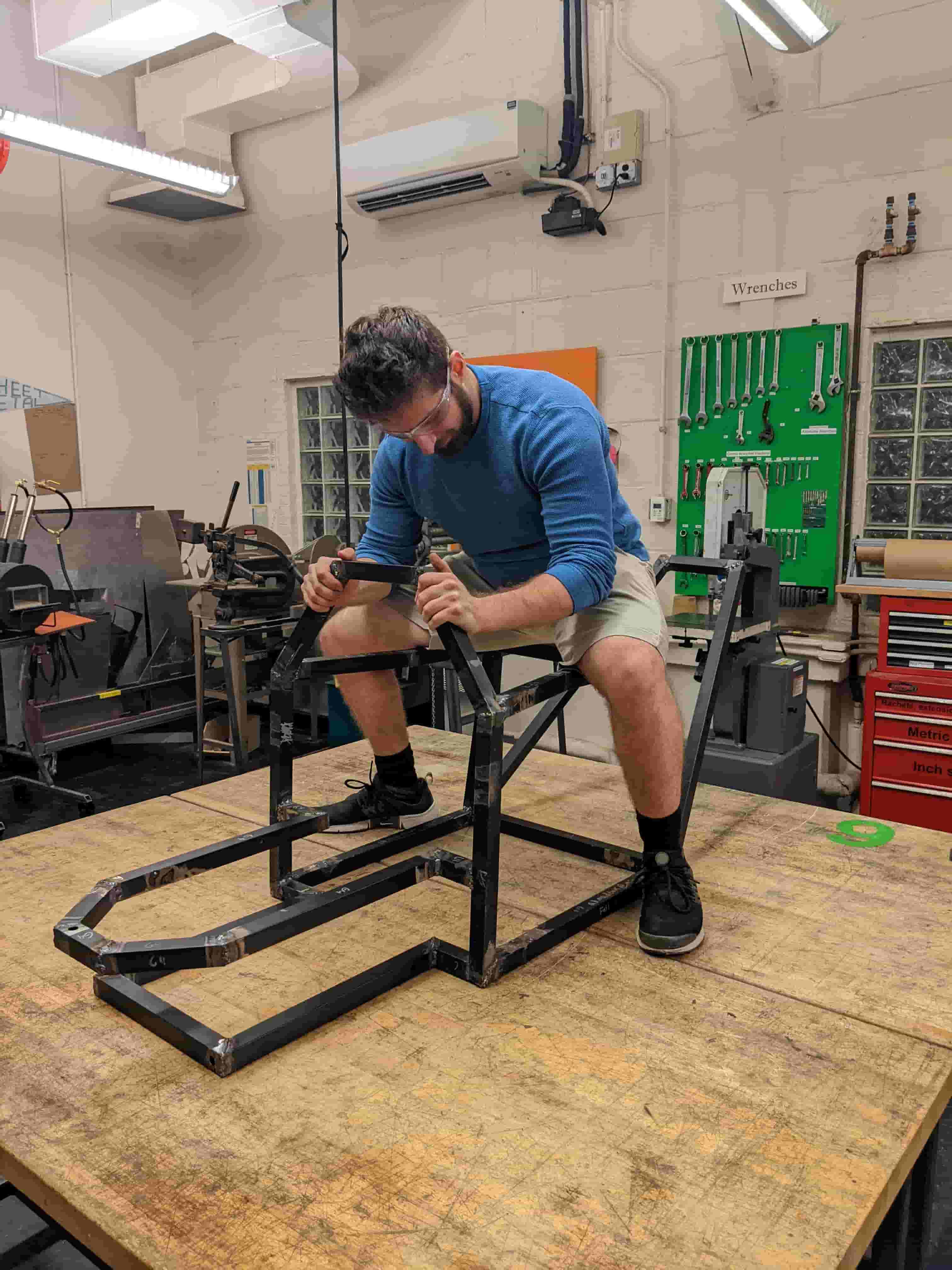
Its very hard for me to convey the level of work we did in sum. Me and Raiphy easily put in 30+ hours each week (some weeks 80-90 hours), in addition to maintaining our schedules for class and completing our other weekly assignments. Each week was a new challenge not only mentally but also physically, towards the end it took almost my entire being to muster up the energy and strength to finish. For each week I took progress photos (shown below). The best way I thought to convey what we did each week was with a timeline and small description. Also to better focus the multiple parts of this project, I will highlight some of the designs I made for this project that I think exemplify each technique I learned in class.
-
Week 1: Starting On Frame
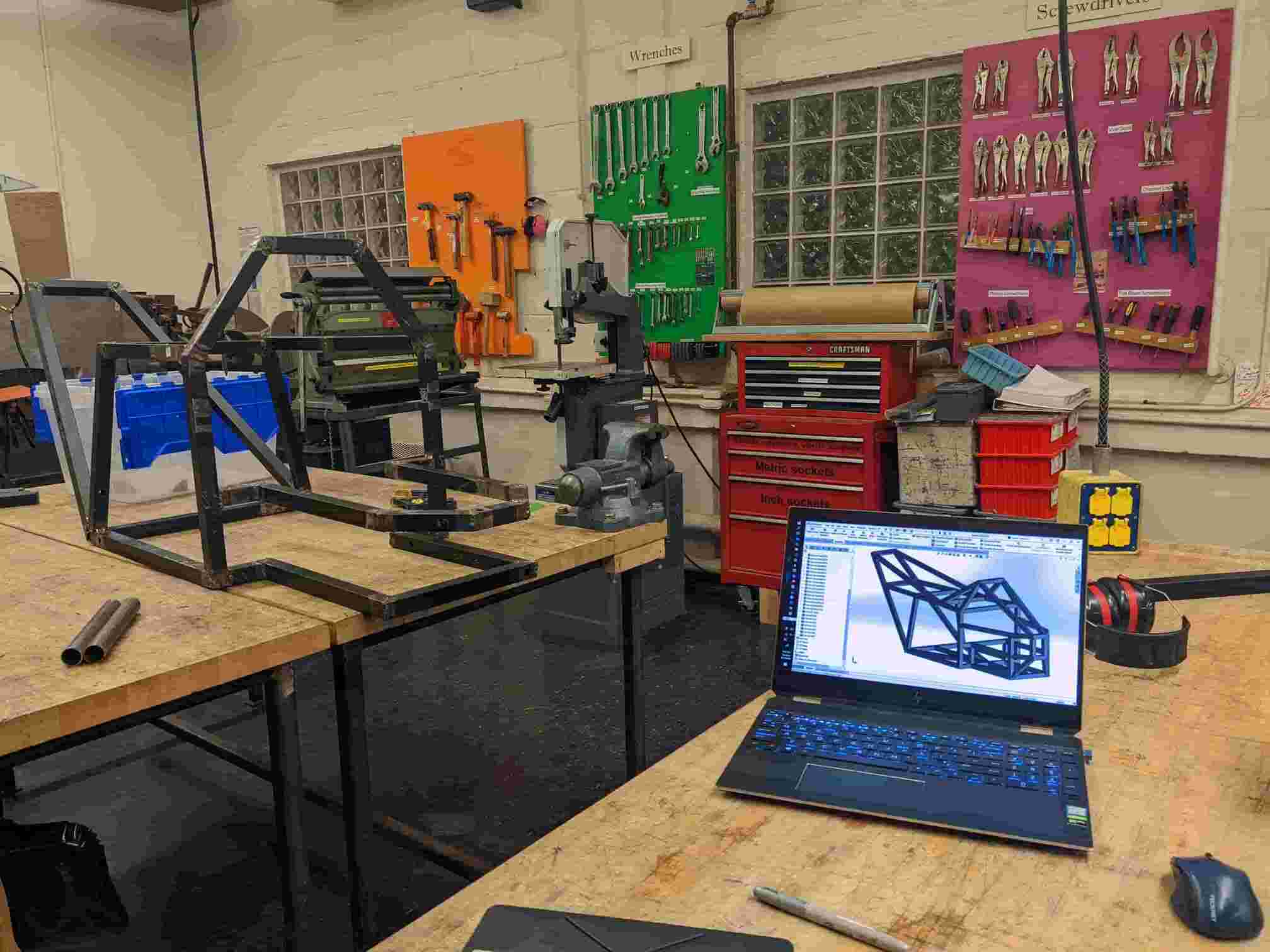
We began this week by breaking down the recycled desks and compiling them into piles of stock tubing. We did this by using an angle grinder and cut-off wheel, the whole process took several hours. Next we found a place to work and build our ATV, D-Lab. we talked with Dan, the acting shop head, he liked the project and got us started right away. Me and Raiphy both received welding training, on the MIG welder, and began welding our frame according to the CAD. This was my first time welding, so forgive me on some of the trash welds. We were also given access to a cold-saw which is exceptional at cutting our tubing at perfect angles. It is worth noting that for each weld we had to clear the paint off each peice of tubing this took about 20 mins for each piece of tubing.
-
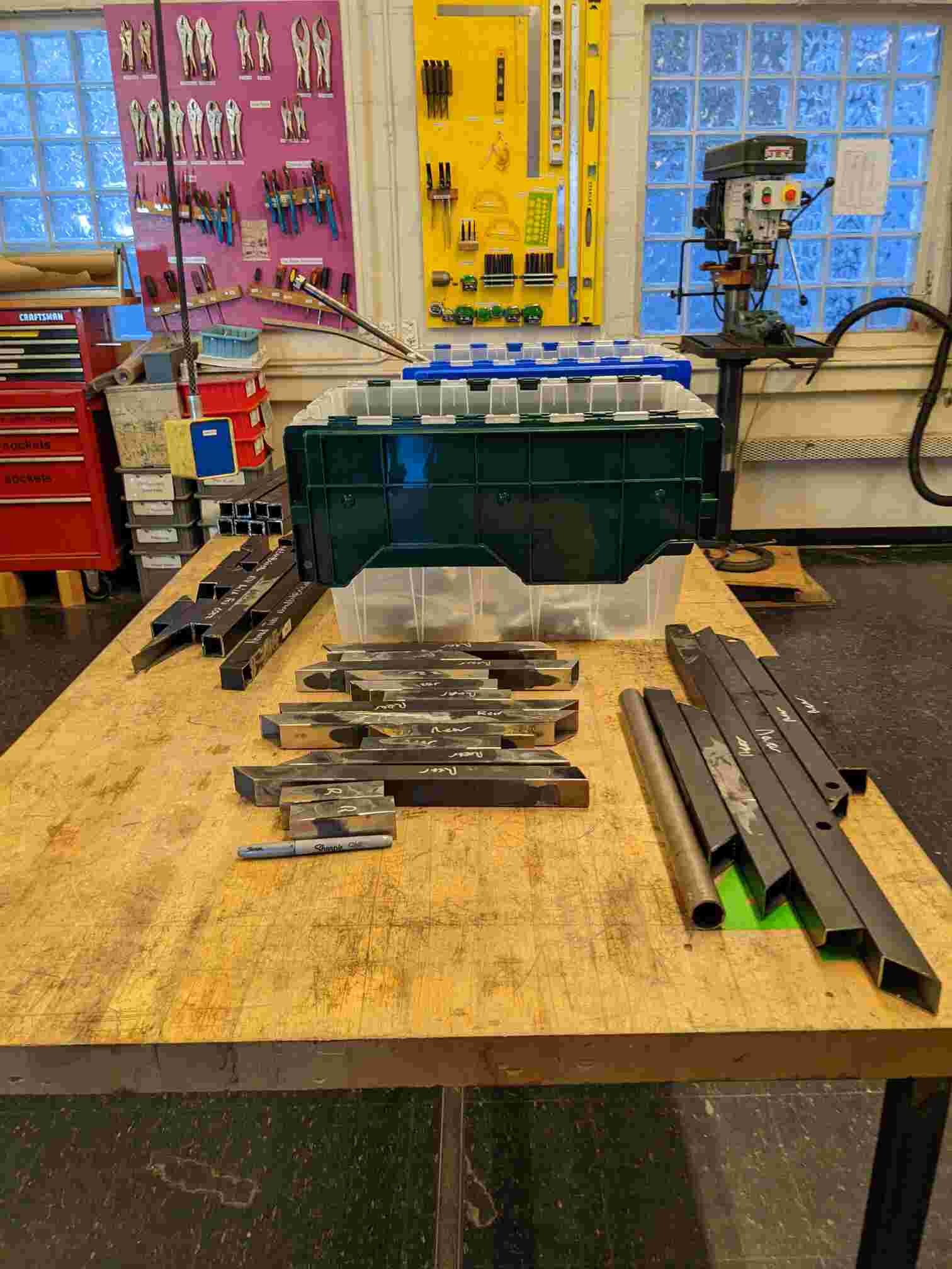
Week 2: Frame Continued
For this week we continued to work on the frame. Each day cutting our stock and shaping it into pieces for the frame. I devised a way to keep track of which things needed to be cut and assembled for each frame. I came up with a google spreadsheet and broke each weld/weld group into categories. I labelled them in the CAD so both me and Raiphy could see and work on them independently. In hindsight this was an important and very beneficial step. It helped track progress and made things easier to work on. This week and last we completed weld groups 1-4 and
-
Week 3: Frame Continued Again
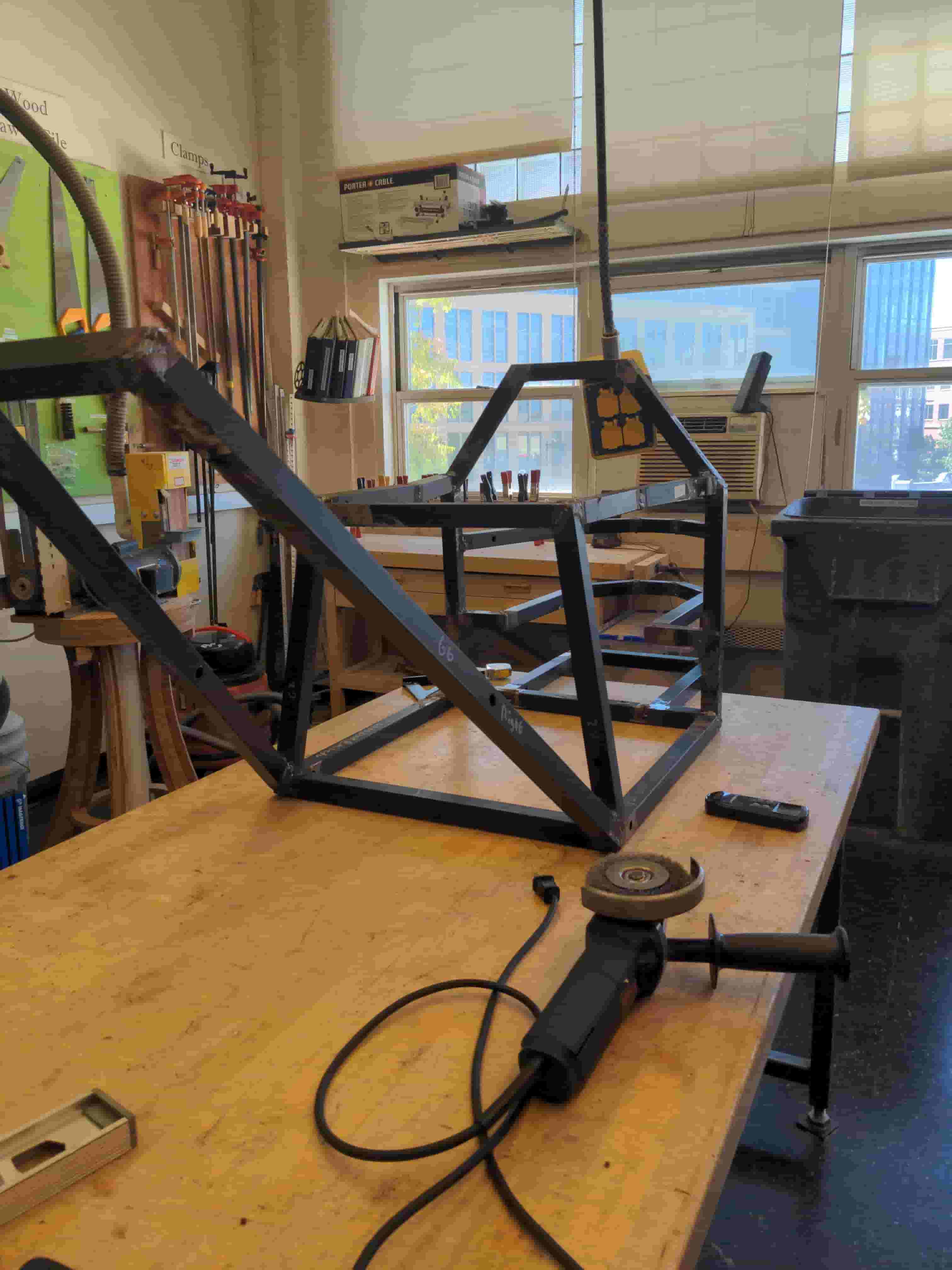
This week we continued our work on the frame completing weld group 5, 6, and 7. These took a long time because it had awkward angles and was quite long so it took a while to get rid of the paint. We also started cutting and shaping tubing for the 6 and 7th weld group. From this point forward when referencing cutting I am referring to a rough cut made with the cold saw for both length and general angle of each tube end. Similarly, when talking about shaping I am referring to the process of removing paint and cleaning up the edges of each tub with a file, preparing it to be MIG welded.
-
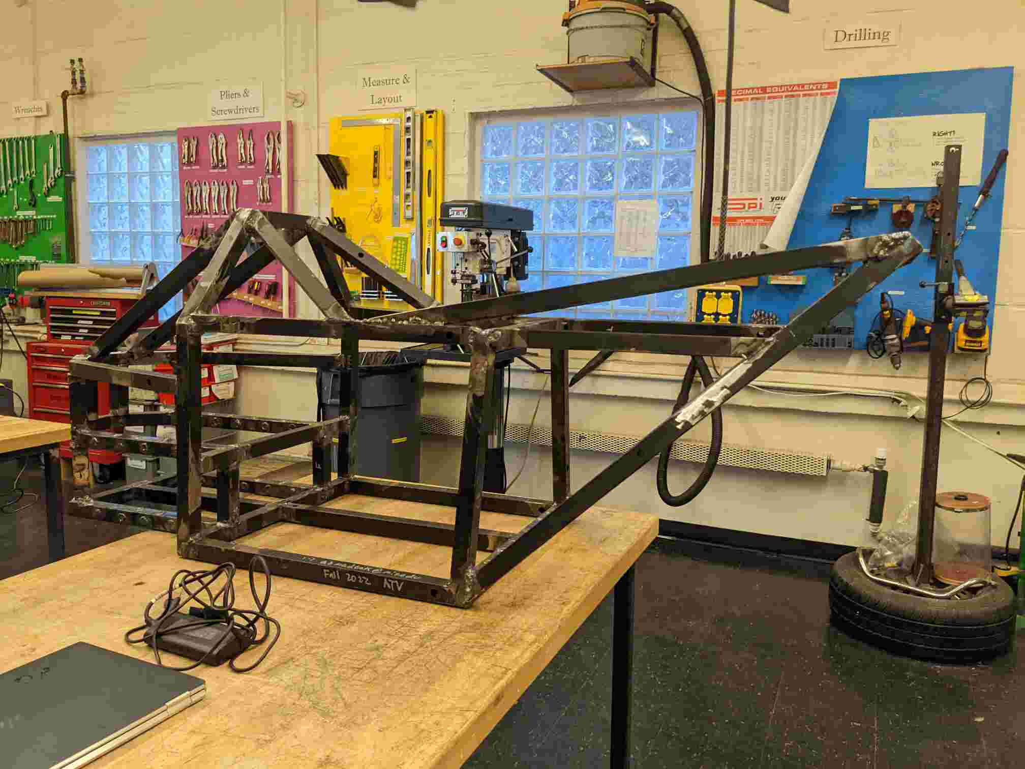
Week 4: Started Frame Bridges
For this week we finished off our work on the main weld groups (1-8), completing the main sections of our frame. We began working on the bridges. The bridges add more rigidity to the frame. Bridges are single pieces of tubing that connect between weld groups. This is in contrast to the weld groups which make continuous connections.
-
Week 5: Suspension Mounts Reinforced
Upon further inspection of our frame closer to where our suspension mounts we decided it would be best if we reinforced the area with solid round tubing we found in D-Lab. Raiphy did most of the work for this. While I worked on other weld groups. This was one of our more gruelling tasks it required a lot of effort. Hats off to Raiphy for doing this. I worked on cutting and shaping more bridges for adding to our frame.
-
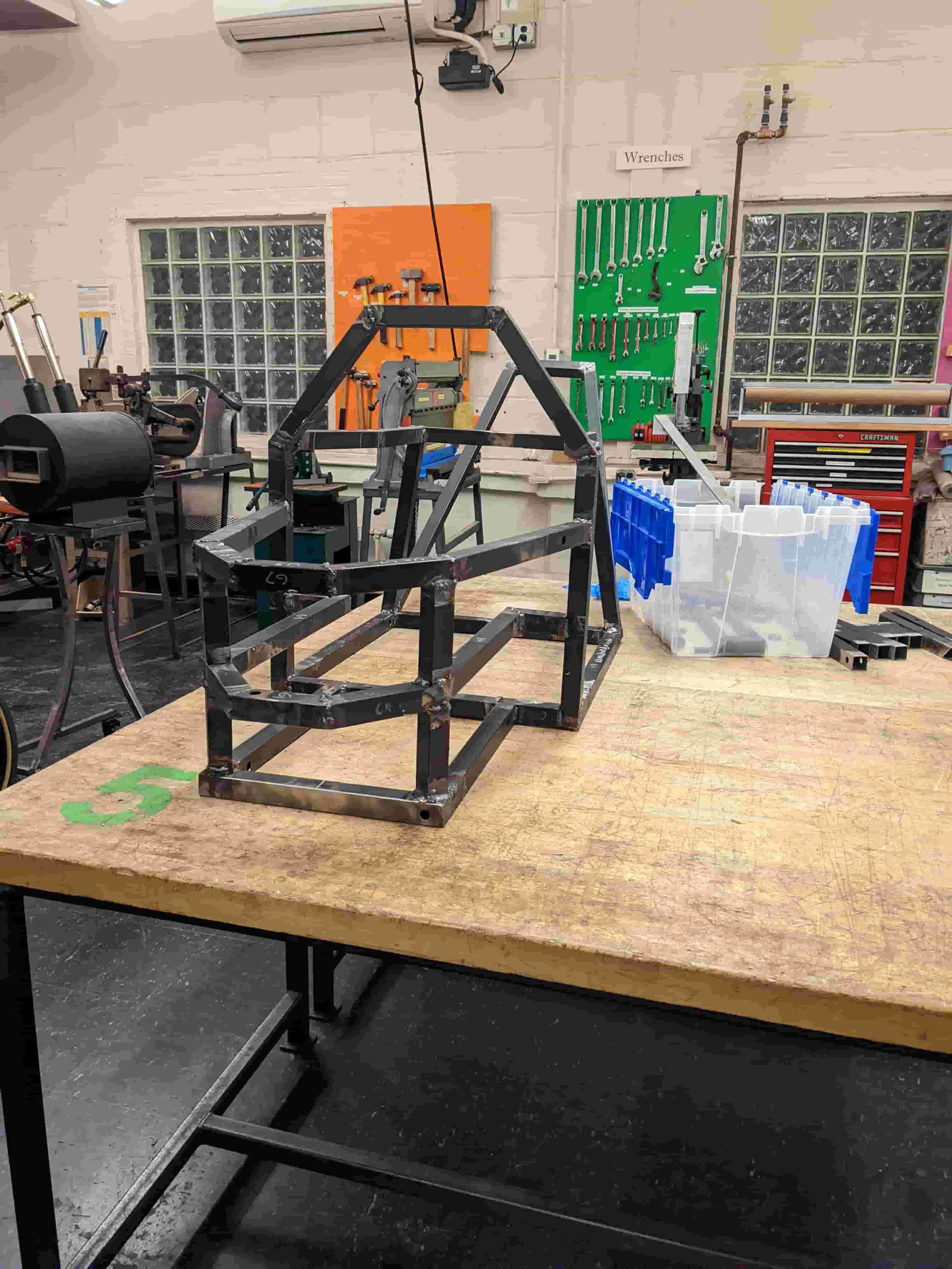
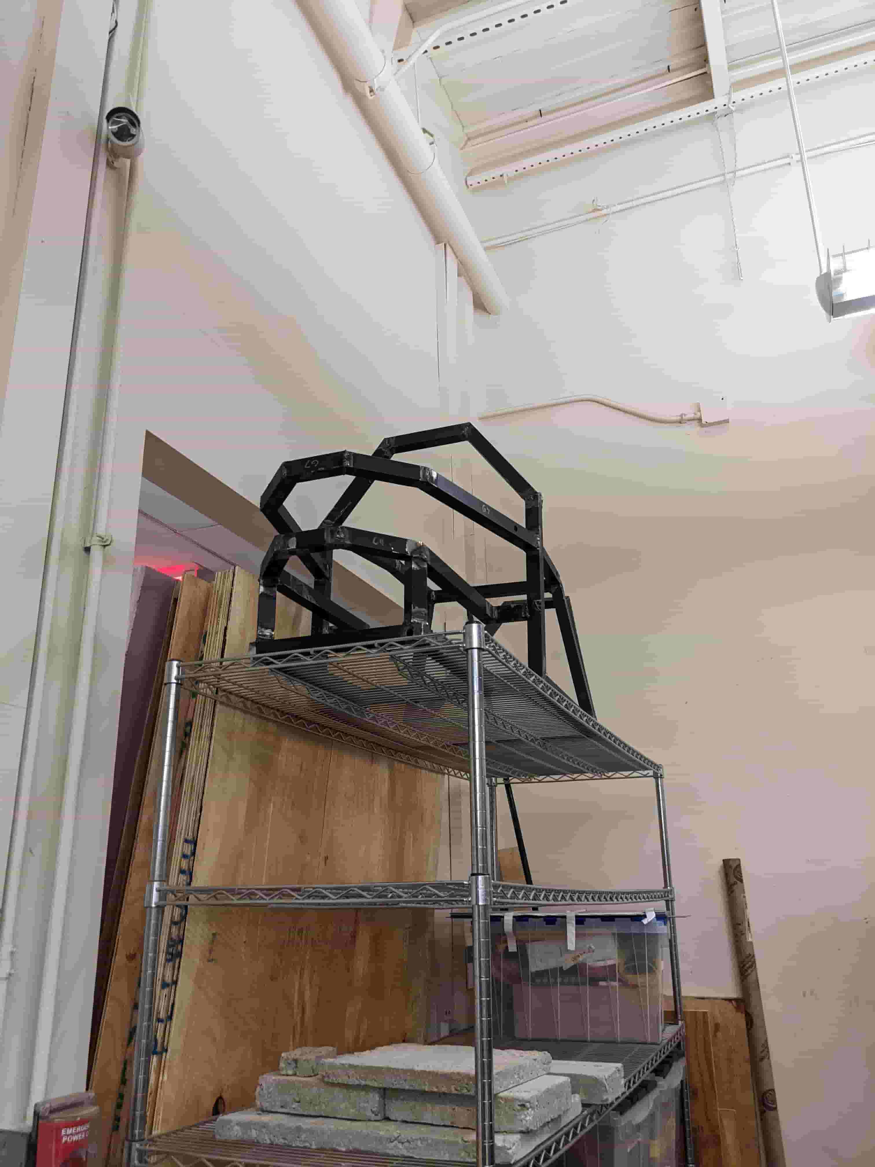
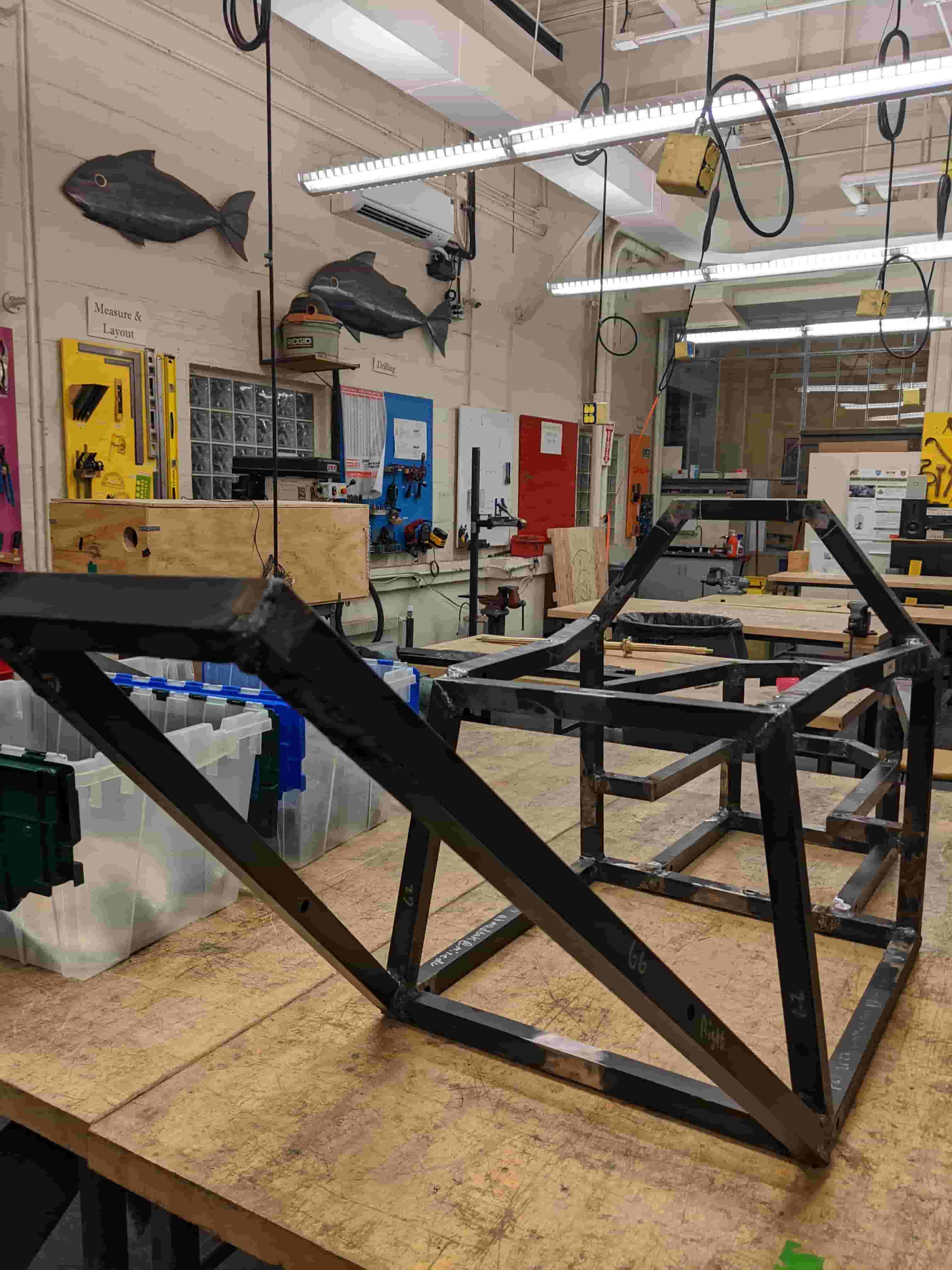
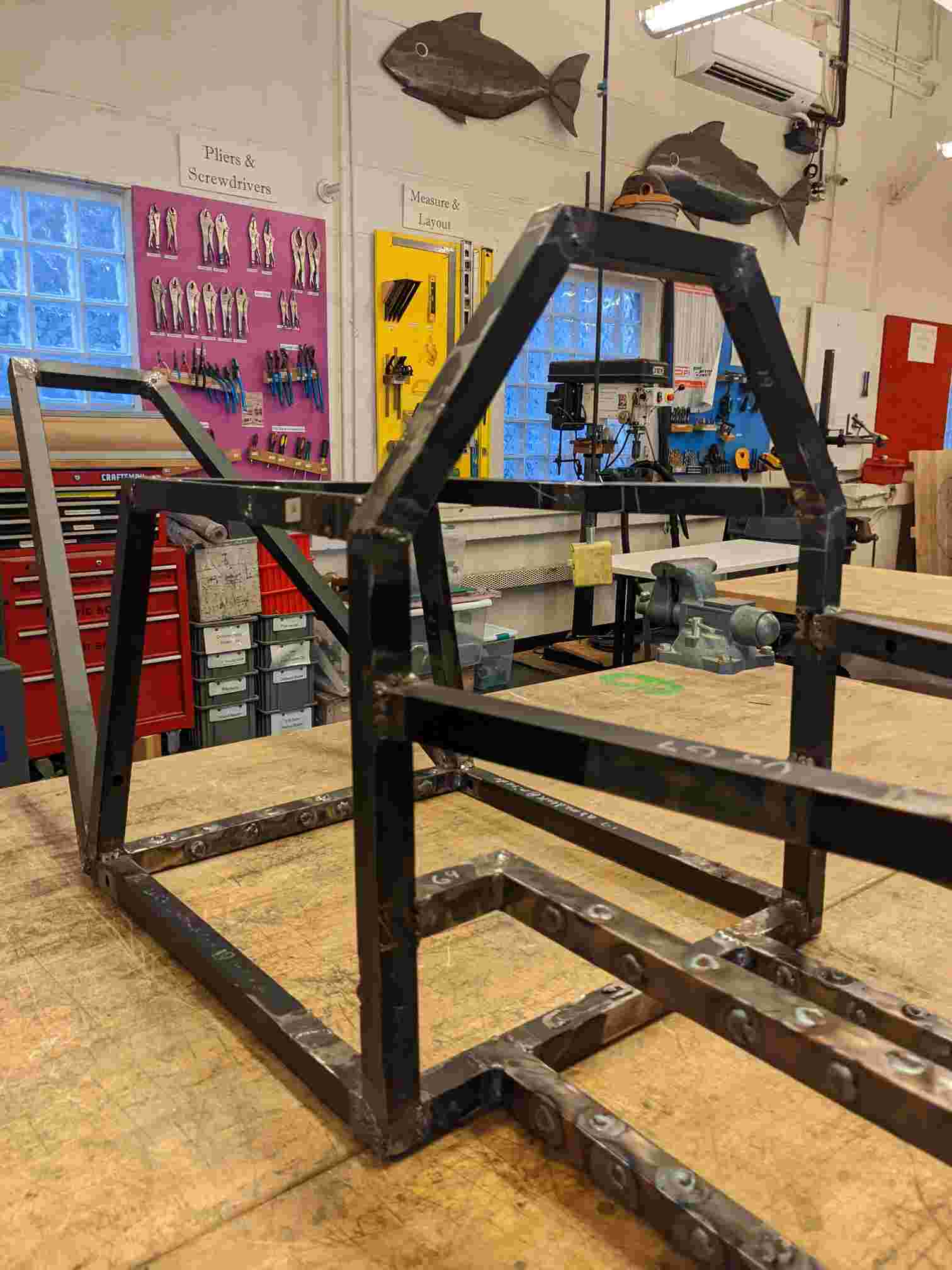
Week 6: Frame Complete
For this week we completed our frame. We managed to hustle and get the Frame fully complete it weighed in at about 50 ibs (~25kg). Later in the week we divided up the next tasks, and decided to set a goal of having a rolling ATV assembly by Thanksgiving. Raiphy was in charge of assembling the front suspension arms and I will be in charge of assembling the rear suspension arms, which contained more welds.
-
Week 7: Rear Suspension
Because I wanted more welding practice, I decided to cut, shape, and weld this assembly myself. For the first part of the week I spent each day cutting and shaping each piece of tubing to almost the exact specifications in the CAD. I was able to compete almost all the welds for the rear suspension arm.
-
Week 8: Audio Amplifier
The main thing I did this week, while Raiphy worked on the front suspension, was continue my work on the Audio amplifier from week 7. I want to be able to drive this ATV and play music. I managed to do some testing on a breadboard and settled on a configuration for the Audio Amplifier I liked. using 2 LM386's and some filters with feedback I was able to make a bridged configuration that seemed to outperform the LM4781 Audio Amplifier IC. I also water-jetted our suspension arm mounts.
-
Week 9: Front Suspension
The highlight of this week was Raiphy completing the front suspension arm main bodies. we still needed to add stuff for each the rear and front however we were at a point were welding based on the CAD deviated too much from real life. So we decided to wait until we were ready to assemble the rolling chasis before finished off the welds. Also at this point me and Raiphy were extremely comfortable working with Steal and MIG welding, our productivity was beginning to increase dramatically.
-
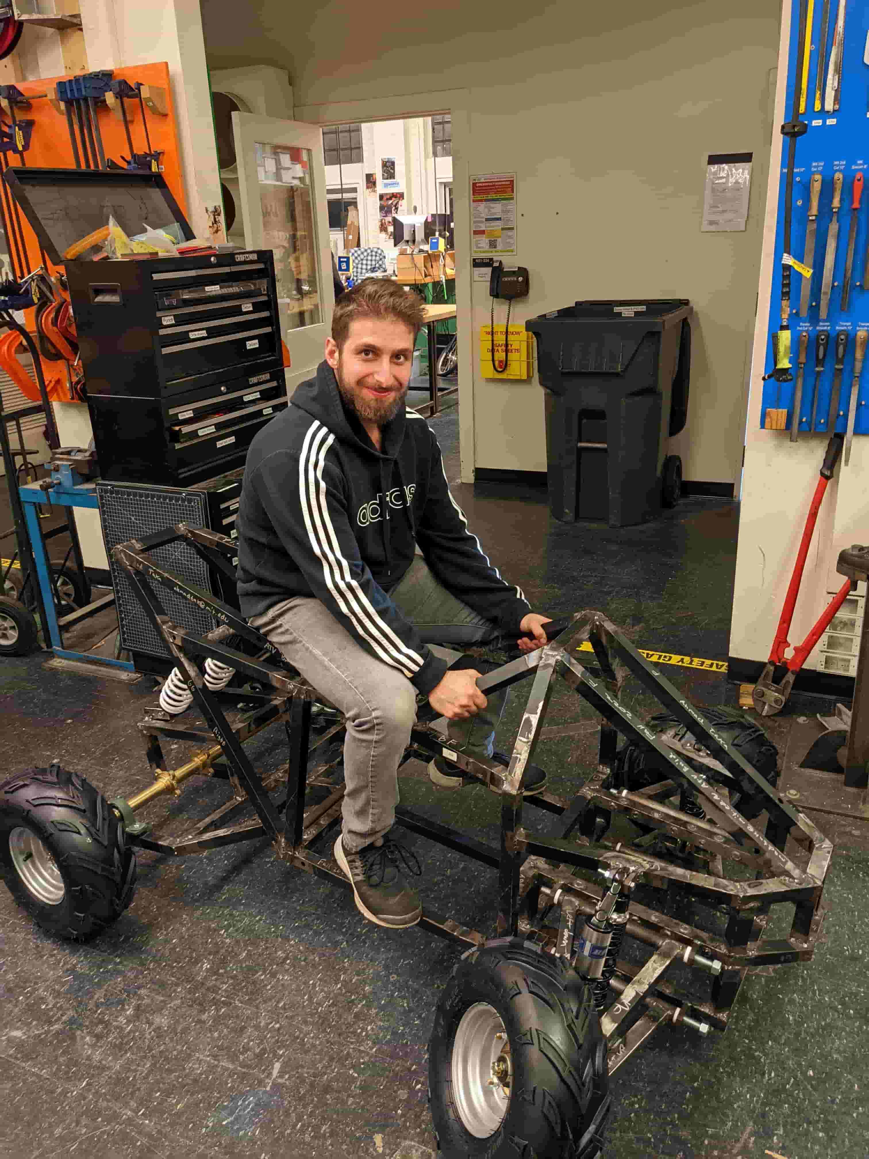
Week 10: Frame Assembled
In order to meet our deadline we needed to assemble our rolling Chasis. For this we needed threaded rods I made a trip to home-depot and got 1/2" threaded rods with appropriate nuts. I also purchased some small nuts and any other things we might need. We spent alost each day of the week at shop. We finished off any welds we needed for the Rear and Front Suspension arms. We hustled and worked late into the evening, we managed to assemble our chasis and it rolled. We met our first deadline.
-
Week 12: Playing Around with CAN and Starting Steering
After meeting our first deadline, I felt reassured on the trajectory of the project, gaining even more confidence that week we would indeed meet our goals. For this week I played around with CAN, exploring whether it would be feasible to integrate all the circuitry into a CAN-bus. This was largely successful (see week 11 and 12). I also started work on assembling our steering. I managed to water-jet a plate that gets welded to the frame in front. Again this was designed in a very simple so as to not take too much time to assemble.
-
Week 13: Steering Assembly Complete
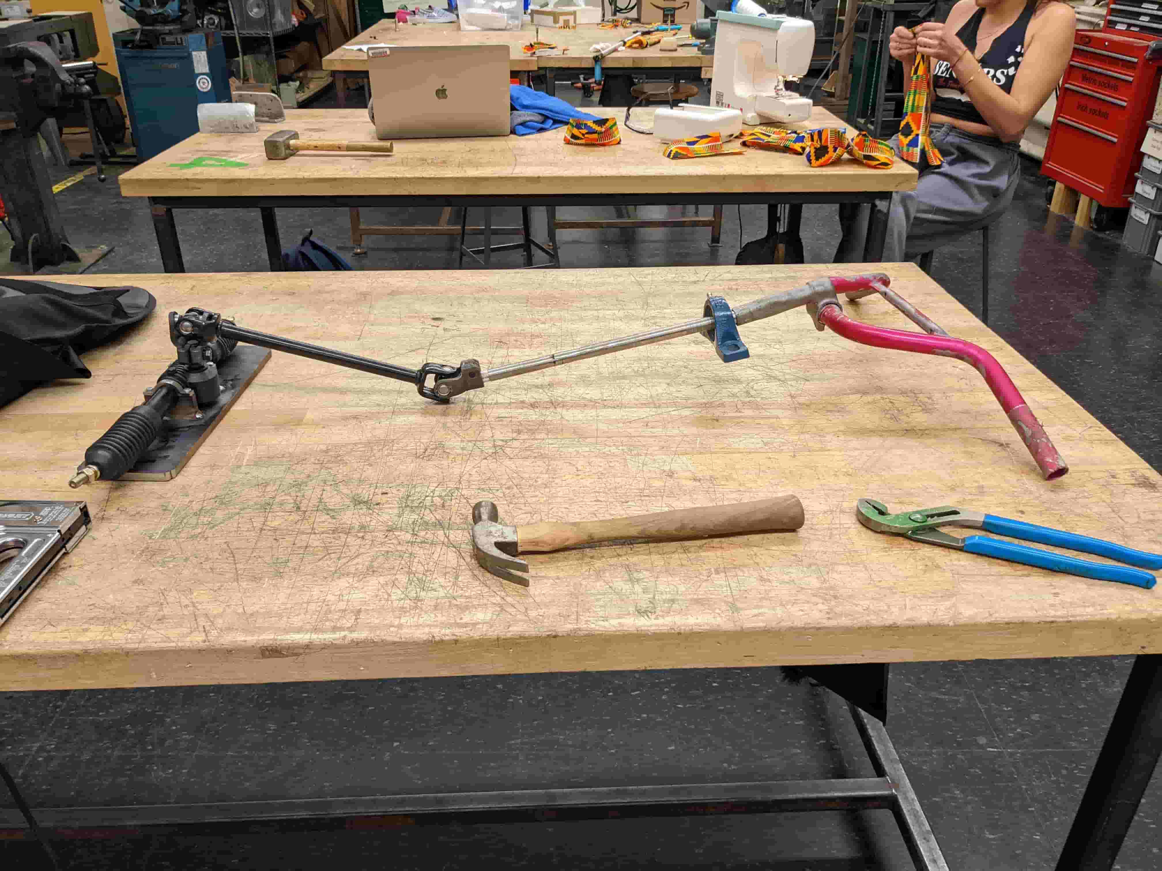
This is where things are starting to get super improvised. For this week I started by finding a steering handle. I was able to find a handle bar and the mount to along with it from a recycled barbie bike. I took the mount to the sand-blaster to remove the pink paint from it, for later welding. I did the same with the handle bar however it was taking too long so I stopped. After sand blasting I did some machining on the lathe to get the steering attachment that came with the go-kart steering to fit into the bearing. Then I started mounting it too the frame. At the same time Raiphy began to integrate the battery and Motor Controller.
-
Week 13: It Moves !!!!!!
This week had the biggest highs and the biggest lows. Once we got it finally moving we discovered several nearly fatal issues. First I learned the hard way that if there are aren't enough constraints to match the degrees of freedom something breaks, if something is used in an unintended way it breaks, and finally always do your math before you make it. With that in mind I can explain what happened during this week.
First we discovered that our steering was not able to handle the forces on it due to the weight of the vehicle and the torque applied by the handle bars. These forces caused the pinion gear, in the rack and pinion assembly, from the steering assembly to come off. This then caused the front tires to lock out become and misaligned the handle bars. So straight on bars no longer became straight on the road.
The next problem we discovered was that we didn't have enough torque to drive the ATV through a turn (when the steering was working) or go around on the road. This was seemingly a fatal problem as the only solution was to redesign the transmission, and somehow machine it to fit on the current assembly, an almost impossible task.
-
Week 14: "The Night is Darkest Before the Dawn"
At this point all hope seemed lost, however after a pick me up from my brother, Raiphy Jerez. I mustered up some energy and looked at the CAD for the transmission, after staring at it for a while I came up with a solution, it would be a pain to assemble but it would work. I came up with a way to mount another reduction stage, by taking advantage of our current motor plate which had been welded, in our Raiphy worked on solving the steering problem. He delivered spectacularly. We were able to work together and fixed minor issues that came up with either of our solutions. Within 48 hours our project went from barely drivable to smooth riding.
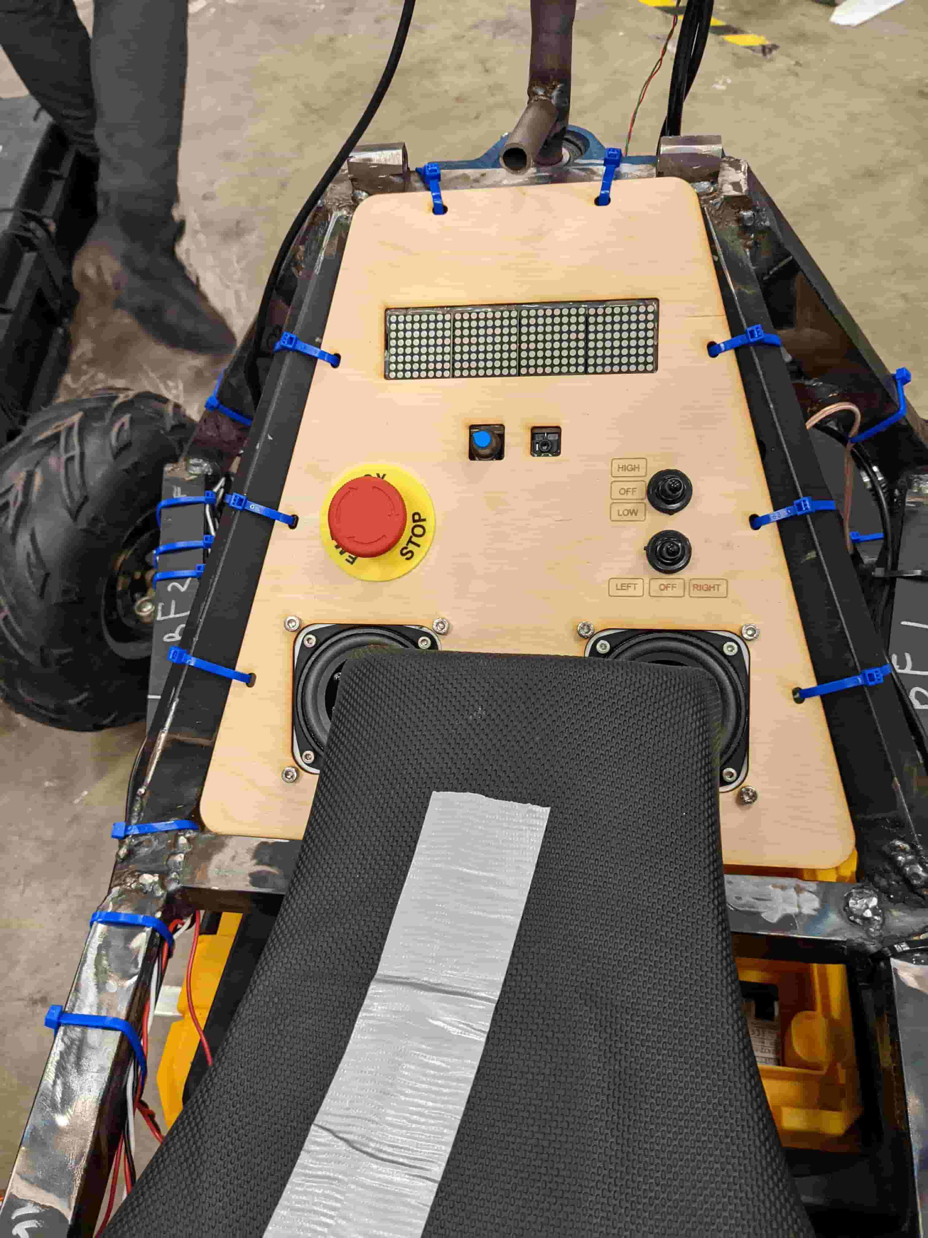
Once we go through this hurdle it was time to integrate our main Electronics additions we had been working on over the weeks. I redesigned my speaker boards from the previous weeks to be more modular and robust. I made an amplifier board for each speaker and an input board which handles volume and aux input as well as a mixing channel for the wave-form display. I milled out the boards designed a case for the speaker and panel for all of Raiphy's additions. We managed to integrate everything with the exception of the wave form display.
-
The Dawn
This is the final state of our project we did so much work. This is a video of me taking a stationary joyride and listening to music. This is beyond what I could have ever imagined when I set out for my journey at MIT. Doing projects like this, I learn not just a lot about the world around me, but also about myself. I learn what I am capable of when I set mind to do something and what I can do under pressure. Because of that these projects become more than the things I make.
2D-Design
Sprocket
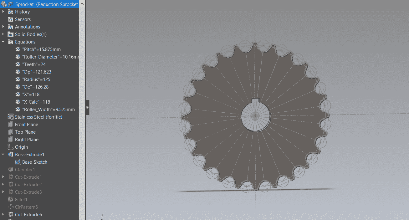
This first 2D Design is a sprocket. This is the part I am most proud of on our ATV it has been very reliable and is crucial to the functioning of our vehicle. It is also my most parametric CAD all a user has to do is input a few details about the chain such as pitch and select a number of teeth and SolidWorks will spit out a CAD for your sprockets. This can be used with multiple types of chains and fits perfectly for our chain which is #50 chain.
After making this CAD, I used a small section of our 3/8" steal sheet given to me by D-Lab, and took to the water-jet. I loaded it into the water-jet and set the path and watch OMAX do all the work for me. After machining it, we needed a slight chamfer along the edges of the teeth so it would grip the chain properly. So I sanded the sprocket down on a belt sander. After that we hammered it into the motor shaft.
In total I machined 3 Sprockets a 10T, 24T, and 9T. 9T and 24T for the first reduction and 10T for the second reduction.
Dashboard Mount
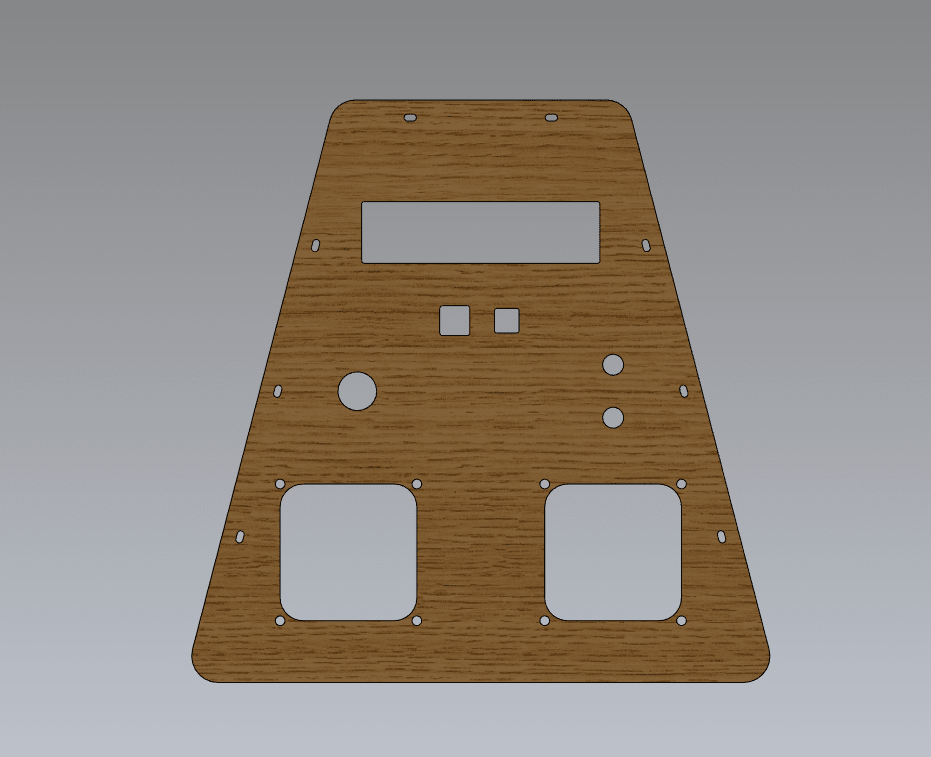
Another Notable 2D design is the Dashboard Mount. This Design is for all the things we want in our dashboard (e-stop, signal and headlight switches, volume and audio input). The impressive thing about this design was that it was guessed correctly the first time and I required no iteration in my design. What is on the ATV now is the first time I manufactured it. It was designed to be integrated with the MCP screen from my input devices week. And switches we found lying around. There are also mounts for the speaker enclosure.
3D-Design
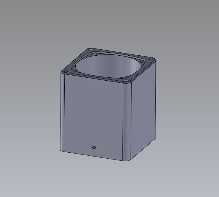
Speaker Case
In addition to the 3D design for the ATV, this design is a 3D printed design for the Speakers it was made to be as a large as possible, to get a flatter frequency response curve without interfering with other sections of our ATV like the battery. I printed it with White ABS.
It was fairly straight forward to design and assemble. I designed in tolerance for the screws to screw into the ABS plastic. This is not usually a good Idea. But in this case the Assembly just needed to last a couple of days.
Electronics-Design
Speakers
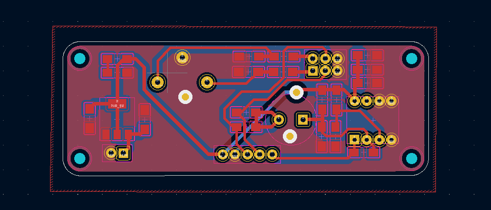
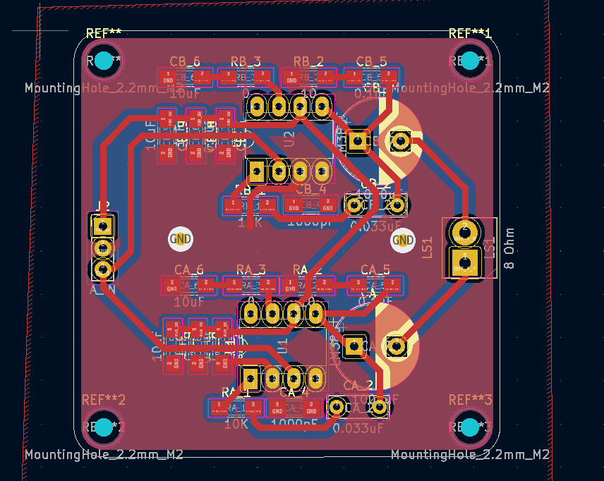
Following my progress from the previous weeks I milled out two new versions of audio amplifiers from the output devices week. The amplifier board (on the right) has a larger ground plane which should help with some noise and it also adds more gain (because I have more powerful speakers). This should allow the max volume set by the potentiometer to be very high. The trade off however is that there is larger audio signal distortion.
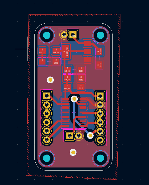
The next thing I did was separate the input control (volume and aux) from the amplifier and screen driver board. This also helped mitigate some noise as well as aid in the debugging process and made everything easier to integrate in the end. I added a breakout for 5V and all the audio channels (left, right, and mixed)
Programming
Waveform Display
This was also a continuation of my previous weeks assignments (input devices). In this version however I made the board simpler and modularized it. Again for debugging reasons.
This is the only thing on the ATV I regret to say did not fully work. During debugging I discovered that the 5V regulator on board was outputting 9V and fried the MCU. At that point it was too late to do anything about it. So I cut my losses with screen. I attached my code and for the board and also have a video of the circuit working on a breadboard in week-9. It is worth noting that this was inadvertently a good thing as it turned out much the low audio quality in the previous week was due to LED matrix screen.
Final Thoughts
Special Thanks
This project could not have been completed without the support of the HTM staff and Neil's support. Special thanks to Anthony for the times he helped me debug Audio problems. We would also like to thank Jack and Dan from D-lab for putting up with us during this project. D-lab became a second home to me during this project and Jack a great mentor. Thanks to all the other students in HTM for a great semester.