Final Project,
Ideation Phase: My final project idea so far is a bar soap 3D printer. I really love bar soaps and being able to make ones instantly
after feeding in a soap mixture would be really cool. Looking at past final projects,
I saw someone try to make a toothpaste extruder so ideally my project would be along the lines of extruding liquid soap and then being able to cure it instantly as the printing occurs.
There are different methods of curing soap and soaps that use lye definitely take more than an order of minutes to cure (it's usually months) so I'd want to work with a soap base that didn't have that long of a curing time,
and ideally had a short setting time so I'd be able to layer on top of it and achieve cool designs.
After talking with Neil and Anthony, I fleshed out my final project idea to be a 3D printing soap pen. What does that entail you may ask? Well, let me begin:
My starting point for ideating the pen was a hot glue gun. After all, a hot glue gun allows the user to extrude a material and dries quickly enough that it can be layered on top of each other. Obviously, that has to do more with the
property of glue than the mechanism itself but we'll get to the material properties of soap later. After ideating and then discussing with Anthony about feasibility, I decided my ideal 3D printing soap pen would have a touch or capacitance
sensor that the user touched while using the pen to control when to extrude and extrusion rate. The touch sensor would more directly be giving input to a motor who would then control the extrusion of the pen. The pen would also need
a heating element, sort of like that of a hot glue gun but at a much lesser temperature due to the melting point of most melt + pour soaps. The pen would have an overall ON/OFF switch and when ON, the heating element would also be on, regulating
the temperature of the soap filament inside. I decided I could make my filament be solid melt + pour soap base poured into cylindrical molds so they could easily be inserted into the pen.
My plan of action so far is to first experiment with the touch sensor and see how I can use it to control the motor. I will then have to decide on the motor's mechanism in terms of how it's pushing down the soap filament. From there I would
need to do some material experiments to decide on the nozzle shape and functionality --> what I mean by this is that I'll need to figure out the perfect soap mixture that emulates the properties I need, mainly a semi-solid consistency that
can quickly set and be smoothly extruded but also something that can be layered on to build on top of previously printed things. Once that happens, I can create the final enclosure and make a flexible PCB that can be stored inside the pen.
It's a bit optimistic but I hope it can work. If I find that the material tests aren't working out, I may settle on just using hot glue gun sticks to test my idea which will hopefully still be novel as I think my mechanism itself
is very different from the typical hot glue gun.
Currently, I explored the two dynamic inputs and outputs of the project in weeks 8 + 9 : a makeshift touch sensor and a servo motor. Following that, I plan to order a low temp hot glue gun
and modify the maximum temperature to be 125°F or closer to the melting point of the soap mixture. Once I have the circuit set up, I can then design the enclosure and the mechanism to control extrusion.
Ideation Phase: With T-6 days before the final project was due, I decided I wanted to change the idea I had been set on for the last couple weeks. A lot of it was due to the fact I hadn't started on the mechanisms and enclosure yet and I didn't feel like I would be able to do my idea justice with the time I had left. With this in mind, I decided I wanted to do a temperature controlled coaster! The inspiration was simply that I love a good bev (e.g. beverage) and having it be at the ideal temperature each and every time would be lovely. While I'd seen devices before that could heat things up / keep drinks warm, I hadn't encountered temperature specific coasters, especially not ones that could cool things down. That's where the Dream Coaster comes in handy.
Electronics :
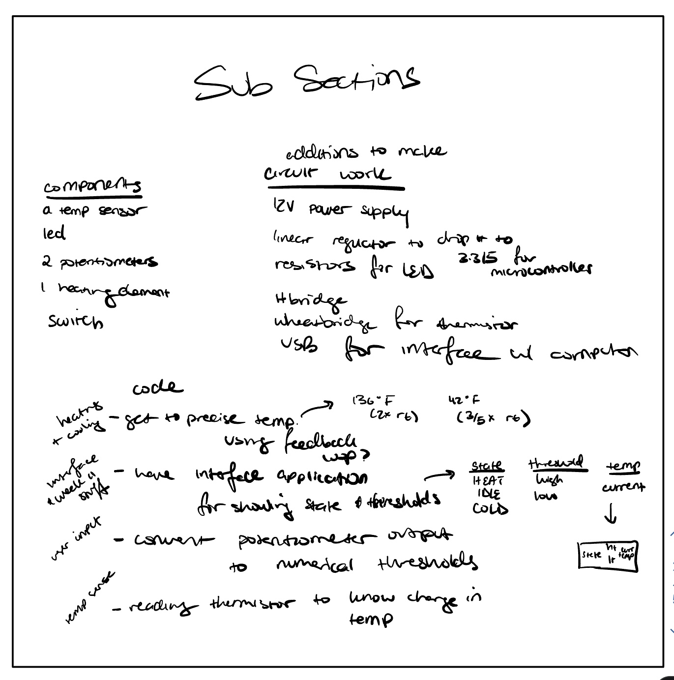
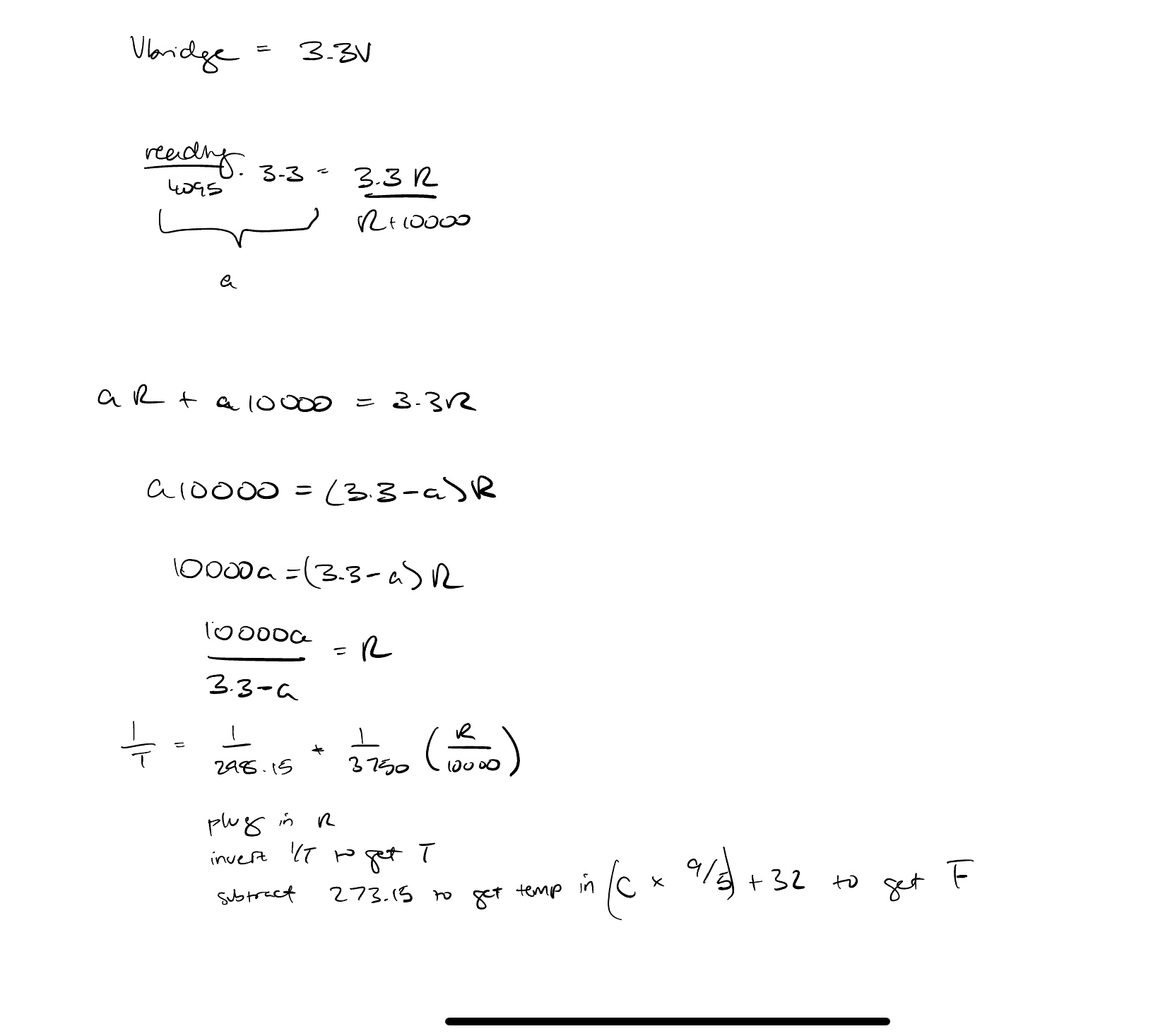
Above are the main elements that would be present in my final circuit. To start off, I started breadboarding my circuit and made sure that the thermistor measurement and potentiometer worked like intended. I used the thermistor in series with a 10k resistor to create a voltage divider. With that, I would calculate the voltage dropped across the thermistor and then use that voltage to determine the variable resistance of the thermistor and its corresponding temperature.
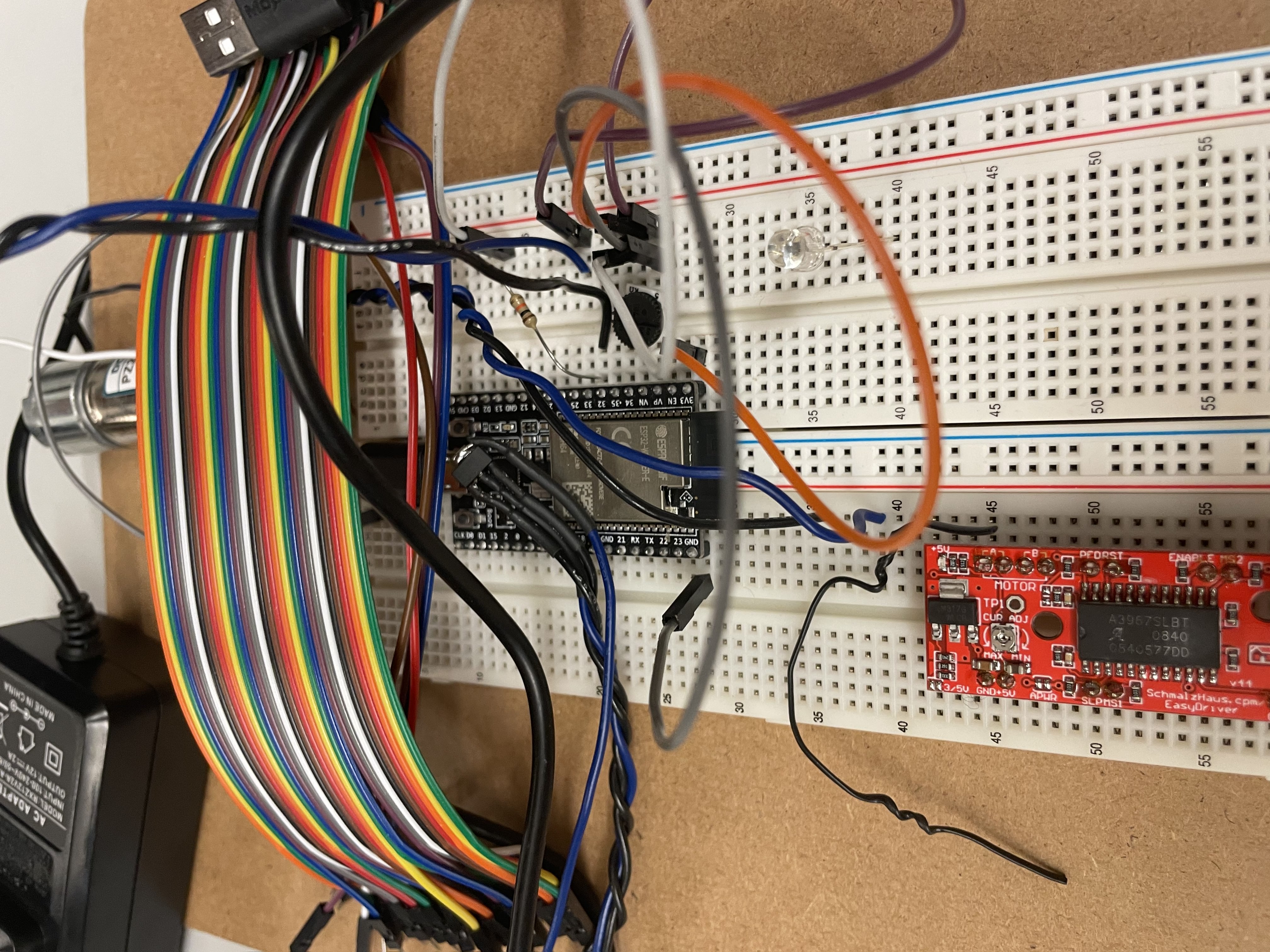
Unfortunately, at some point my breadboarding had to come to a pause. I intended to use a Hbridge to reverse polarity on my Peltier to determine if it should be cooling or heating. Since my Peltier unit was set to arrive on the day before presentations, I used a DC motor to breadboard instead. Unfortunately, the only Hbridge adjacent device I had was this stepper motor controlling chip which neither me or Anthony could make sense of.
This prompted me to get started on PCB design. I printed about 3 or 4 versions of my PCB. In the first iteration, I had forgot to connect 3.3V to my Arduino. In my second one, I accidentally tore off the footprint for my ESP32. In my third one, my Arduino simply refused to turn on regardless of how much board surgery I attempted. In my fourth one, 3.3V and GND were apparently shorted in many places due to a shaky mill but luckily, I was able to surgery my way out of that pickle. The three pictures below show my final schematic, layout, and overall PCB.
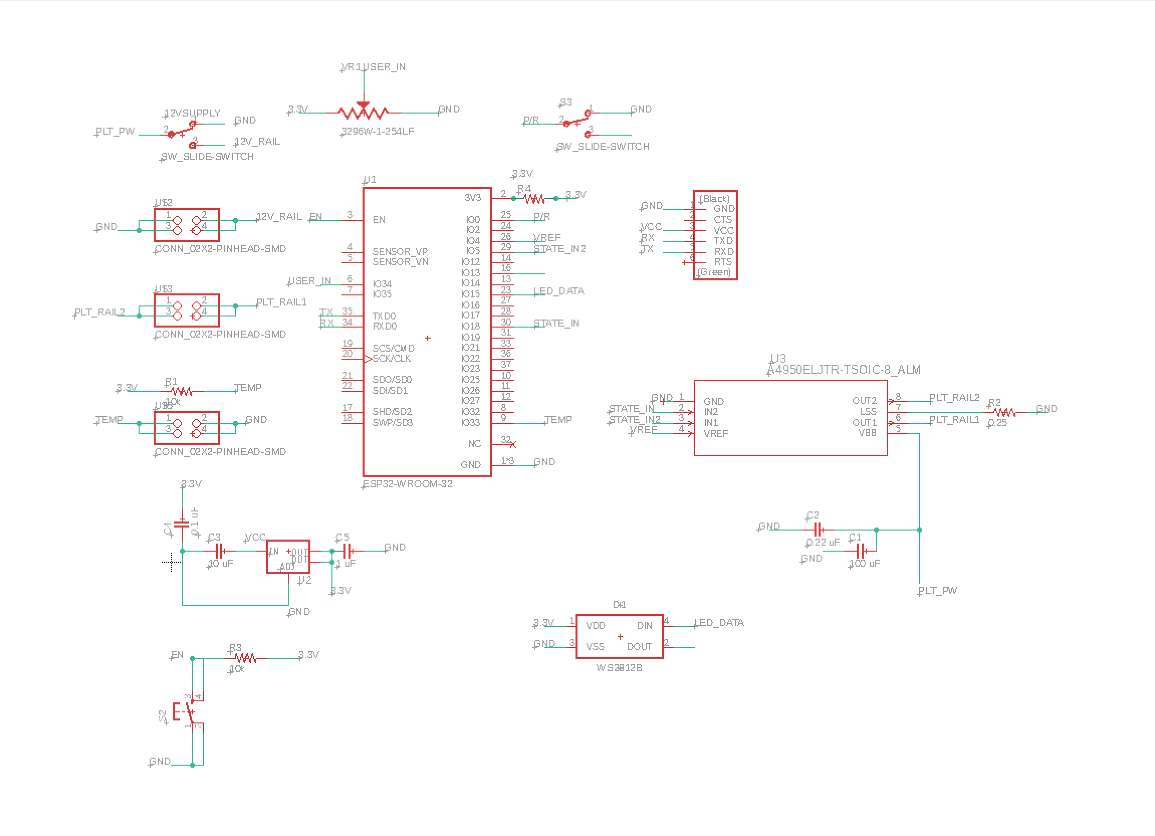
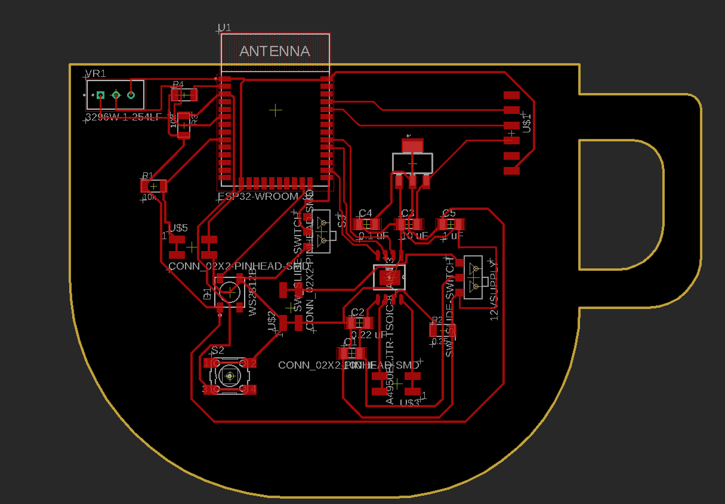
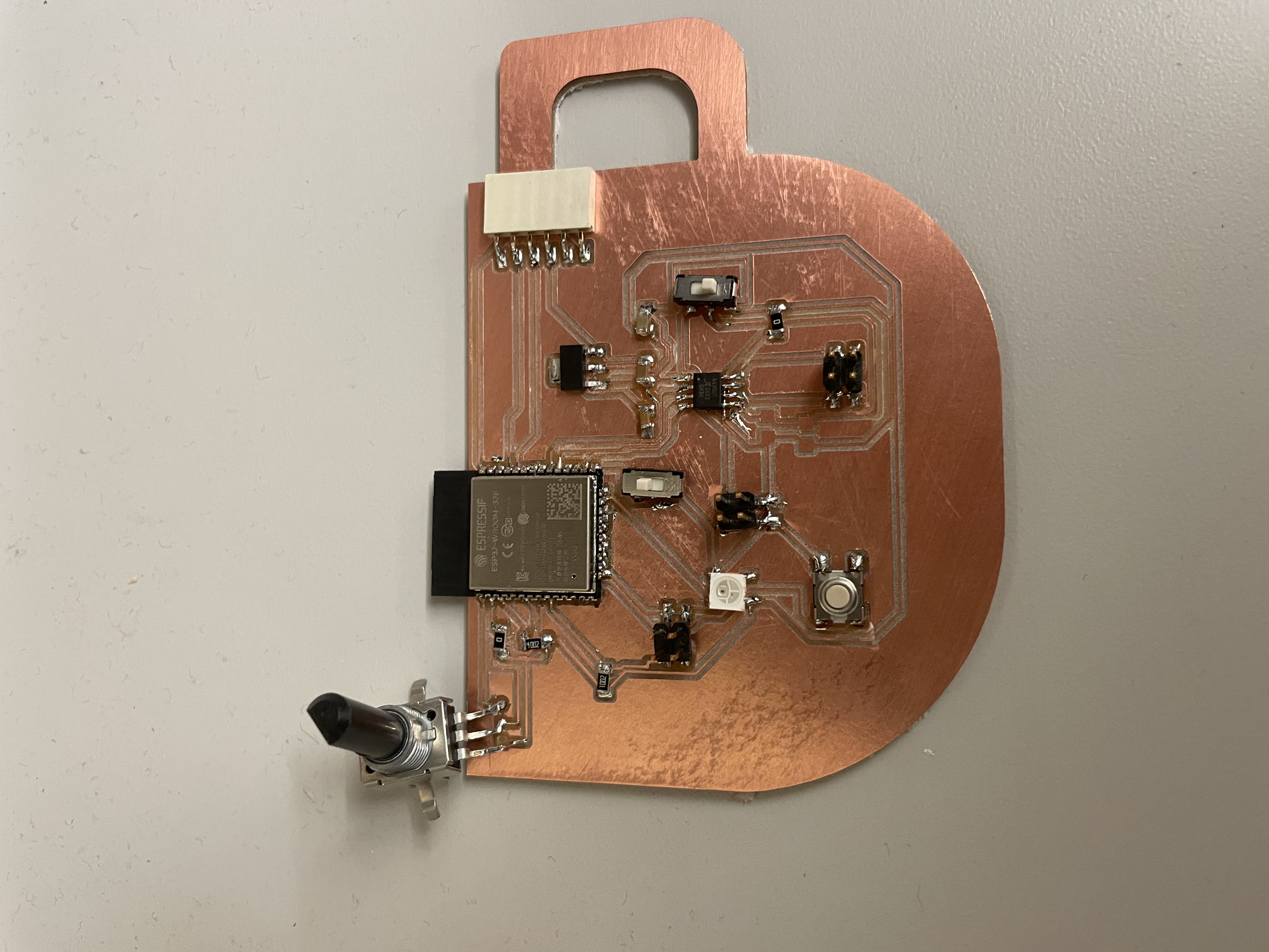
In my PCB there are three connectors in place of footprints. These were for the 12V power supply, the thermistor connection, and the Peltier connection. This allowed me place the thermistor on the surface of the metal plate so it could detect temperature accurately and also allowed me to place other items in substitute of the Peltier module for workshopping functionality.
Physical Structure:
The main components of my physical structure were my heat sink, overall enclosure, and metal plate. The making of my metal plate is documented in my week 13. To make sure my enclosure and metal plate ended up being the right dimensions, I modeled the entire model of my project including the Peltier and heat sink and space for wires connecting to the PCB.
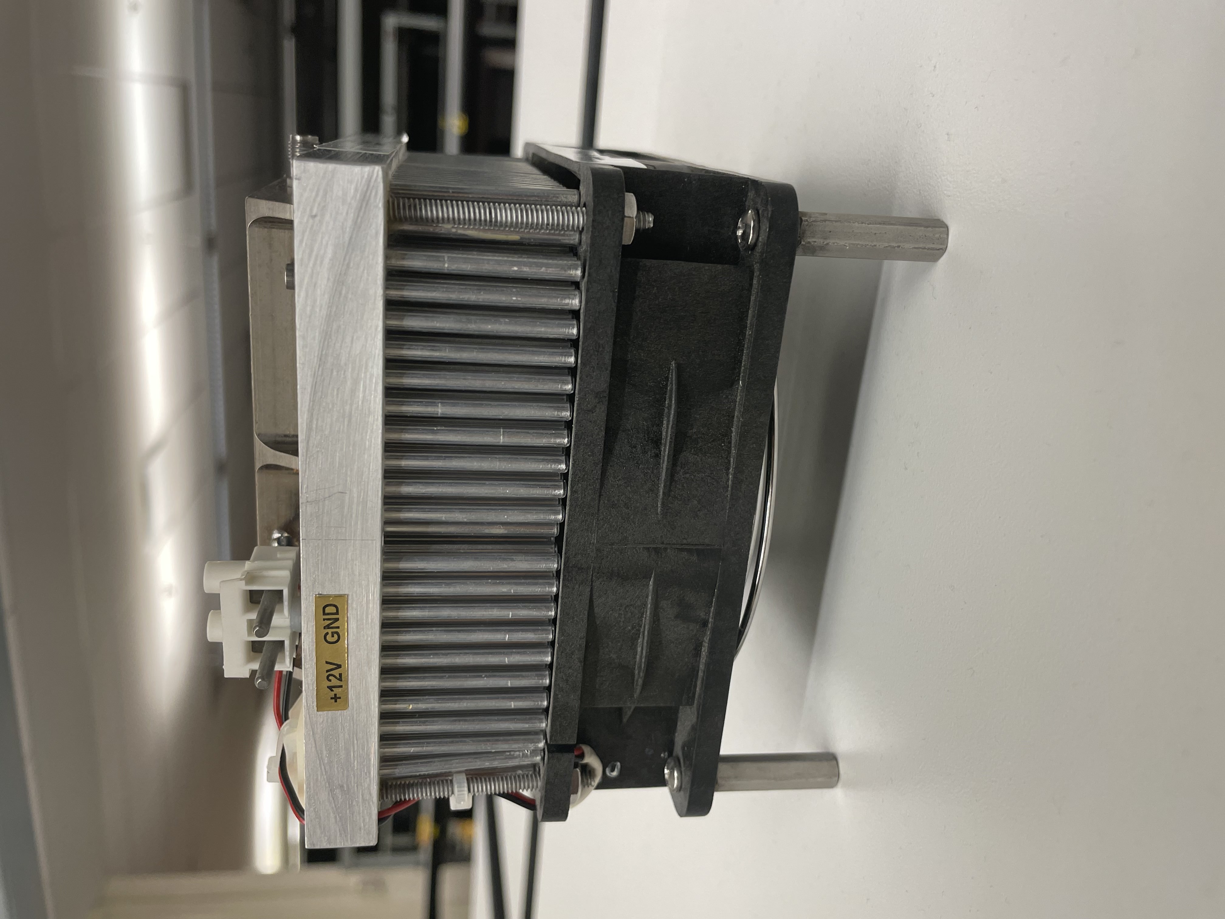
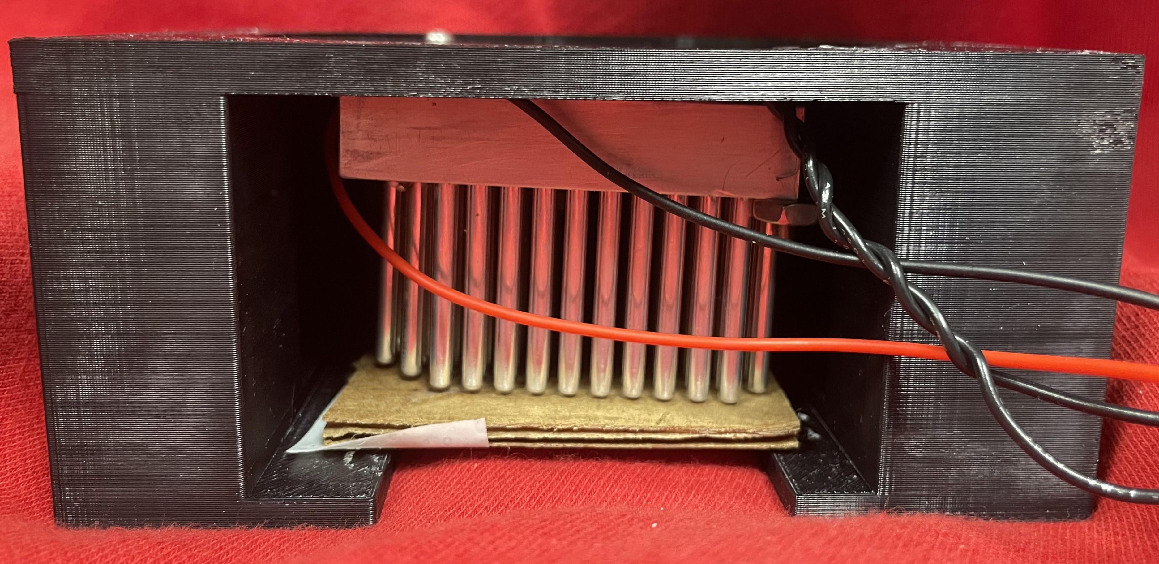
Originally, I had based my enclosure off the size of the heat sink I'd scavenged which resulted in a 3D print that would take 18 hours and 25 cubic inches of material. Anthony advised against this and I had to agree. I scaled my enclosure down and cut my heatsink down to size. Ultimately, I ended up with a 3D print that took 7 hours and 14 cubic inches of material.
The pictures below show the heat sink contraption I started with and the compact heat sink I was left with after taking the whole contraption apart and cutting it.
Le Finale: With T-10 minutes to my presentation, I accidentally shorted my ESP32 3.3V to 12V. Needless to say, the bad boy was fried. I was freaking out on what to do when I remembered I had the breadboard version. Obviously, this one didn't work in the way of an automatic feedback loop like the PCB did but it was enough to show the proof of concept of my idea. Unfortunately, I had been way too stressed to take videos or even pictures of my device working but enjoy these miscellaneous shots of my device working with a power resistor (this heats up when a certain amount of voltage is dropped across it) in place of the Peltier and its associated interface screenshots.
All in all, I wish I had taken this class with a lighter semester so I could have poured more time and effort into it but even so, I'm pretty proud of what I accomplished and also seeing everyone else's accomplishments. It was so cool seeing what people had worked on week to week and even more cool, seeing what all their work culminated in during presentations. I especially want to thank all the teaching staff for making HTMAA happen and forever grateful to Anthony for all the help he provided and remaining calm and helpful despite pulling an all-nighter with two sections of students crammed into the EDS lab.
And with love from my electric coaster and I during this holiday season, I say a farewell to HTMAA. 'Tis been great : )
- Alex