Week 2,
Ideation Phase: The assignment for this week was to mill a PCB. A PCB is a printed circuit board,
and in this case, we were printing it by milling a plate with a copper layer and non-conducting center. The mill would remove copper according to the design we gave it and would then result in
a small circuit. I'd never designed a PCB before but this week wasn't really about doing so. Instead, we were given an already-made PCB design so there wasn't much ideating to be done.
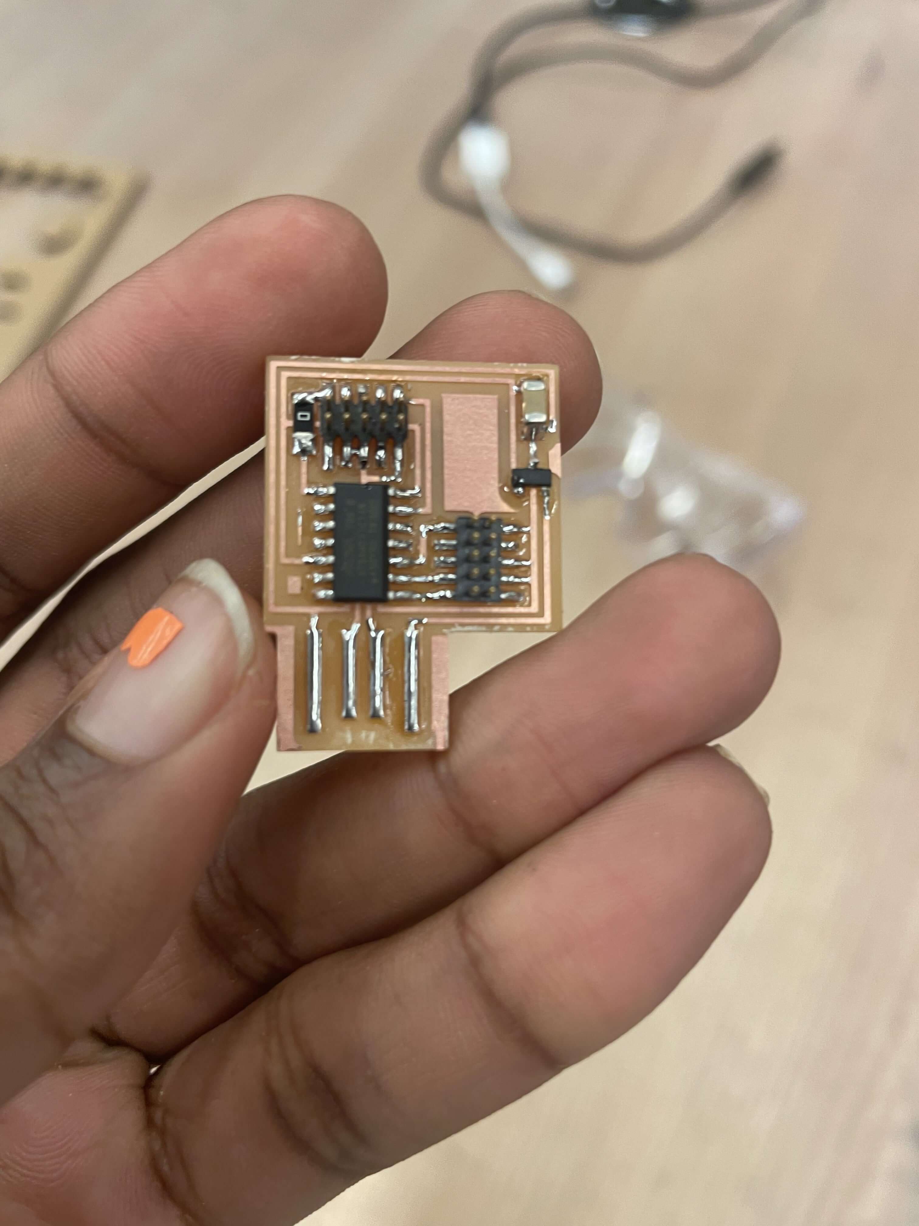
The EECS group characterized the PCB and with those settings implemented, I began the milling process. (Below is a spoiler of my final product.)
Design Phase: The milling process was relatively easy.
I got my material and placed it on the milling bed of the Othermill and used the software to focus my mill and validate my tools. There are two tools that were used throughout milling this board:
1/32 milling bit (I am unsure of the official term) and the 1/64 milling bit. The 1/64 is used for the tinier traces while the 1/32 is used for the slightly larger traces. Using a 1/64 for the
whole process is possible but would result in a board that was very hard to solder parts onto.
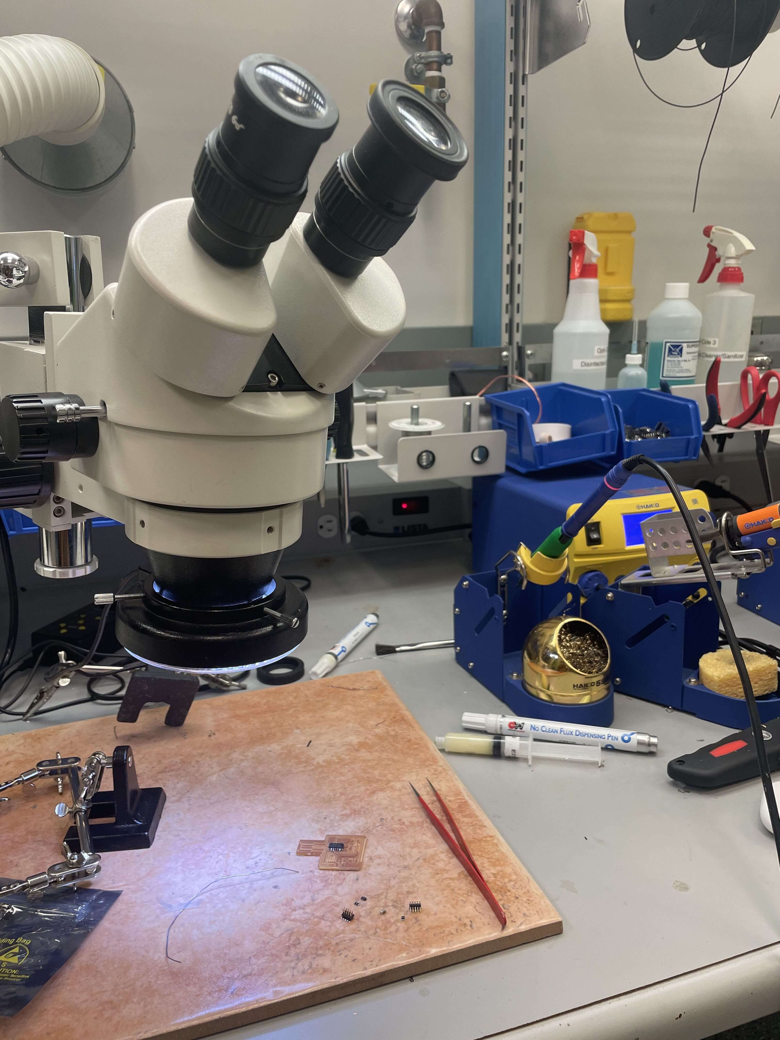
Speaking of soldering, I have soldered before so this wasn't new to me. What was slightly new was soldering under a microscope. I say slightly new, not because I've done so before, but because I still
haven't officially done so now. Instead, I would use the microscope to position my parts or to check how my soldering looked but it wasn't an integral part of my process. Even so, it was pretty helpful to
see the soldering in that much detail, especially because we were soldering tiny parts on a very small board with even smaller traces. One lesson I learned during this process was to not drink a large frappucino on
a somewhat empty stomach before soldering. My hands were so shaky which led to some newfound experience with both desoldering wick and a heat gun used for desoldering.
Final Product: Finally, the time came for programming. After I'd soldered my board, I had to make it useful. With Anthony's (my TA) help, I used a
microcontroller to turn my small milled board with shakily soldered parts into its own powerful microcontroller! This process was quite simple and involved running two commands in terminal.
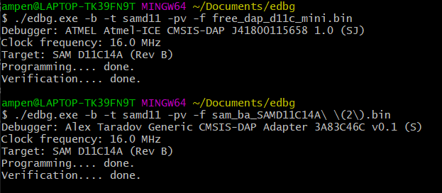
Just like that, a milled microcontroller was born.
- Alex