This page is meant to keep track of the progress I make on my final project throughout the class.
On many occassions I will repurpose or combine different weeks to help realize my final project design/functionality.
week 0: MIDI hand controller
ideation.
model pass [0]
I've been getting familiar with live coding music performance. Only issue is that I generate code slower than I come up with music ideas.
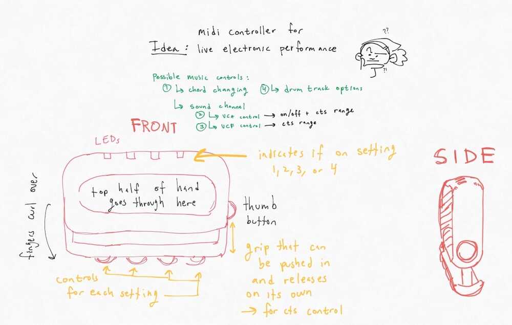
Final project idea?
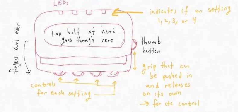
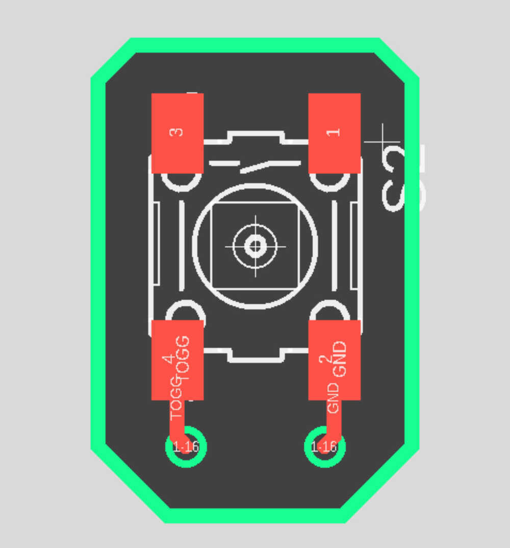
As shown in the picture, possible control features for this device could include [1] chord changing, [2] volume (VCA), [3] filter (VCF), and [4] drum track controls. A user would stick the top part of their hand through the opening of the device and curl their fingers over the sliding press control on the bottom. There is also a button on the side where the thumb rests. This side button will toggle between the settings [1-4] and the LEDs at the top of the device display which setting the device is currently on. The press control on the bottom has outer buttons that can be used to toggle discrete values depending on current device settings while the press control itself can be pushed in, its compression distance corresponding to a continuous control range for settings such as volume or filter amount.
This device is meant to be used as an aid during live electronic/coding performance, so the user should still be able to interact with their computer keyboard without major hindrance.
inkscape.
model pass [1].
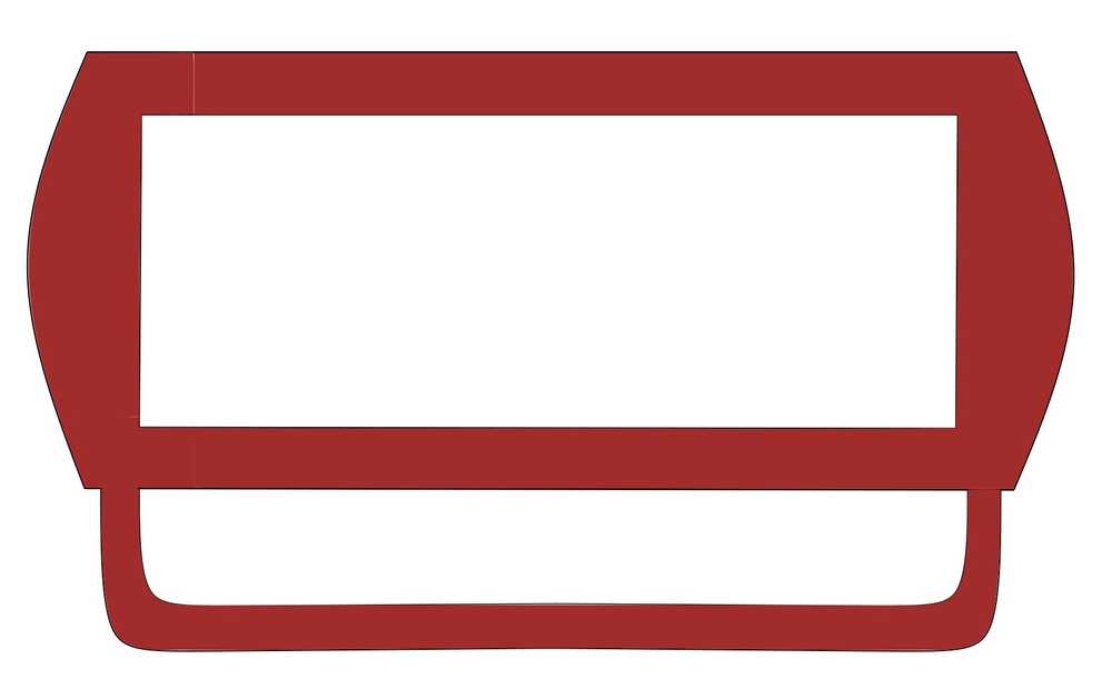
The challenge for this week was to represent a design in multiple formats. I moved to Inkscape to complete the next rendering of the hand controller:
In this representation, I removed the raised buttons. Given that a user may be using the same hand to type, it would probably be more manageable for the controls to be flush with the device.
fusion 360.
model pass [2] + basic simulation.
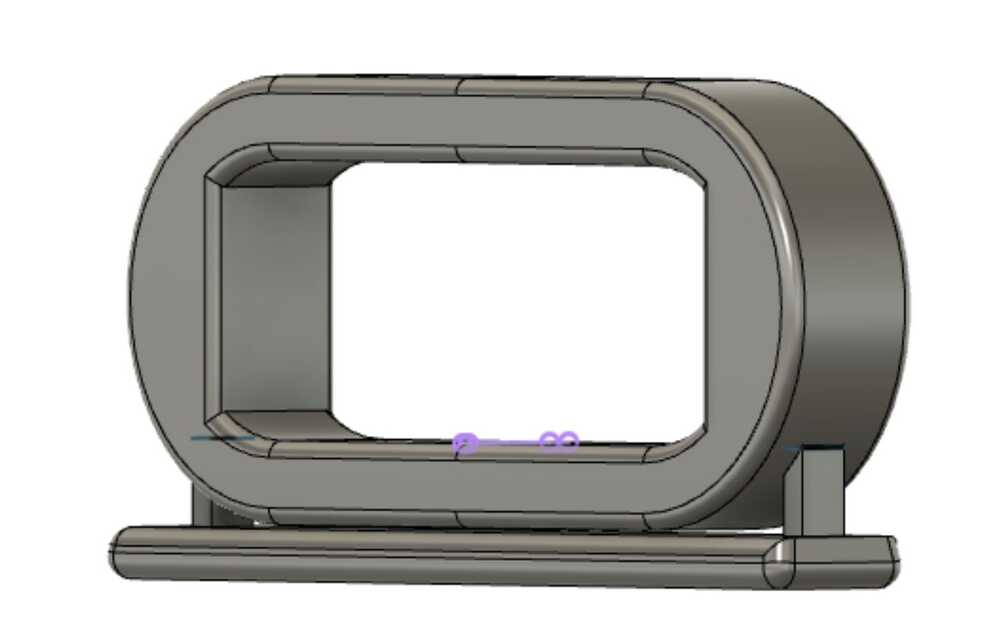
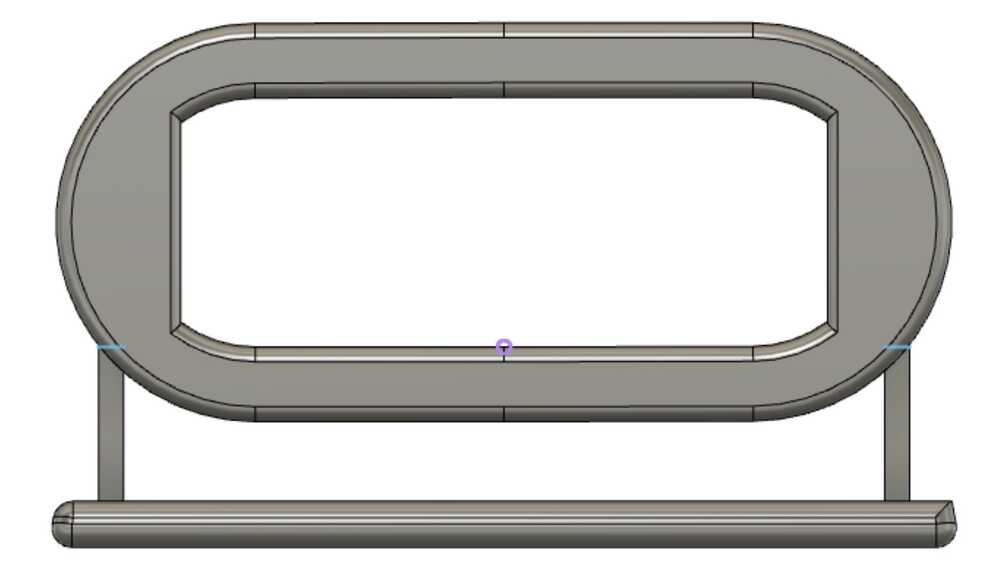
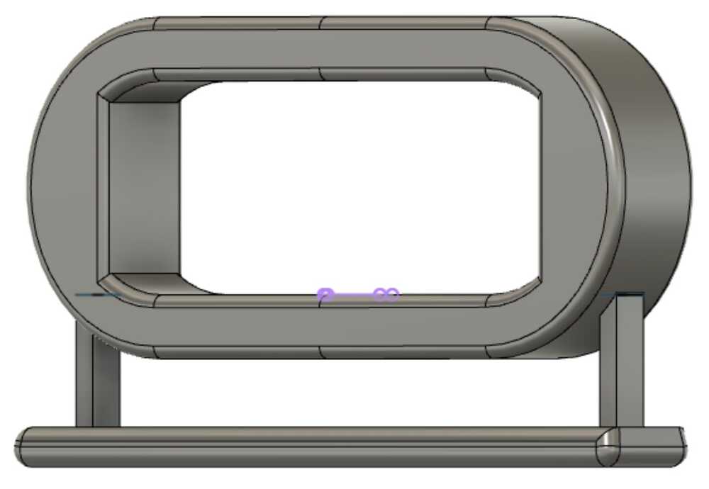
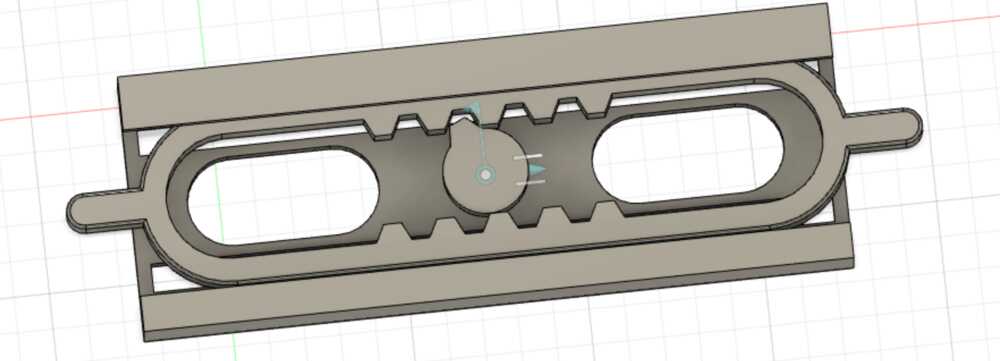
The last model representation was done in Fusion 360. Using circle and fillet commands, I tried to veer away from sharp edges. Also, like the vector representation, this model does not feature protruding buttons. The press control mesh was used to subtract insertion channels into the base of the device and the Fusion animation feature was used to represent the in-out movement of the push controls. The 3D model and push control and different states of compression are illustrated in the above images.
Final project notes:
I spoke with Neil and the course staff about my idea and received multiple suggestions:
1. Rather than use MIDI control, consider using keyboard controls (aka) interface with your device as if it were a keyboard
2. For nested buttons + controls, there is the option of capacitive touch sensors; however, they can be difficult to rely on depending on the surface they or on/under
From these discussions, it became clear that the most unpredictable and therefore time-consuming aspect of the project would be the design/placement of the sensors to allow for unhindered hand movements. Having worked with Gibber, I knew another time draw would be getting the circuit to speak to the live coding environment without overloading or crashing it. Gibber is not a commercial coding environment and can crash from syntax errors and overloading commands so I had to make sure that the device would not result in an immediate crash of the program.
Knowing this information, I decided that my project goal was to implement a hand controller device that can [1] speak to Gibber/ type in the Gibber environment, [2] features at least 2 sensor/controls interfaces, [3] has sensor/circuit placements to allow for unhindered hand movement and easy sensor interaction. From this point, the stretch goal would be creating a housing for the circuits and/or adding more control interfaces.
[2] prototype sliding mechanism for hand controller
week 3: design, 3D print, and scan!
the design.
The assignment this week was to design and print a small 3D part that couldn't be created subtractively. To accomplish this, I decided to print 2 connected parts that would move relative to one another when printed. The idea was for this print to be the first prototype for the press control mechanism in my final project.
I'm going to test a design for that push control/grip on the bottom
My vision for this control is an in-and-out movement that translates to continuous values in a 0-1 range. On the sensor side, this would likely require a potentiometer. The potentiometer would measure the angle of some spinning/moving part, which means translational motion in 1 axis for one part would have to result in rotational motion in another part. What would also be cool would be for the press control to reset itself when released-- this would likely mean using a spring to push it back out after being pressed. A spring would also add resistance proportional to high values in the 0-1 range which could help the user intuitively approximate what value they are outputting without a numerical interface. I'll address these ideas later in the design process... for this week we are sticking to the 3D printing assignment!
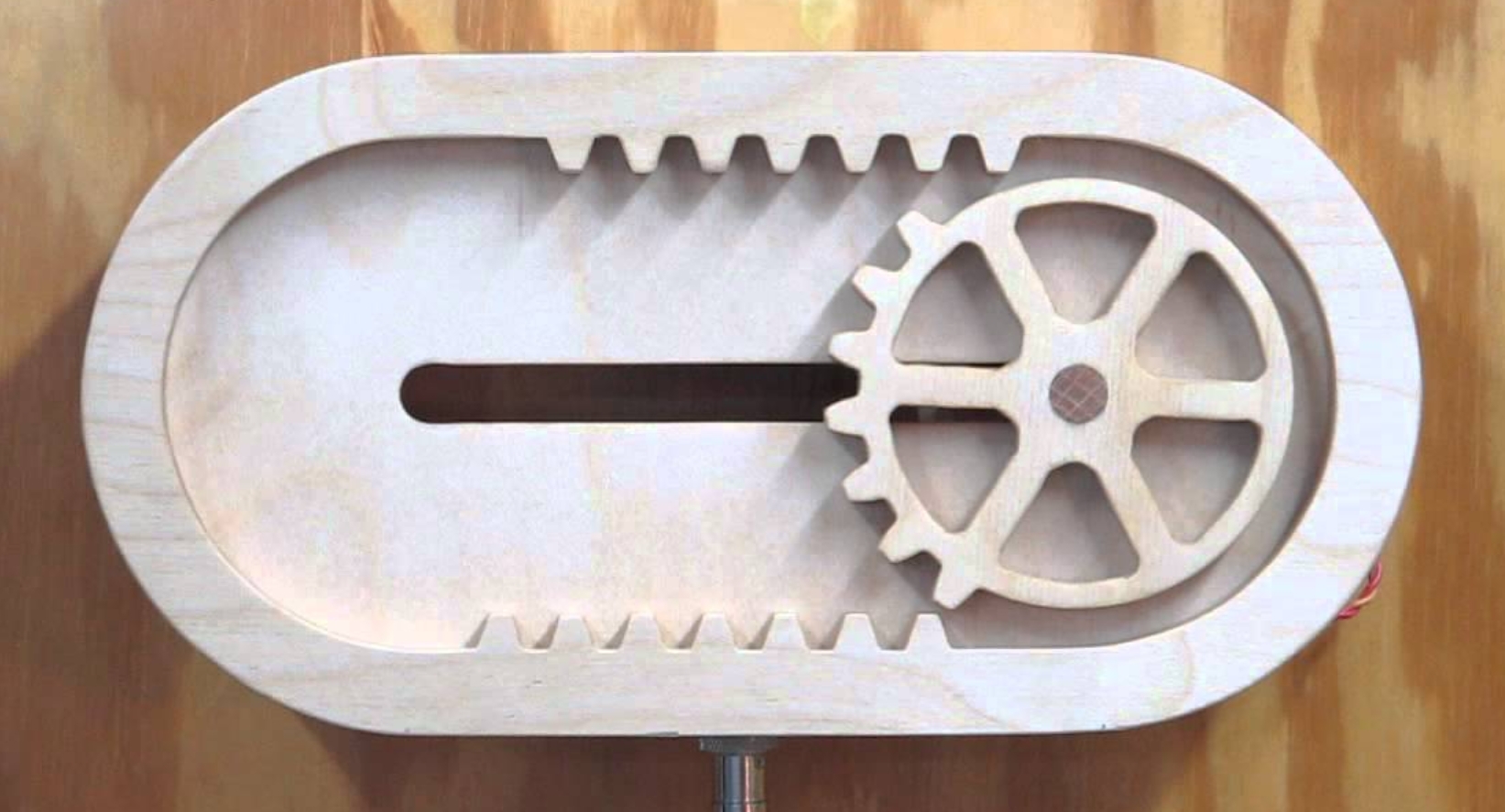
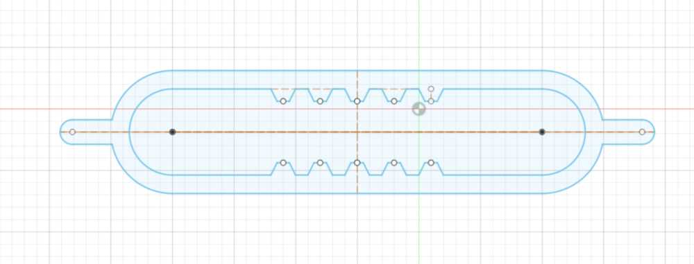
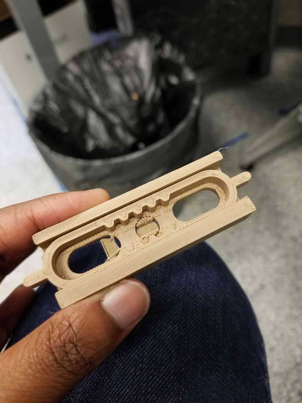
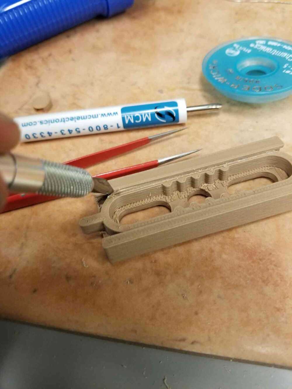
I began looking for some example mechanisms that translated single-axis movement to rotation and ran into the reciprocating gear (shown in the picture above). By holding the gear in place and moving the outside piece back and forth, 360-degree motion should be able to be achieved in the gear. Since most of the potentiometers I have used do not have 360 degree rotation, the gear design, and whether it will turn 360 degrees or less will be left to later weeks when the design requirements become more clear.
The process of designing the two parts
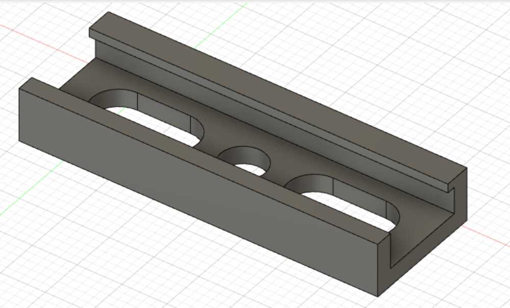
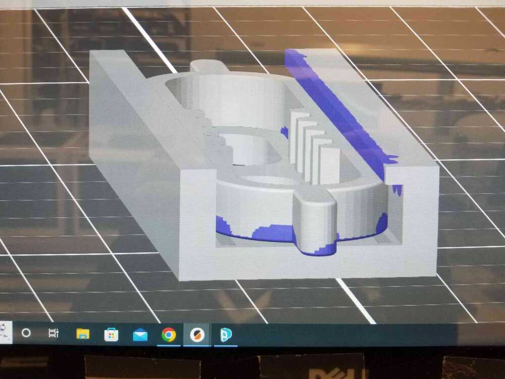
I designed the slider (the part with the teeth that interlock with the gear) inside of a single-axis channel so it could be slid back and forth on a single axis. I left a hole for the gear and removed some additional areas from the channel in order to decrease print time. I also removed areas near the edge of the channel in order to create space for supports that would lift the slider piece inside the channel so it would not stick to the channel itself during printing. I gave the slider about 0.5 mm or less of wiggle room inside of the channel to account for material expansion/shrinking and to allow for supports to be printed between the parts. I also placed an overhang in the channel on one side to determine whether it would be necessary to allow the slider freedom to be popped out in order to remove supports.
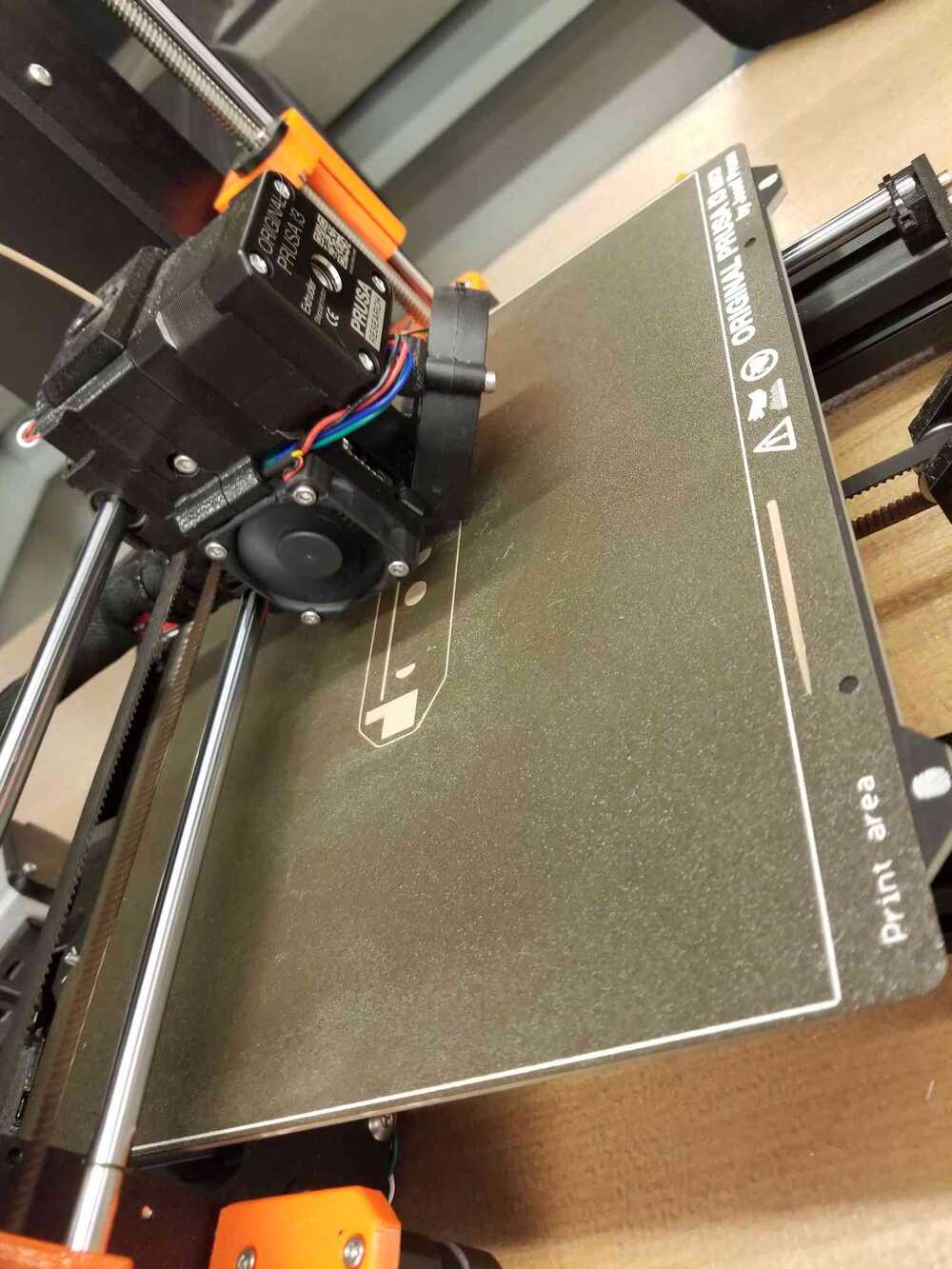
Because of the nature of my part, it was recommended I use dissolvable supports so I wouldn't have support residue left back on my part that could impede motion. Unfortunately, a printer with dissolvable supports was not available to me during my lab time so I took tried using the Prusa 3D printer. When setting up the print, I decided to paint on supports since the generated supports were tying the slider and channel together at too many places. I placed supports in the openings in the bottom of the channel, 1 layer of supports between the lever and channel, and supports under the overhang (even though the overhang was small enough to maintain its structure, the proximity to the slider likely would have caused it to stick).
group assignment
I based my printing assumptions on the design rule prints my group printed out to see what angle/overhang length would lead to stringy plastic.
the 3D printer
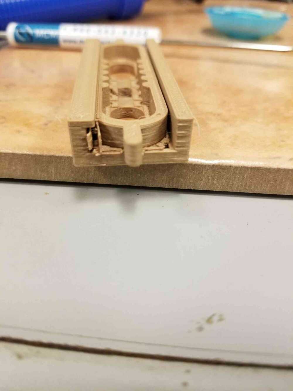
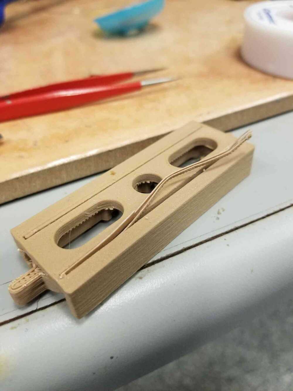
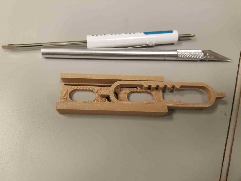
My print time was about 38 minutes. I took off all the outside support by hand and had to take an Exacto knife, screwdriver head, and tweezers to the overhang supports and supports embedded in the base of the channel. After some pulling and scraping, I got my part!
I did end up having to twist the slider slightly in order to separate it from the support between it and the channel, taking advantage of the fact that the slider was held in place by an overhang on one side. However, it was cool to see that the artifacts left behind by the support between the slider and channel prevented the slider from sliding out due to gravity-- it held the slider in place. When I get closer to defining design specifications for my final project, I will consider whether having this support layer for resistance or switching to dissolvable supports for a smooth print would be optimal.
[3] completing my first project objective: augmenting Gibber code environment using printed board
week 6: program a board!
week 4, part 2.
it's time to live code ;)
This week, I plan to use the board I made from week 4 to test the HID library. HID stands for Human Interface Device. It is a library that turns your circuit into a controller-- like a keyboard and/or mouse. I want my final project device to interact with the code box on Gibber, an online musical live coding environment. I plan to use the buttons on the week 4 circuit board to do some basic testing, just to see what is actually possible with the library.
I programmed the board using the TA tutorial from this site and my programmer board, before it broke.
When I first tried uploading a test program, the Arduino IDE terminated the process, saying that I had to declare the type of device the output board was becoming. In the error notes it said that I could, for example, open Tools -> USB Config and set the USB Config value to HID_ONLY.
I tried this basic program first:
This program just prints "Hello World" to wherever the cursor is. In the video I have Notepad open and every time the board prints "Hello World" at the cursor location I press enter. I tested the program in the Gibber environment and its non-stop printing caused Chrome to crash multiple times. I went back to change the delay between printing and/or tie printing to button presses to stop this from happening and realized that the Arduino IDE was unable to recognize my board as a writeable device.
I realized that this was probably because I had set the USB Config value to HID_ONLY... I should have read into that more.
I later realized that I could reset the board by repeatedly pressing the reset button.
I was kind of surprised that worked at all but I'll take it.
After reading through the USB Config options, I set it to CDC_HID so the board could be an HID device while also being writeable via the Arduino IDE.
I wrote some additional functions in my test code while thinking about how my device should interact with the code box. The code is just a controller and can not read the Gibber code box, so I probably would not be able to do positioning based on finding keywords already in the code box. The order of Gibber code on the page does not matter. What does matter is the order of code execution. This meant that as long as I could find a blank line, I could use my device to paste and execute code. The user would just have to be somewhat vigilant-- making sure that variables used by the device have already been declared/previously. Regardless, Gibber does its best to ignore code errors, letting you know something is wrong in the site inspect panel. With these ideas in mind, I test the board in the Gibber environment, trying to simulate how the device might change the code box during a live-coding session:
I have the program using the page down command to jump to the bottom of the page, the enter command to create a new line, and the home command to jump to the start of the line in case the cursor isn't there already. These commands ensure that the cursor is now at a blank line no matter what is on the page, or where the cursor was when the command was executed. I have the program paste "Hello World" so I can see its location. In the video, you can see how I marked a section at the bottom for the device code. I felt that having the device interact with code the user has written would be confusing, and error-prone given that a user that is actively live coding could change these lines around and/or delete them completely. I imagine that in an actual live coding scenario, it would be most convenient for all the variable definitions and user code would be at the top while all of the modification code (ex. chord changes, filter changes) from the device would be at the bottom. In the future, it will be worth testing having the device print lines at the top of the page rather than the bottom, in case the device wants to edit a line it has already printed. If it prints at the top of the page, these lines would always be in the same place, not being moved down by each additional line of code. My only worry here would be that there would possibly be execution order issues. For example, if Gibber crashes (which it does), usually you just re-execute the entire page. If all the modification code is at the top, before the variable declaration code, nothing will execute. Conversely, if we keep the modification code at the bottom, we can add code that keeps track of what was printed where in relation to the bottom of the page.
Now to test the above ideas on a page with actively running live code. I opened one of the tutorial samples and executed the Gibber code in the sample. I also added new functions to my device code. Before, I just pasted "Hello World" into the code box, but now it is time to paste real Gibber code and to also execute it (using ctrl-enter). I decided to run a test where the board would change the reference scale degree of the running sound when either button is pressed. I kept the function that brings the cursor to the bottom of the screen, but this time it prints a redefinition statement for Gibber's Theory library: Theory.degree = 'ii'. The roman numerals in this statement define which scale degree above the root note should become the new reference note, while remaining in the original key. Doing this multiple times creates a chord progression.
In the video, upon pressing the button tied to pin 6, I have the program jump to the bottom and paste Theory.degree = 'ii'. To demonstrate what replacing a line might look like, given the correct placement of the cursor, I press the button connected to pin 7 select the line, delete it, and then print Theory.degree = 'iv'. You can hear how the chord changes in the video! Note that Gibber does not execute changes immediately. It waits for the current 4-beat loop to finish and then executes on beat 1 of the next loop.
These tests give me a lot of hope for the functionality of the final device! For the coming weeks, I will look into designing natural sensor interfaces that will aid live coders during their performances!
[4] prototyping sensors for the hand controller
week 8 - 9: input + output devices!
new final project ideas.
what about tuning?
In lecture, Neil showed us some options we had for choosing input and output sensors. I was intrigued by the vibration sensor, since it seemed a lot like contact mic (a mic that picks up the vibration frequency of the surface it is attached to). I am always looking for cool easy-to-use features to add to my final project, and seeing this sensor gave me an idea:
what if I could use a contact mic/vibration sensor to pitch match while live coding?
The way I imagine this working would be that the vibration sensor would be attached somewhere to the outside of the hand controller, and when trying to change the pitch, the user would hold the mic up to their neck and hum the desired note.
In my own experience, live coding functions often result in pitches that are detuned. When these pitches are detuned, it is difficult for me to guess their frequency and/or relative pitch because they are somewhere in-between the Western standard spacing of pitches.
I'm not sure how feasible this is, but I think it's probably worth a shot?
microphones and speakers
amp it up.
My idea for this week is to use a contact mic/vibration sensor to pick up an intended frequency from a hum. This will go through the microprocessor, where the frequency will be isolated/ identified. The program will then take its guess and generate the frequency as a pure tone through an output-- a speaker.
The main issues with microphones and speakers that are connected to microprocessors are insufficient voltage and current. For instance, the sensor microphones generate a voltage/wave that the microprocessor reads; however, on it's own, the microphone generally produces such a small wave that the microprocessor misses the reading. Similarly, the microprocessor can't put out sufficient current to drive a speaker at a hearable volume. So, some sort of amplification both ways is required.
[week 8] let's start with the input.
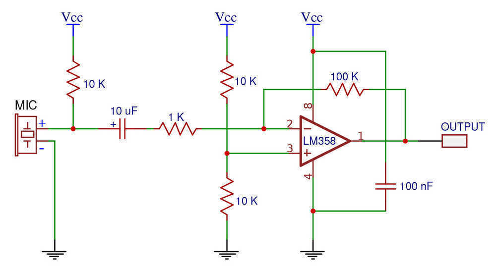
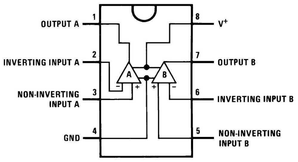
For the mic input, I want a voltage/wave amplification, but not a ton of current amplification since it is going into the microcontroller. I chose the familiar LM358 op-amp to accomplish this. The amplifier circuit is common so I found an example online:
Since the output was going into an analog port on the SAMD21, I wanted to make sure that the input would not recieve higher voltage than the reference analog voltage 3.3V. To do this, I set the positive rail of the LM358 to 3.3V. The downside to this is that you generally do not hit the rail voltage of an op amp, so my voltage measuring range would be compressed.
After programming my breakout board, I got a breadboard and some wires to create my circuit. Almost immediately, I realized that I should have created a ground pin when designing my board. The only pin outs were the digital and analog ports. To create a common ground, I had to set one of the digital ports to low and then wire that into the ground rail of the breadboard. It works, but took more time than it needed :/ .
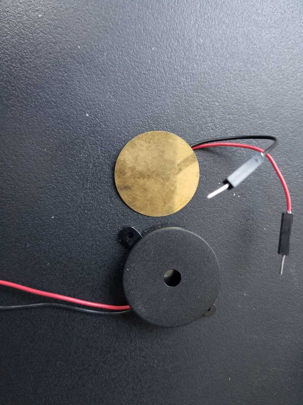
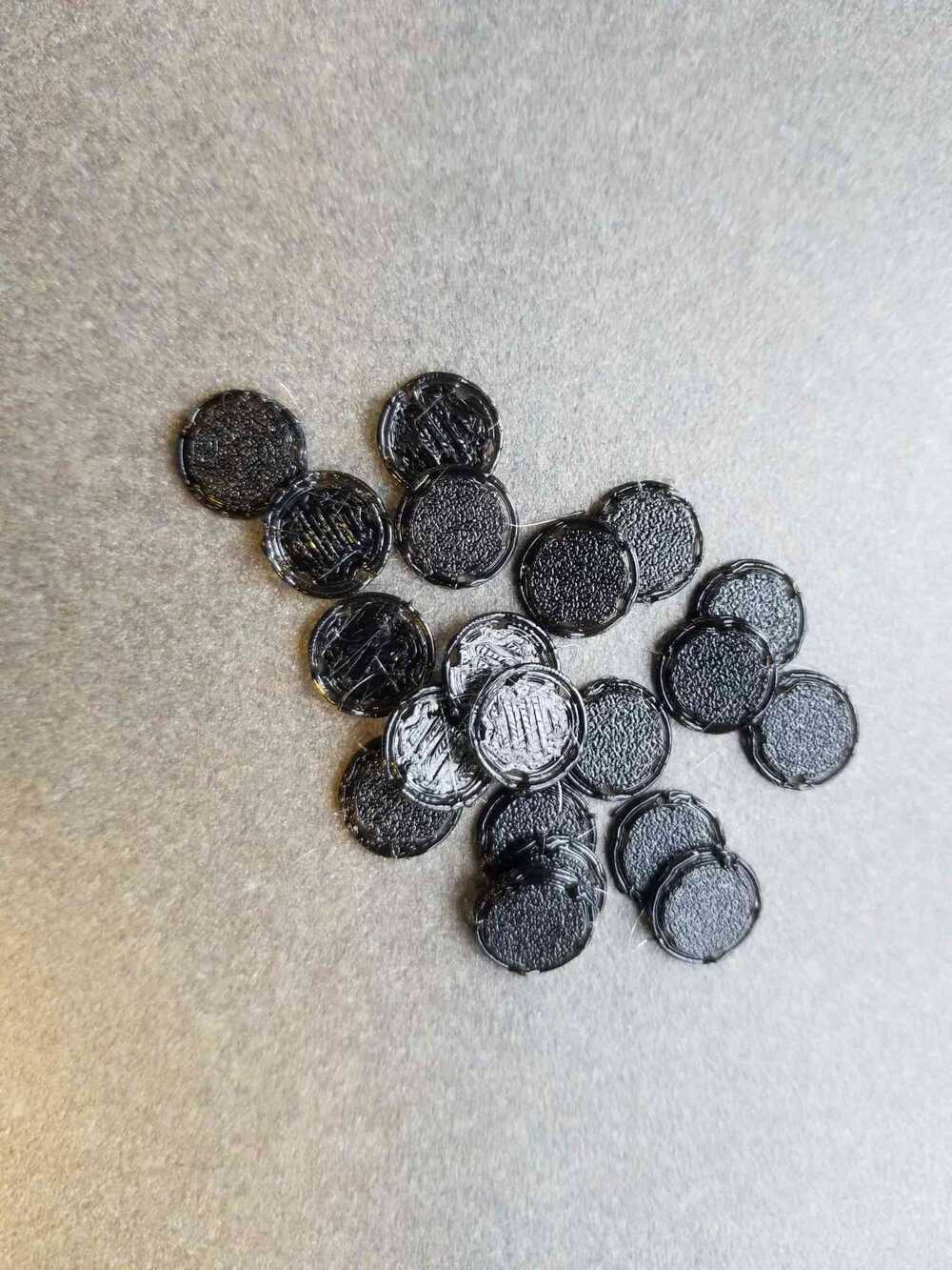
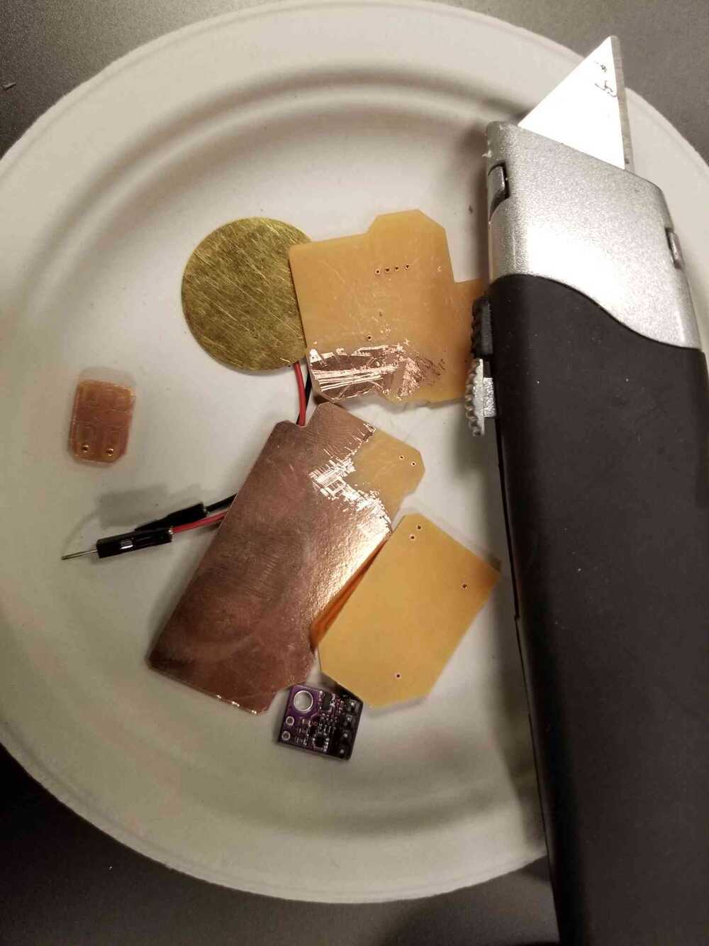
I keep a lot of my old sensors so I had a couple mic options:
The gold sensor is a contact mic and the black sensor is a vibration sensor. These sensors function similarly: they translate vibrations they experience into voltage. I got the vibration sensor from the lab. Though the vibration sensor looks leagues better than the contact mic in terms of quality, I had a feeling (given my experience with contact mics used in live electronic music performance) that the contact was worth testing as a viable means of relaying the frequency of a surface it touches.
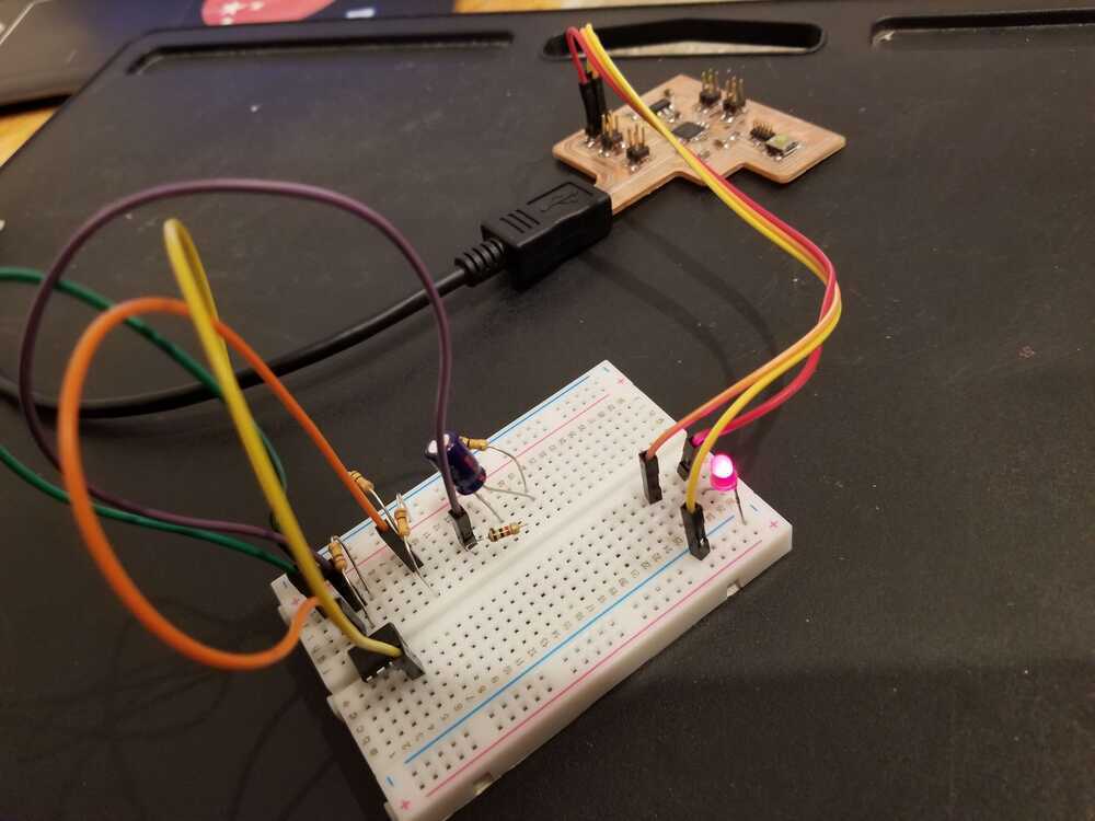
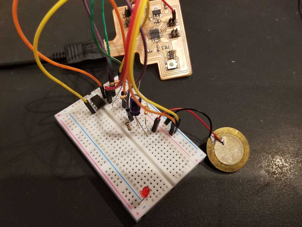
I set up the circuit with the contact mic first. I was debugging as I went using an led I had placed on the board. There are many pins coming out of the SAMD21, so after choosing a pin, I would generally test to see if my wire placement was correct by setting the pin high and sending it through an LED to see if it lit up. I repeated this process to check all of my input pins and then completed my microphone circuit:
** side note: PLEASE ignore how horrible the wiring is. I was away from the lab and (though it pained me) they were the only things I had on hand.
I created a basic program where I read the input values from the microphone and outputted them to the Arduino Serial Plotter. I held each mic to my throat and hummed a pitch. I took video of the responses:
This is the contact mic. You can see clear differences between when I am humming and when I am not. However, there is still a fair bit of noise.
This is the vibration sensor. Like the contact mic, you can see clear differences between humming and silence. There is a lot less noise here too.
The vibration sensor seems to be the pick here. Regardless, I think I will keep the contact mic an option as I move to augment my testing apparatus to include output sources.
The next steps for testing the input would be trying to sample the frequency from the mic inputs. While there are likely libraries available that will do frequency identification for you, I feel that it may be necessary to make a custom system. The way I imagine things is that the user will press a button, hum a sound, and then release the button. This will give the arduino a timeslot in which to take samples. Based on the readings, sampling rate, and the time period in which readings were taken, you can calculate frequency. This is the basic solution. If necessary, I see myself exploring fourier transform algorithms. The frequency on the surface of the throat is not a pure tone, so various other frequencies will be mixed in with the target frequency-- this where I see the fourier transform coming in.
I leave the investigation of these options to future weeks since this apparatus could be important for my final project.
[week 9] let's add an output.
While I don't think output devices will be featured in my final project, I recognize their utility for debugging. I had two ideas this week for helpful outputs: an OLED and a speaker. So far, I have only been using Serial Plotter on Arduino for visualizing outputs. It is hard to look at other variables while also monitoring the Serial Plotter, especially when printing to the Serial causes it to scroll up very fast and makes it difficult to hang on to important values while seeing live outputs. Having an OLED would help with data visualization. Additionally, given that the output of my code will be the guess the circuit has for the frequency I hummed, it would be most helpful if I could hear the guessed frequency, rather than read its numerical value. That way, I could determine how correct the guess is using my ear while humming the correct pitch.
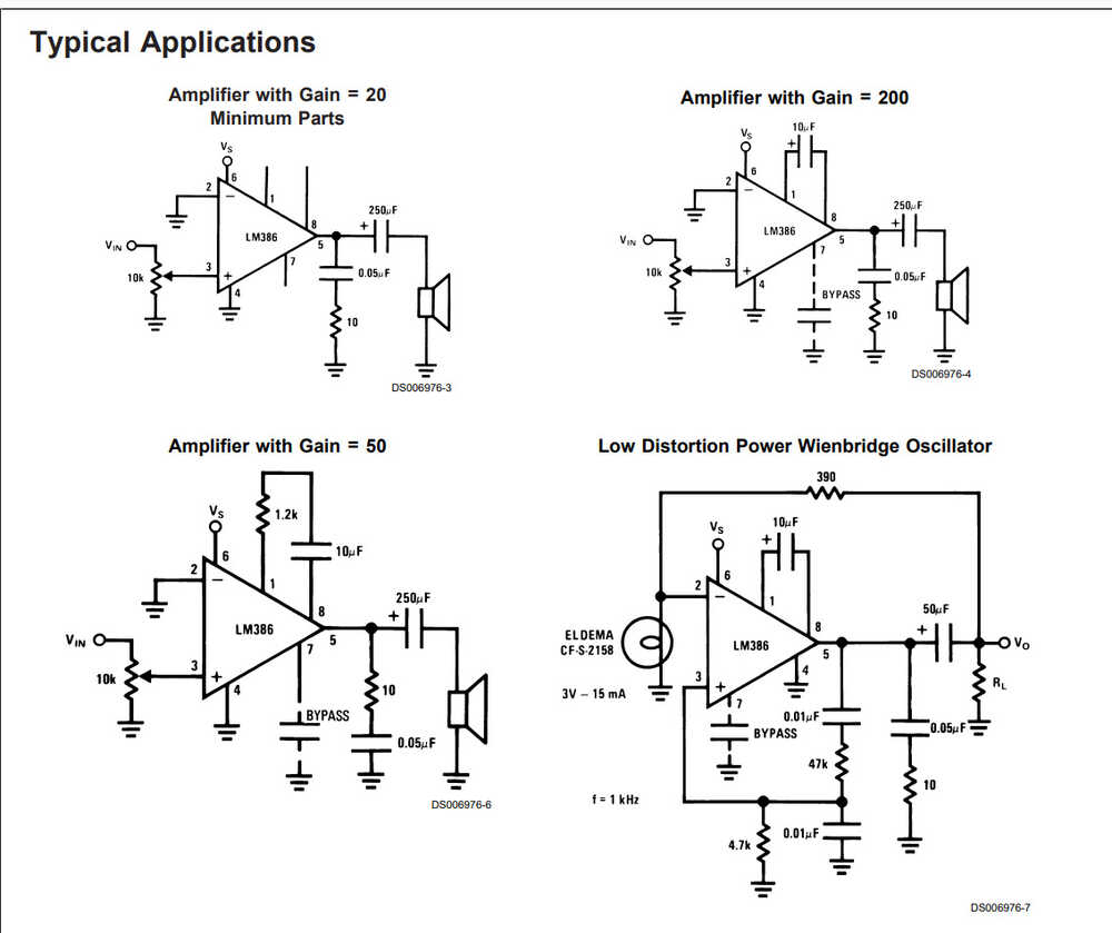
I wanted to do the speaker first, given that it was probably going to be the more useful of the two. For the speaker, I wanted voltage AND current amplification so I used an audio amplifier (LM386). The datasheet for the amplifier lists example circuits:
The amplifiers will only boost within the voltage rails they are given. I got a dc jack and a 12V power brick to power the amplifier (exciting!). I collected the circuit components, but later realized that I had collected the components for a different amplifier. Unfortunately for me, I realized this fact when I was working at home, without lab supplies. Guess I am saving the speaker for a later week :(
Thank God for back up plans -- it was time to hook up an OLED screen. Luckily, that was something I did have at home-- again, never throw anything away.
Let's try this again.
[week 9] let's pretend the OLED screen was the original plan :)
I thought the OLED screen would be an easy wire-up.
I was wrong.
The first issue that came up was that the OLED screen required 5V to run. I had no pins for GND and 3.3V, so I definitely did not have one for 5V. I will have to include that on my next breakout board. Luckily, I have like 7 Arduino boards lying around in my house. Those boards have 5V pins :). In addition to my ugly wiring, I now had an entire Arduino connected to my circuit. It was not optimal, but it worked.
There is a library that is available for OLED screens that is commonly used when hooking the screen up to an Arduino. It references the SDA/SCL ports that are labeled on the Arduino. Rather than let you decide on which ports are SDA/SCL for general boards, the library (outside of the main file) defines them for you based on your board type. You also can't change these presets. Great.
Looking online, I learned about the TwoWire library which directly addressed this problem. After replacing the initializers in the example file for the OLED screen, I was able to get some outputs.
That is all for these weeks assignments. In future weeks, I will move to implement the frequency finding code + speaker circuit!
[5] completing my second project objective: more work on the sensors
Pitch Matching with the Contact Mic
Continuing with the work from weeks 9 and 8, I moved to write a program that would allow pitch matching with the contact mic. The idea is that a user would hold the mic up to their neck (or just around their face near their mouth) and hum a note. The vibration of the throat would vibrate the mic and that vibration would be read into the program.
I hooked up the mic on my debugging breadboard in week 8/9 so I focused mainly on software here. With a frequency coming in I knew I could use the Fourier transform (FFT) algorithm to extract the most prevalent numerical frequencies from the contact mic's outputs. The FFT algorithm is a solved problem and is widely implemented, so I found an implementation of the code online.
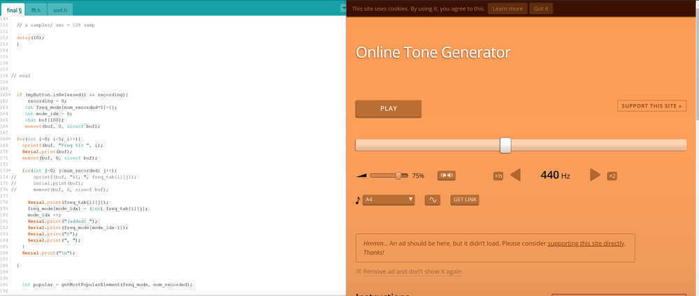
To make the code/circuit work for this use case, I added a button for the user to press while humming, so the FFT function would be able to know what to sample, and how long to sample for. As long as the button was held down, the function would be called repeatedly, arrays of 128 samples sent to the FFT function over and over again. When the button is lifted, the FFT function outputs the most popular 5 frequencies it detects. I used a pitch generation website to check how accurate the pitch matching was:
It was surprisingly accurate! However, the FFT function outputs the top 5 most popular frequencies. So while the correct frequency was among the outputs, the program had no way of knowing which one was the correct one.
To solve this problem, I created new arrays to collect the outputs of the FFT function over the course of the button press. At the end of the button press, the collected frequencies would be sorted and then checked for the most popular frequency. Even though the timbre of humming comes with its own series of unique frequencies, I expected that since the desired frequency is actually being hummed/ within the range of the human speaking range, it would be the most prevalent frequency, appearing somewhere in the top 5 frequencies of each FFT call. This allowed the program to output the actual frequency after each button press + record! With this, I complete my "at least 2 sensor interfaces" objective for my project.
Capacitve Sensing for Button Presses
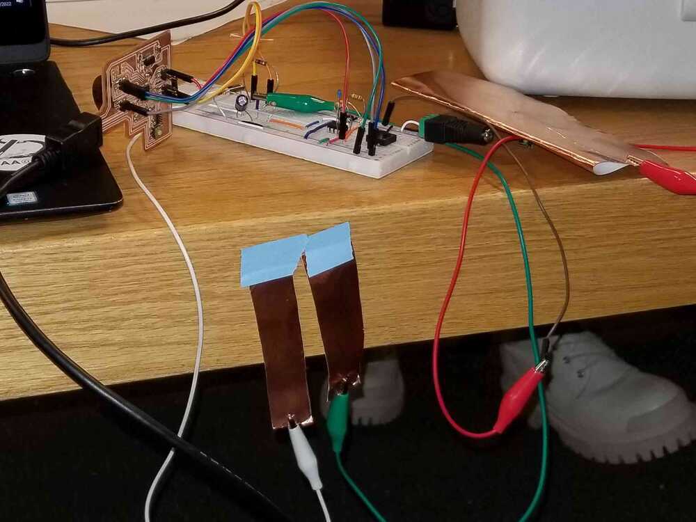
When I first pitched the project, it was recommended that I use capacitive sensing for the buttons on my device. I decided to test them out:
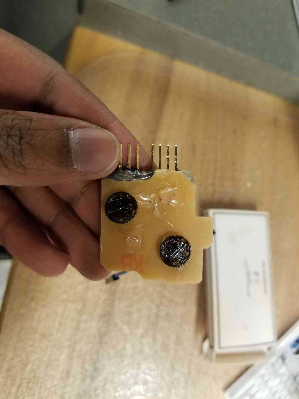
The two strips of copper are the capacitive sensing interface. One is charged and the other charges when a finger comes close. The first strip creates a capacitor with your hand and starts charging your finger. Your finger, in turn, begins charging the other strip. Depending on how fast that strip charges and discharges, one can determine how close a finger is. I added a 10 MOhm resistor between the 2 to get a larger response.
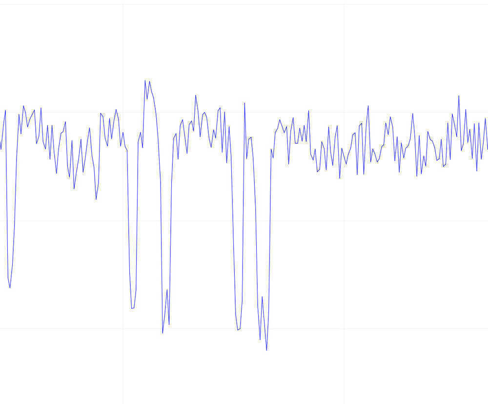
In the image above, I press directly on the sensing copper strip. The response is clear. In the second half, I placed a piece of cloth over the sensors and tried again. Just with this much of a disturbance, the response was totally different. I expected as much with such small copper sheets and low voltage. I determined that the capacitive touch sensors were probably not a good fit for the device, especially since accurate button presses was essential to its functionality. I decided to move forward with physical buttons.
some additional ideas!
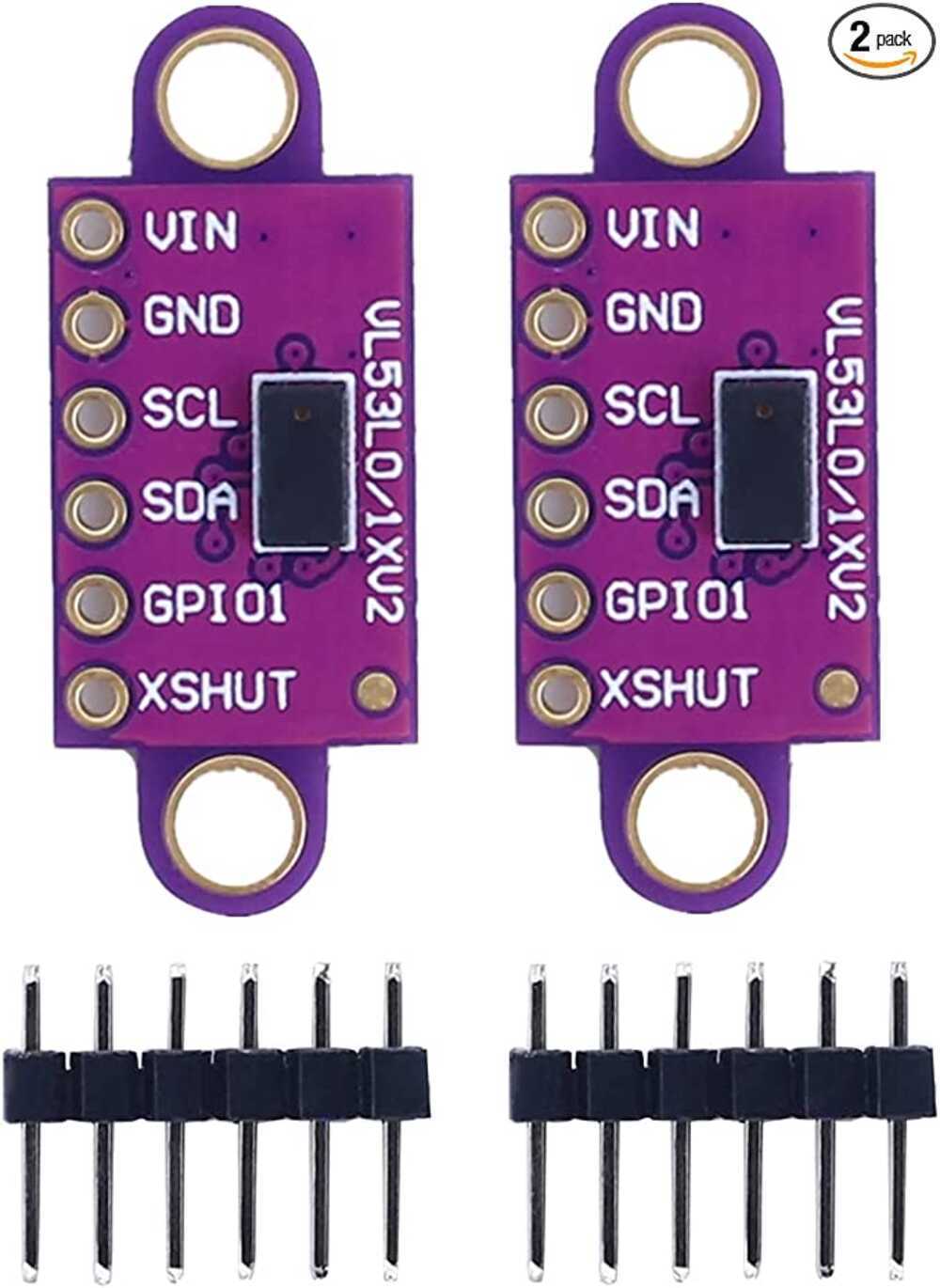
Time of Flight Laser Sensor for Filter/Volume Control?
I had a couple more ideas for sensors that I wanted to try before moving on, one of which was the distance sensor. The idea for this sensor was that it would be on the underside of one hand and the user would hold up their other hand and measure distances between their palms. These distances would be mapped to a 0-1 range in software so the user would be able to change range controls such as volume or filter strength.
I had many problems getting the sensor to run. Much of the issues stemmed from the fact that the SDA and SCL pins are sometimes tied directly to the Arduino pin locations and therefore, are sometimes not able to be found. The SAMD21 has multiple SDA/SCL locations, but even when using the setting that allowed programs to search for SDA/SCL hardware locations outside of the default, the sensor would not initialize. After manually defining the SCL/SDA locations, and exchanging the Wire library, I was able to get it to work. It was very accurate-- I'm definitely getting some of these for personal use.
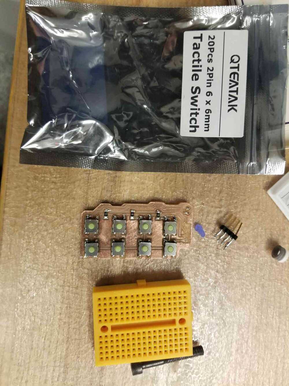
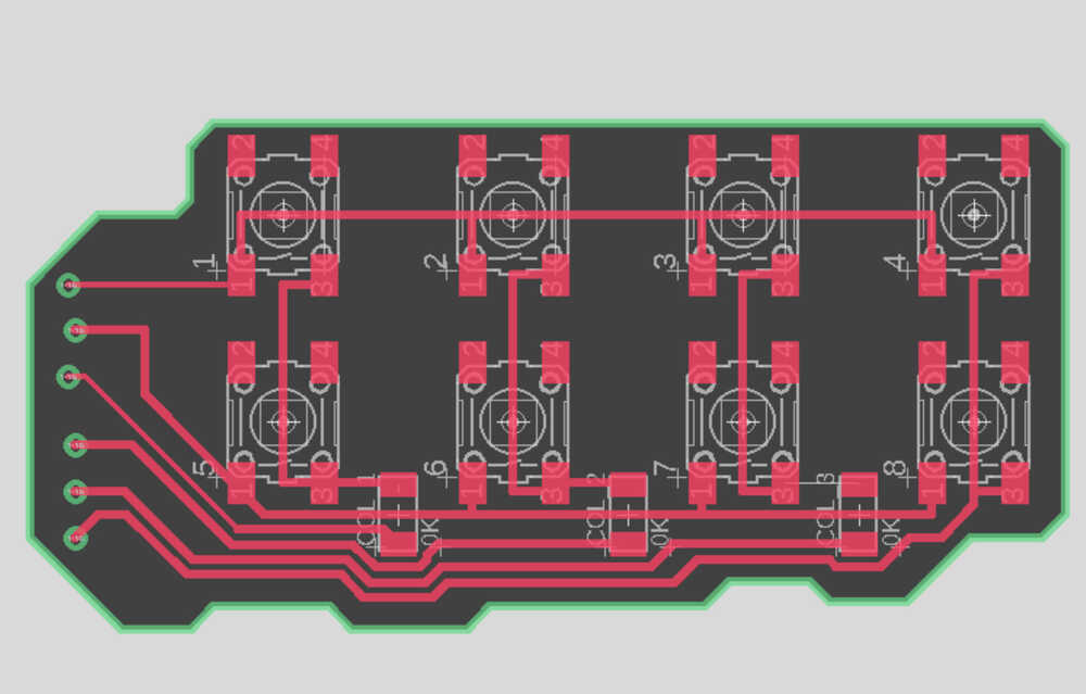
Button Array Keyboard?
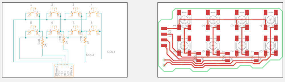
I also wanted to test out the ideas of a button array. This button array would act like a keyboard/ preset toggles to suit a user's needs. I decided to use the common matrix format commonly used for keypads. It has outputs for each row and column of a button array, using the collection of button inputs to determine which button is being pressed. I designed a board for the array and printed it in case I got to implement it.
[6] completing my third project objective: rethinking device design
Circuit Placement + Device Design
When I began designing circuits to replace my debugging breadboard I had to think about how they were going to fit on a user's hand. The original design was a sort of oval-shaped case that surrounded the hand. Thinking about this design, I found that it would probably be a hindrance for someone who is actively live coding. Bringing your hands to the keyboard would probably result in the device sliding across the keys.
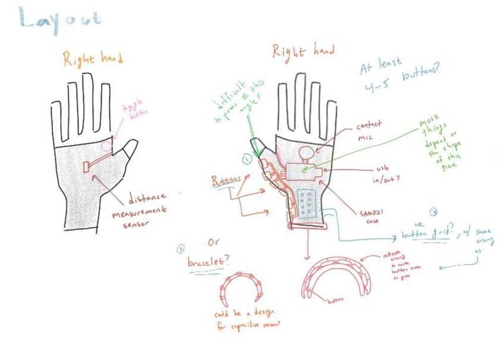
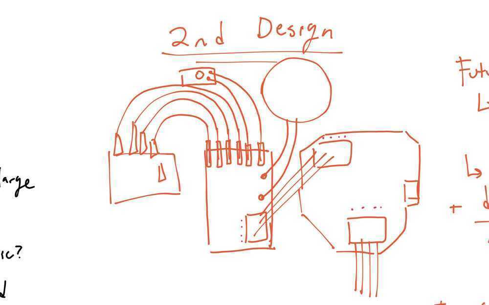
My next idea for a device design was something that was hopefully more discreet:
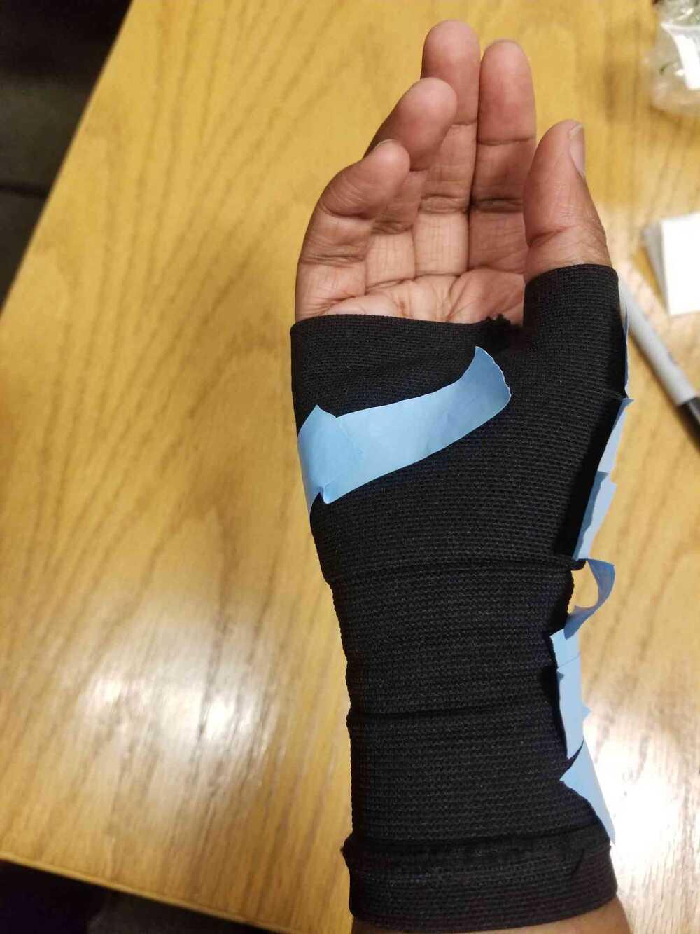
The idea is for the circuit to sit on a fingerless compression glove. The fabric glove would allow for dynamic and comfortable fitting and would be tight enough that the sensors would not slide around. I included the extra sensors I wanted to add in this design, in case I got around to them.
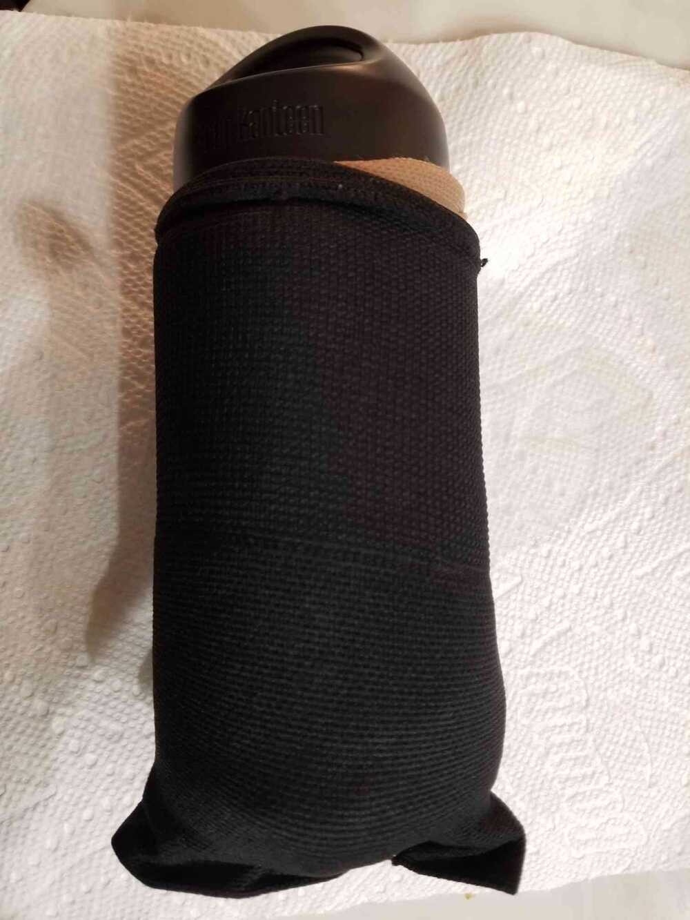
A small aside: I bought some gloves and they ended up being too small to wear comfortably. After some Google searching, I learned that you can use fabric softener and hair conditioner to stretch fabric out:
Fabric softener + conditioner solution (left) + Stretching the glove out using a water bottle (right)
The gloves smelled pretty nice after so that was cool.
Okay, back to the design:
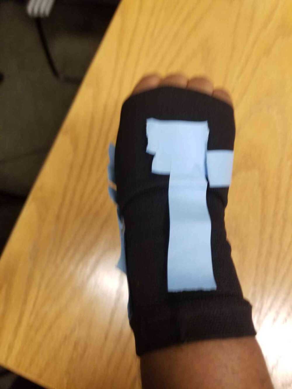
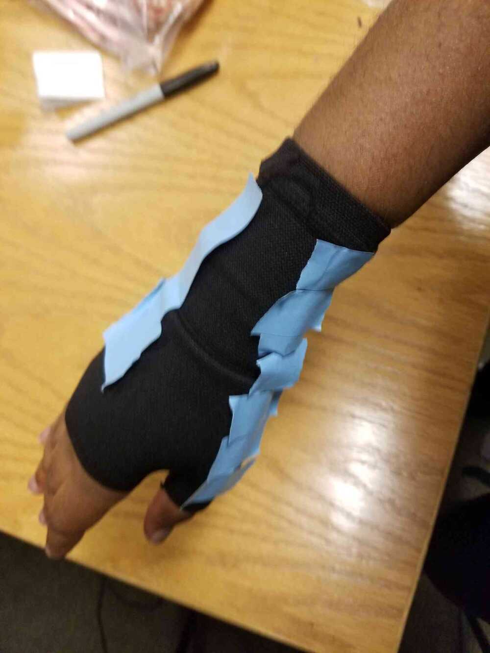
To help understand how the design would look, I tested their placements on the glove themselves:
I definitely underestimated the difficulty of determining a design that would fit on the hand. I had to account for the fact that glove would be slipped on and off and that the top of the hand is a curved surface-- making it difficult to place large circuits their. I planned to design the circuits + sensor placements as shown in the picture above to try to account for these concerns.
I placed the contact mic in a place I found that was most natural on the top of the hand to hold your hand to your neck. I placed the button used to toggle the contact mic between the thumb and first finger so it could be easily pressed using one hand. Lastly, I planned for the board holding the SAMD21 that everything is connected to to be small enough to fit on the top of the hand without too much overhang. I also included the extra sensors: the time-of-flight sensor on the palm for palm-to-palm measurement, and the button matrix on the flattest part of the hand: the wrist/arm area. I wrote down a couple ideas for the placements of the buttons: along the curve of the thumb to the wrist, as a bracelet-type shape to attach to the rist, or the regular button array. All I knew is that it would take several prints to figure out what worked best and to determine what kind of new housing would work.
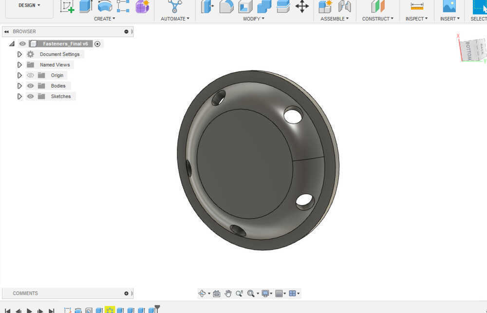
There was also the issue of mounting the boards. When thinking about housing/board mounting, I realized that simply glueing the parts to the hands would probably not work, since hands are not perfectly flat. Glueing any part that has some over hang would cause the fabric to strerch unnaturally. I designed some mounts to attach to any circuts/housing that I create:
Inspired by the shape of buttons, these fasteners are meant to sit around the middle of the underneath of glove attachments. The holes are for sewing the fastener down. It was more difficult that expected to design these parts. First, fusion's support for creating patterns on curved surfaces basically does not exist so I had to take a sort of round-about method of using the hole tool and the pattern tool together. When it came to printing, I had to find a way to print these parts to be very small, but also not break easily. I learned that 3D printers can print flexible materials. We had the Prusa printer in the lab hooked up to flexible filament so I decided to print the buttons with that printer. The material would be flexible and therefore would not break easily under the condtions it would be in.
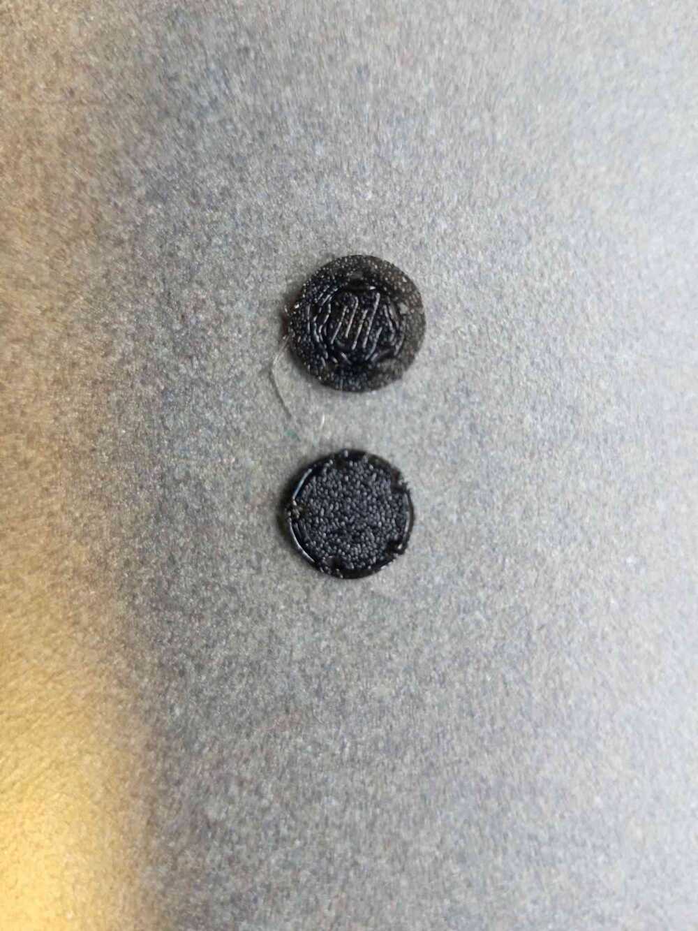
I had to print a couple of times because I knew I couldn't really use supports with the flexible material with how small the prints were. I tested the prints, orienting the caps cupside up and down and got these results:
The above print is rim side down and the below print is rim side up. The rim side up print barely has a rim, it seems like it collapsed on itself while printing. After some iterations, I went forward and printed all of the fasteners rim side down:
Problems, problems, and more problems
I've literally never spent this many consecutive hours soldering in my life
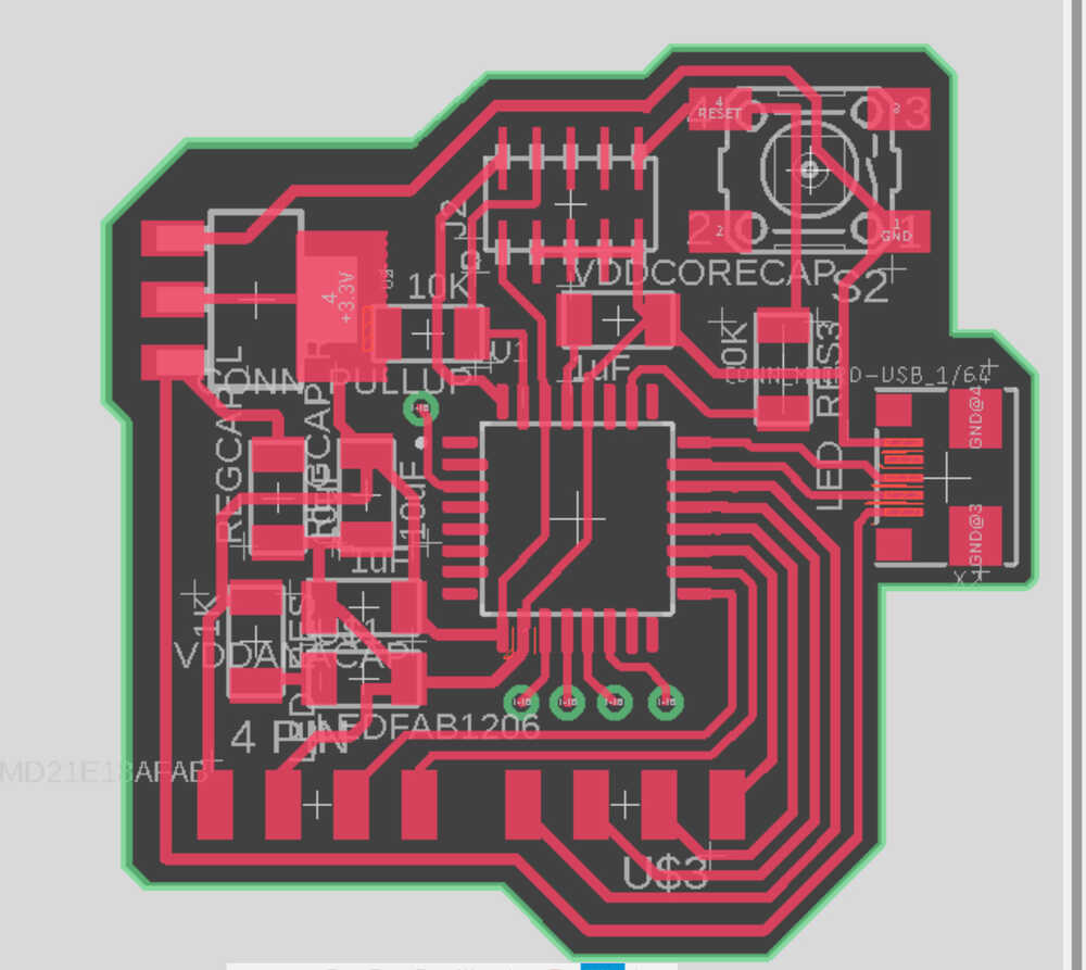
I did what I could to take into account as many of the realizations I came to while testing the design with the glove. One of the biggest design decisions I made was to use ribbon connector cables between boards. The online issue was that the ribbon connector cables had an interface of 2 rows of stacked female pins. There were no 2 row connectors available in the lab. I had to get creative if I wanted to avoid messy wiring and to allow for the creation of a housing. I got the single 4 pin connectors and then added 4 vias to each board. These vias would connect to the pins on the second row of the ribbon connector and would require stripped wires to connect to the cable. In addition, I also decided to use a micro-usb connector to lessen the power footprint on the face of the device. I also made sure that the usb faced to the right side of the hand so it would not get in the way of typing.
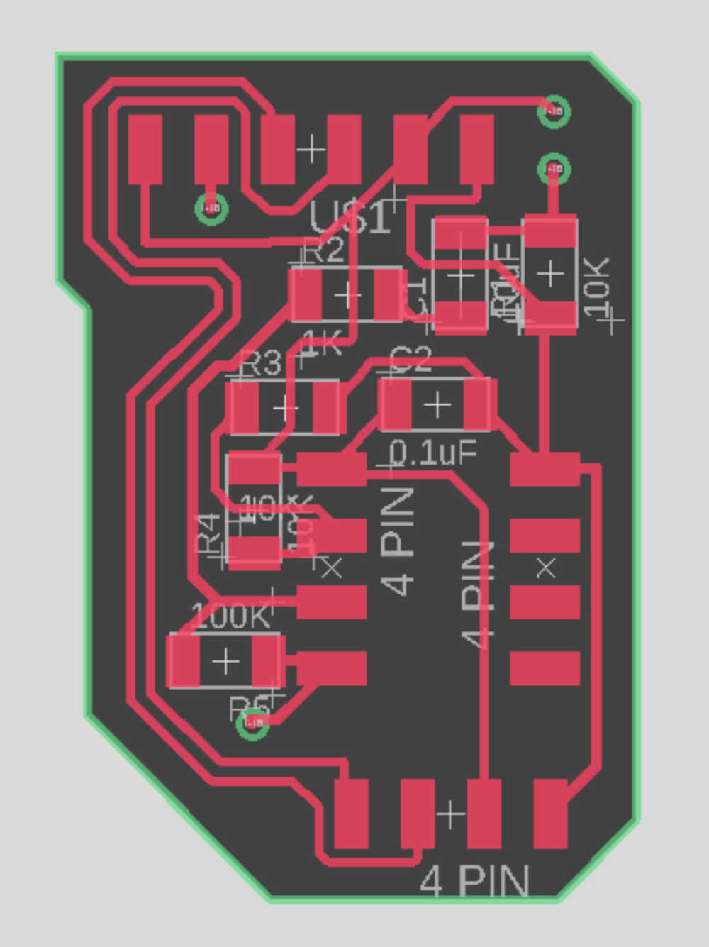
Also, while designing the SAMD21 board, I determined that adding the contact mic circuit to the board would make it either too tall or too wide to properly fit on the top of the hand without significant overhang. I decided to split the boards up. The second board would hold the contact mic circuit and that it would hold the connectors for the toggle button between the thumb and first finger as well as the time of flight sensor:
Hookup design (top left), contact mic board (top right), button array board (bottom left), and toggle button board (bottom right)
The small size of all these circuits made them all particularly difficult to solder. I spent a considerable amount of time on each of these boards.
I printed the boards and ran into some trouble. I printed on a board that was already sitting on the Othermill bed and it turned out to be double sided copper. This was bad because of all of the wire vias I had on everything. With much effort, I managed to scrape off the copper where the vias were:
I connected the fasteners and sewed the boards to the glove the way I designed it-- everything fit (last objective complete)!
Here are where the problems began. While putting everything together, the connector snapped off of the button matrix when I acidentally knocked it off the table:
I was ready to replace it with a breadboard and switches, but the usb micro connector snapped off the SAMD21 board in a similar manner. The nature of the device + the glove made it difficult to ensure the integrity of the circuits. I promptly replaced any connectors I could to via connections and I added a male USB end to the SAMD21 board to prevent anymore surprises. Time for more soldering :/
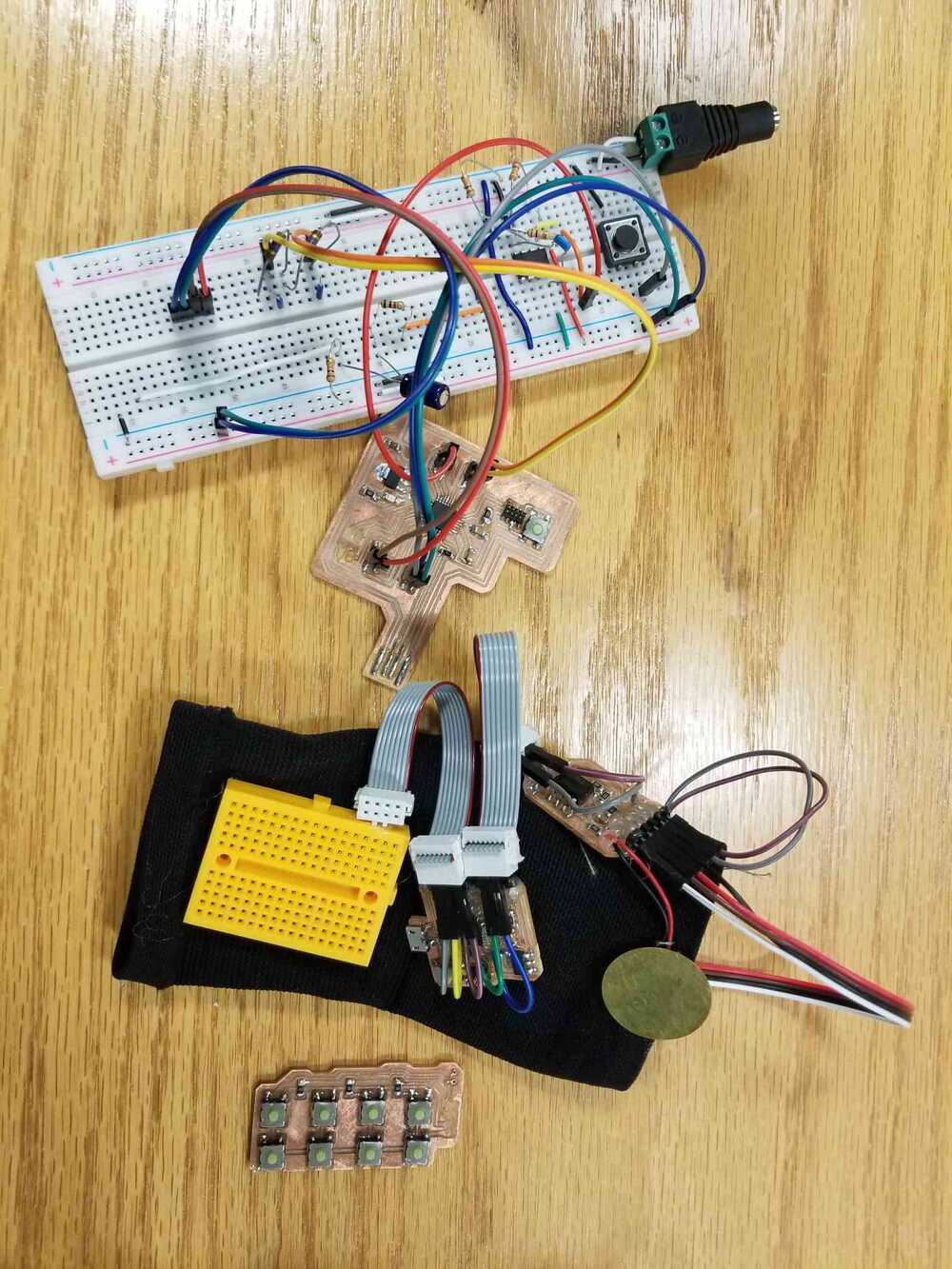
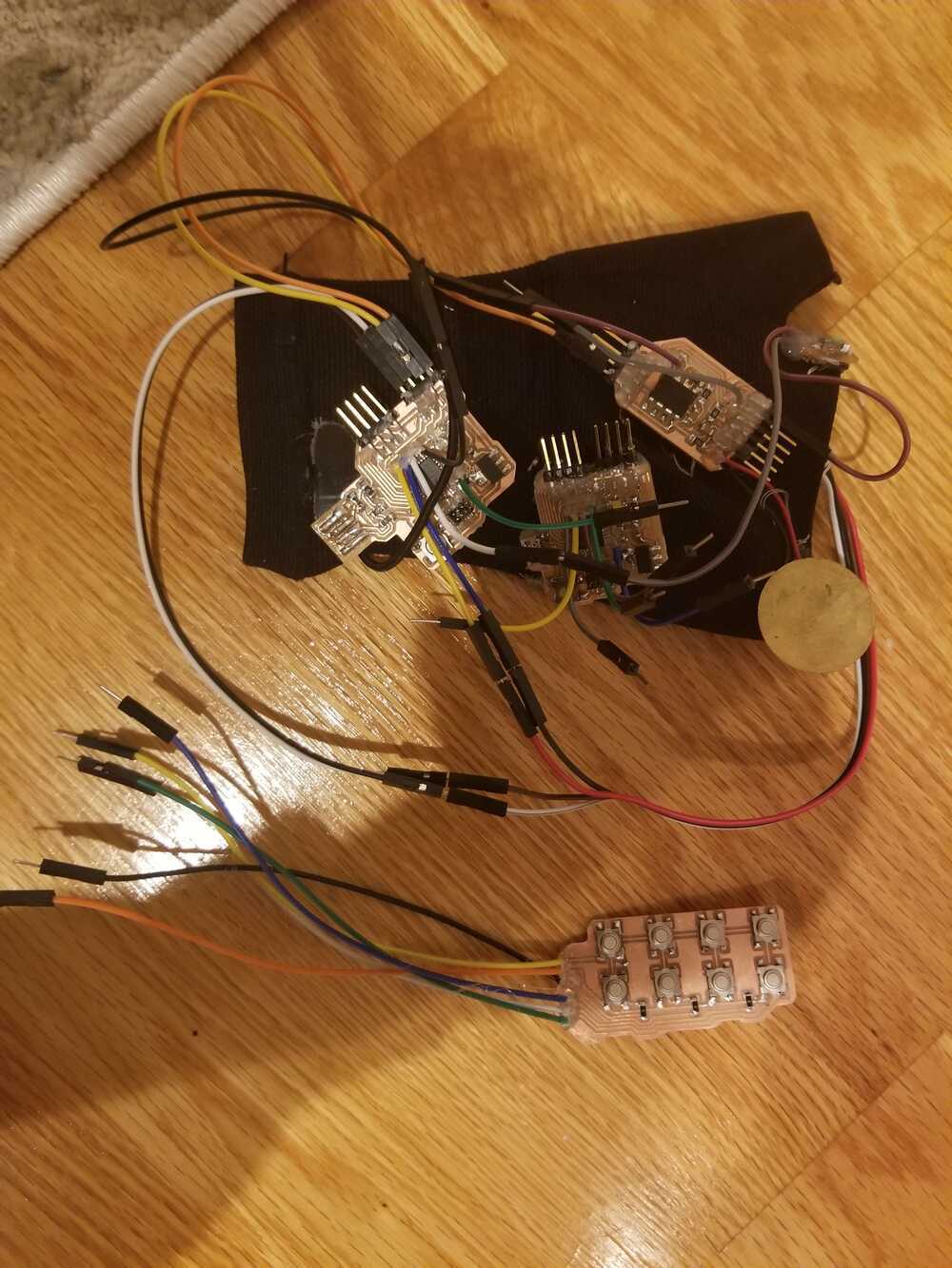
We were entering into project crunch time and having to reprint and resolder these boards over and over was really taking its toll. After hooking up the new boards, I focused on writing software. I combined the functionality from week 6 with the FFT code for the contact sensor and tested it on the boards. After a while and despite my hot glue-ing of all the contacts, the jostling of the boards gradually deteriorated the stripped wire connections. I had to sort of frankenstein the new board to the glove and rewire everything using free wire in order to get something working again for the showcase :/
The board at the bottom of the glove is just a copy of the middle board; I just didn't have the opportunity to switch them out properly :/
Unfortunately for me, this ruined my neat wiring and prevented me from getting to my reach goal of measuring out a suitable housing for the circuits. Regardless, I reached all of my minimum project goals and was able to present a working prototype at the showcase!
So I guess that's a wrap for now. I definitely see myself continuing this project in the future!