week 3: design, 3D print, and scan!
the design.
time to think about that final project...
The assignment this week was to design and print a small 3D part that couldn't be created subtractively. To accomplish this, I decided to print 2 connected parts that would move relative to one another when printed. The idea was for this print to be the first prototype for the press control mechanism in my final project.
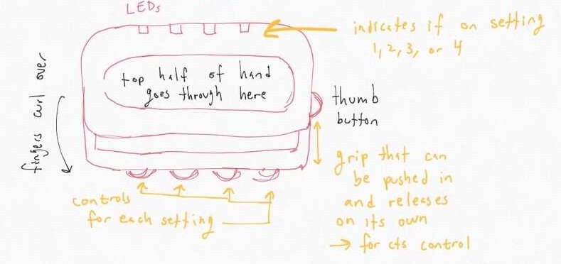
My vision for this control is an in-and-out movement that translates to continuous values in a 0-1 range. On the sensor side, this would likely require a potentiometer. The potentiometer would measure the angle of some spinning/moving part, which means translational motion in 1 axis for one part would have to result in rotational motion in another part. What would also be cool would be for the press control to reset itself when released-- this would likely mean using a spring to push it back out after being pressed. A spring would also add resistance proportional to high values in the 0-1 range which could help the user intuitively approximate what value they are outputting without a numerical interface. I'll address these ideas later in the design process... for this week we are sticking to the 3D printing assignment!
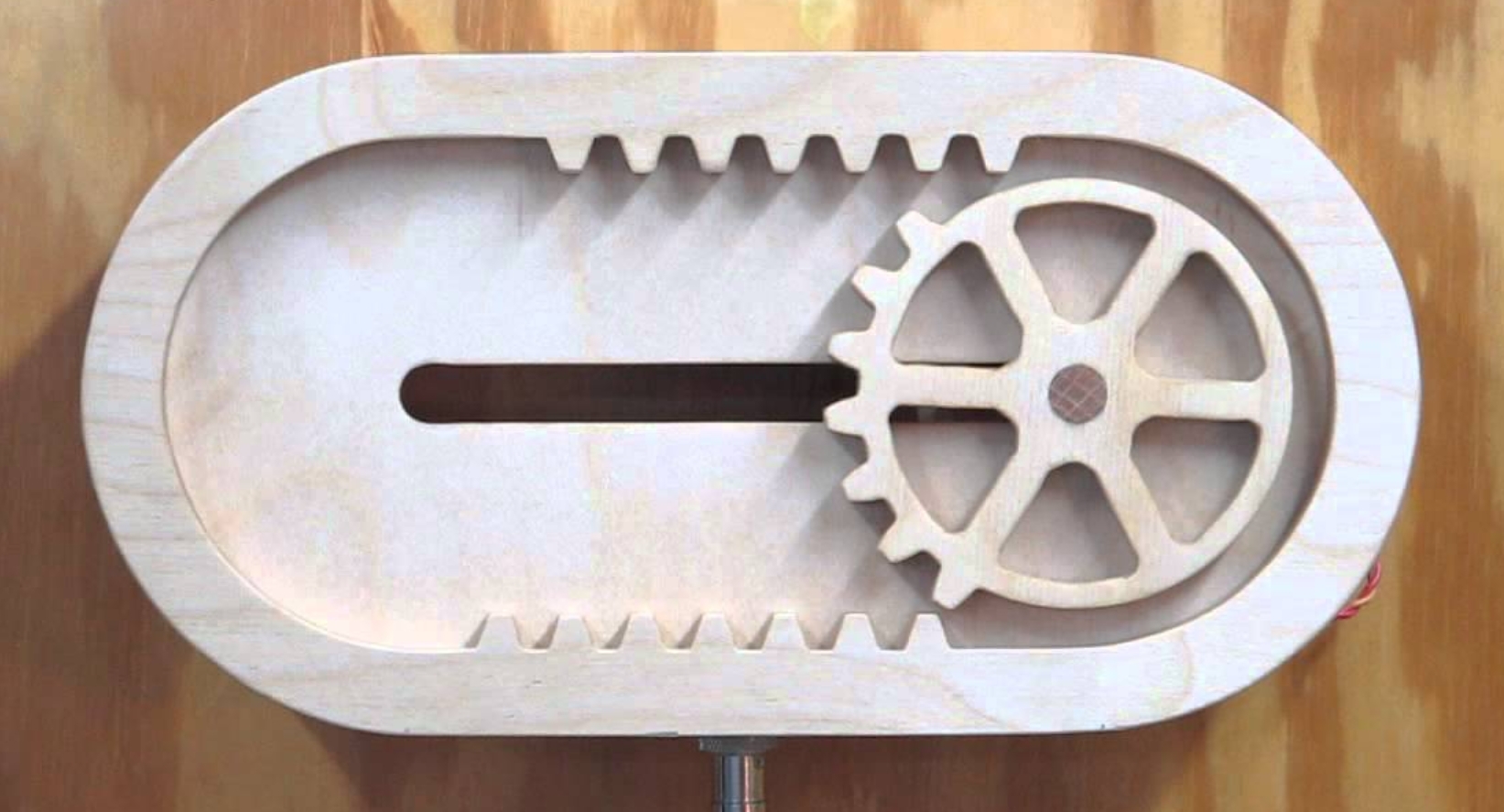
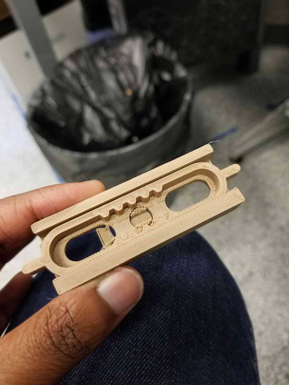
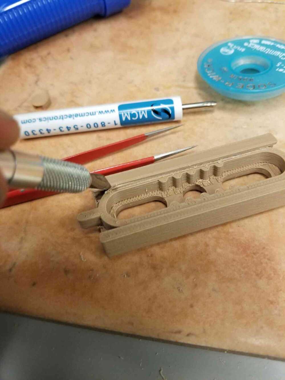
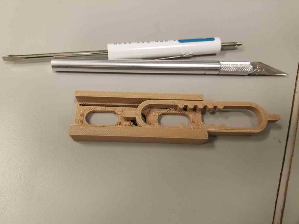
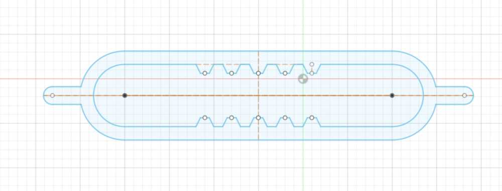
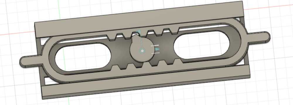
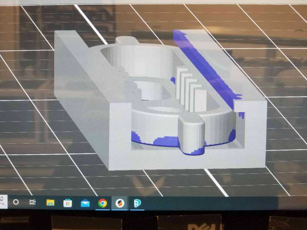
I began looking for some example mechanisms that translated single-axis movement to rotation and ran into the reciprocating gear (shown in the picture above). By holding the gear in place and moving the outside piece back and forth, 360-degree motion should be able to be achieved in the gear. Since most of the potentiometers I have used do not have 360 degree rotation, the gear design, and whether it will turn 360 degrees or less will be left to later weeks when the design requirements become more clear.
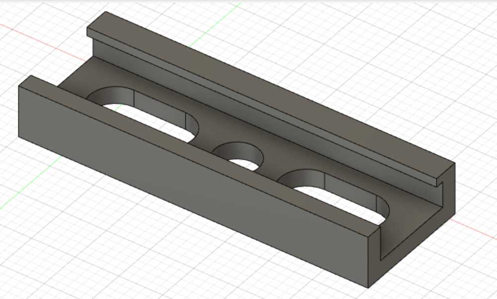
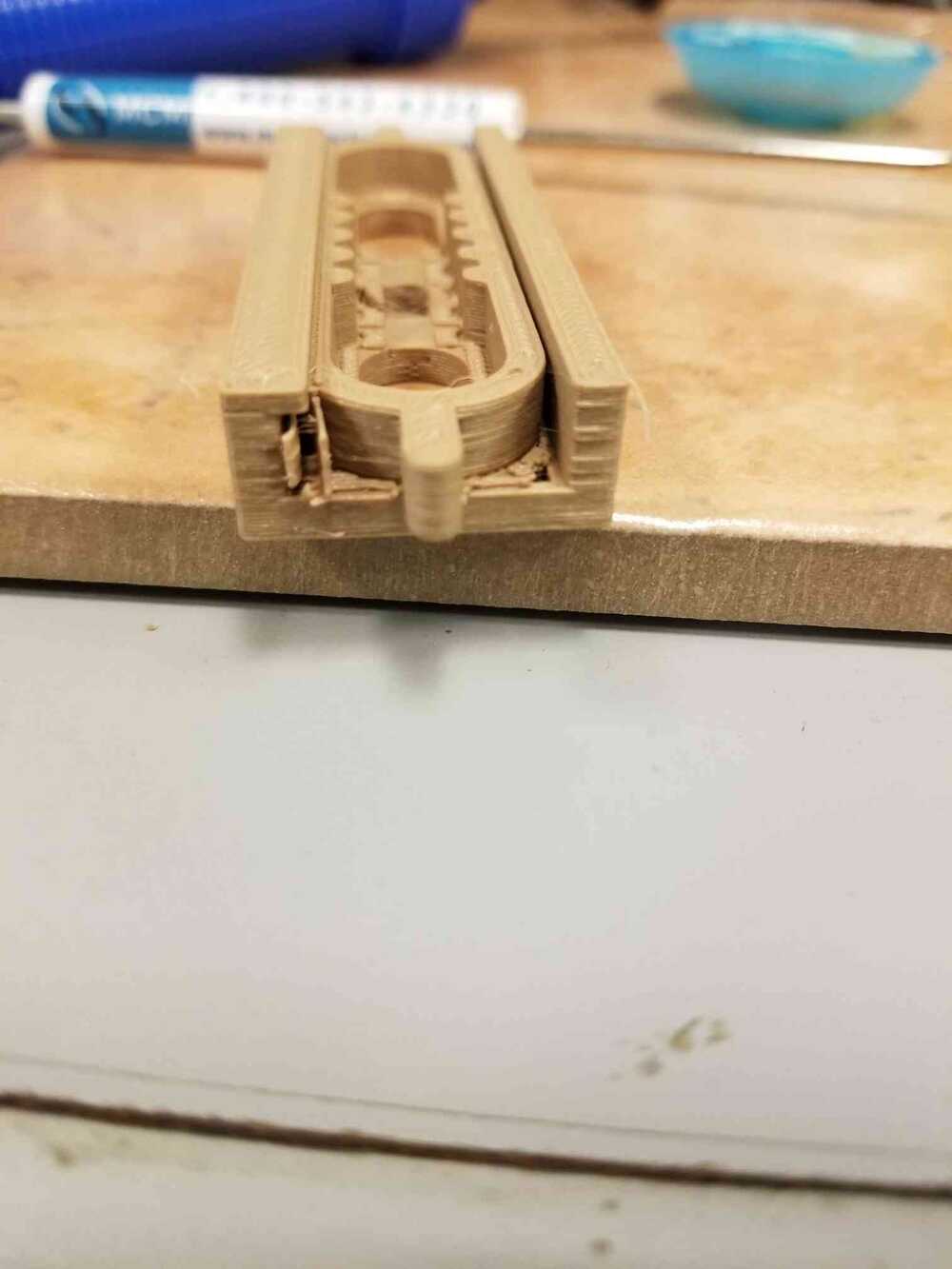
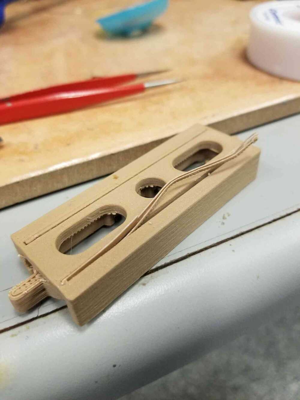
I designed the slider (the part with the teeth that interlock with the gear) inside of a single-axis channel so it could be slid back and forth on a single axis. I left a hole for the gear and removed some additional areas from the channel in order to decrease print time. I also removed areas near the edge of the channel in order to create space for supports that would lift the slider piece inside the channel so it would not stick to the channel itself during printing. I gave the slider about 0.5 mm or less of wiggle room inside of the channel to account for material expansion/shrinking and to allow for supports to be printed between the parts. I also placed an overhang in the channel on one side to determine whether it would be necessary to allow the slider freedom to be popped out in order to remove supports.
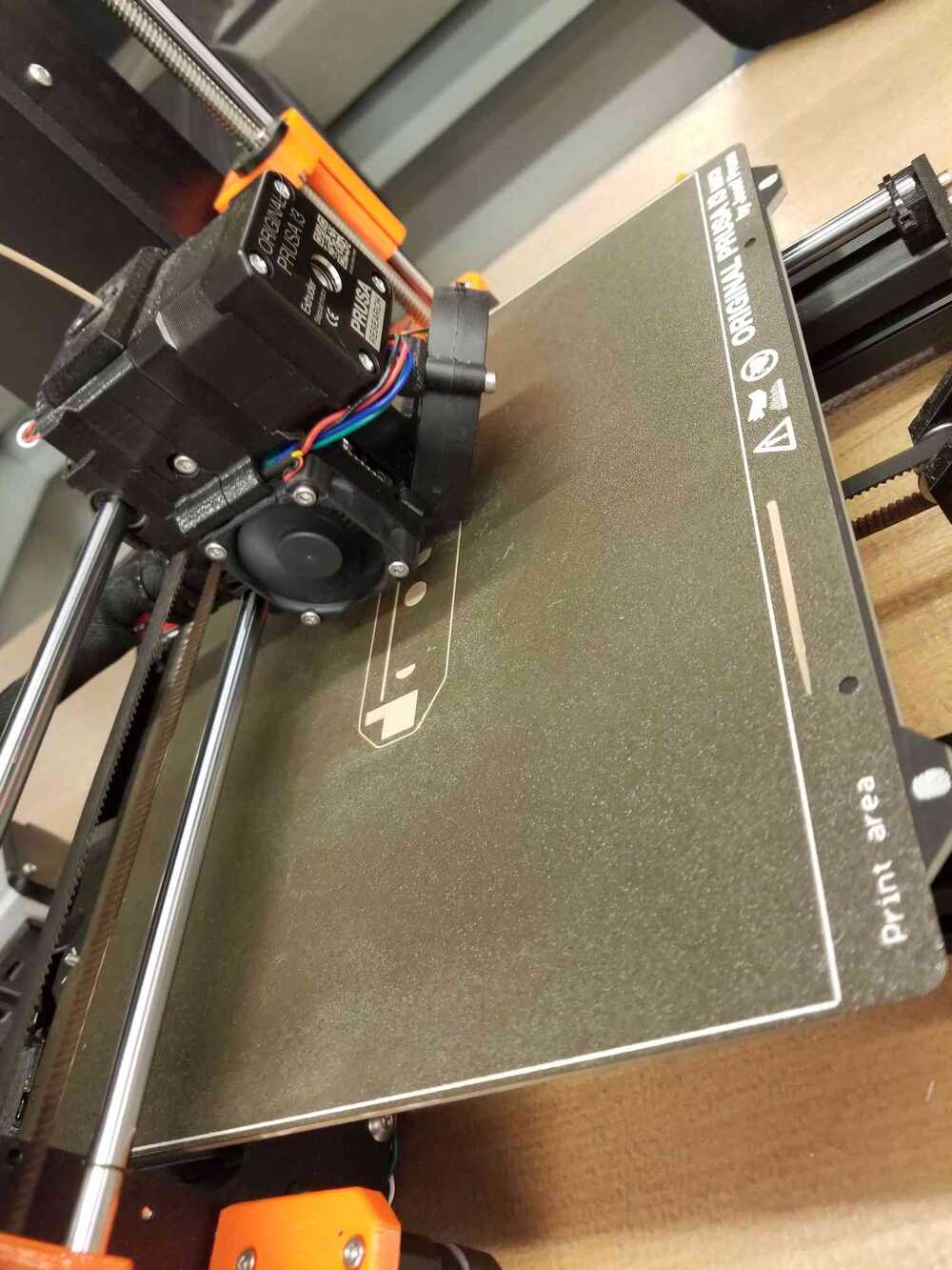
Because of the nature of my part, it was recommended I use dissolvable supports so I wouldn't have support residue left back on my part that could impede motion. Unfortunately, a printer with dissolvable supports was not available to me during my lab time so I took tried using the Prusa 3D printer. When setting up the print, I decided to paint on supports since the generated supports were tying the slider and channel together at too many places. I placed supports in the openings in the bottom of the channel, 1 layer of supports between the lever and channel, and supports under the overhang (even though the overhang was small enough to maintain its structure, the proximity to the slider likely would have caused it to stick).
group assignment
I based my printing assumptions on the design rule prints my group printed out to see what angle/overhang length would lead to stringy plastic.