Week 1: Computer-Controlled Cutting
Group Assignment
Group assignment answers can be found here: Group Assignments
Vinyl-Cutting: Croissant
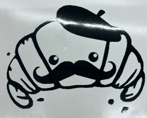
I chose to vinyl-cut a cute croissant. This was the original image:

I used an online image background remover to remove the background, and then cut the vinyl:
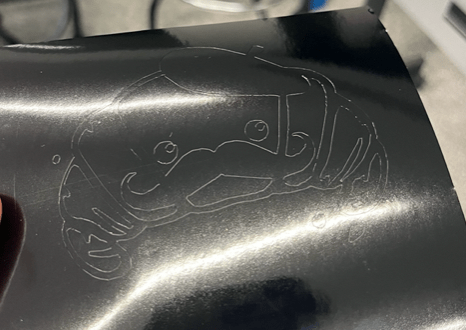
Then I peeled the vinyl:
Then I put on the transfer tape:

The croissant has not yet found a home.
Laser-Cutting: Eiffel Tower
This week, I chose to laser-cut an Eiffel Tower.
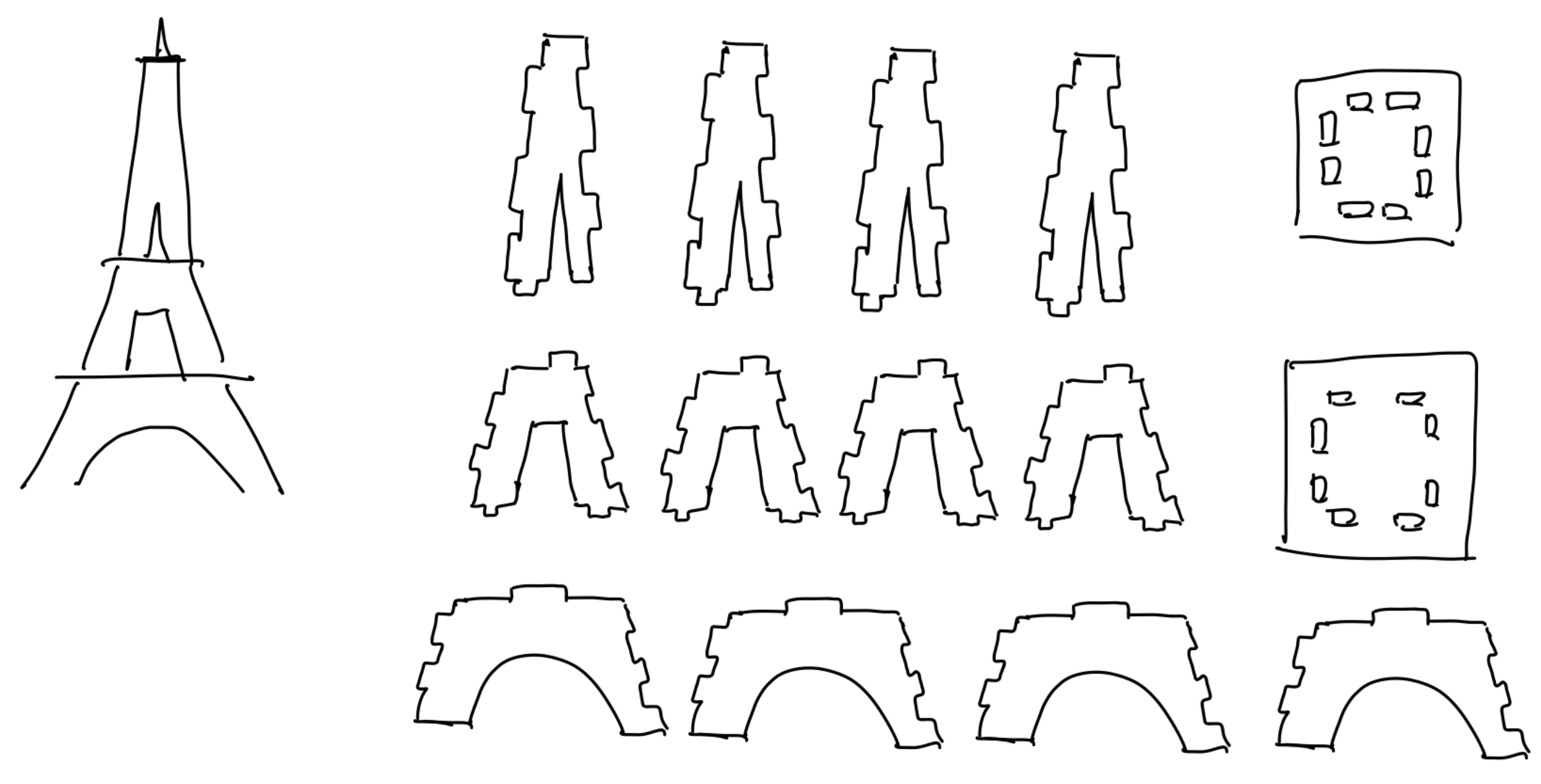
I started by free-drawing the idea of the kinds of pieces I wanted for the structure. I was going to have three different levels, and each level would consist of 4 identical pieces pieced together. Initially, the idea was to have three platforms holding the tower together (and to mimic the different levels of the actual Eiffel Tower).
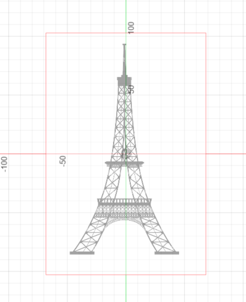
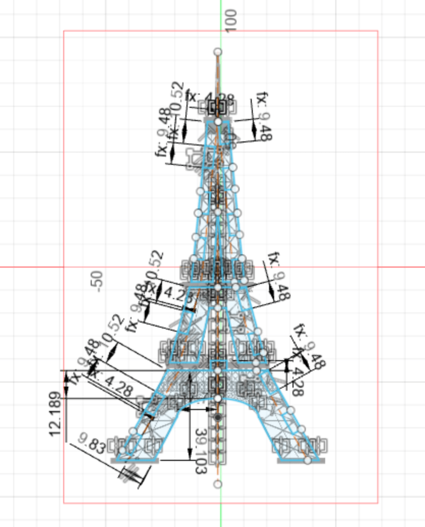
Then, I started working in CAD by uploading an image of an Eiffel Tower that I had found on the internet. The first time I tried this, the picture was really small, so what I did was I sketched the Eiffel Tower on top of it and then calculated the scale ratio I wanted to make the entire thing the appropriate size. I had used a spline to make the curve at the bottom, and what I quickly realized was that splines were not great especially when doing a scale, since they would calculate weirdly. I ended up using an ellipse for the arc at the bottom. This very first time, I also applied almost no constraints, so things would move around a lot.
For cutting out the tabs, I accounted for kerf by using (tabWidth - kerf) for the width of the cut out tab. I then propagated this across a side using the rectangular pattern feature, spacing the pattern out at (2 * tabWidth) so that each tab cut-out would have a distance of (tabWidth + kerf) in between. I first tried this on the upper piece and printed just two pieces, and they fit together.
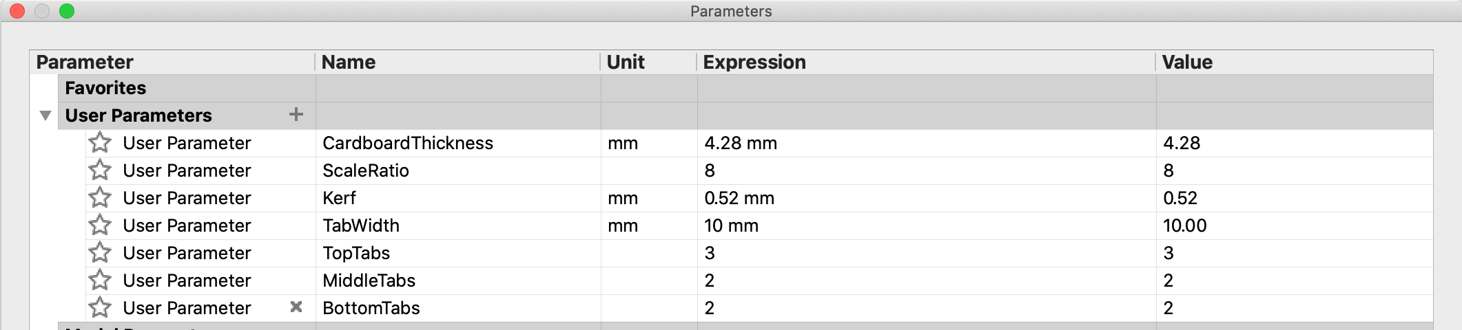
These were all of the parameters I had for this sketch - I realized early on how useful parameters were.
After all the side tabs were completed, I attempted to add the top and bottom tabs that would go into the platforms. Here, I ran into another problem: when I tried to constrain the top tabs to have a height of "cardboardThickness", instead of just changing the tab, it would shift the entire structure. After applying a few more constraints, I managed to add in the tabs. I then tried to extrude the sketches, but in the process I realized that during some manipulation, the tabs had changed size and I didn't know how to revert them.
At this point, I decided it was time to restart the sketch. This time, I scaled up the imported image itself first so it was already the size that I wanted. I drew half of the sketch, applied some constraints (what I had thought was enough), then mirrored the tower to get the full sketch. As before, I added the tabs, but ran into the same problem again of the tower not being fixed enough when I tried to add the top and bottom tabs.
Additionally, when I tried to extrude the sketches so that I could assemble the pieces in 3D to determine what holes I would need to cut out from the different platforms, I realized it would be hard because I didn't know the angles that the sides of the different levels would be at when assembling. So it was time to start over again, but this time starting in the 3D space first instead of in 2D.
I started by constructing planes for the different levels, and then constructing squares and using the loft function to create all of the faces I wanted.
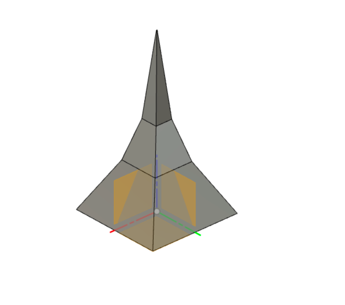
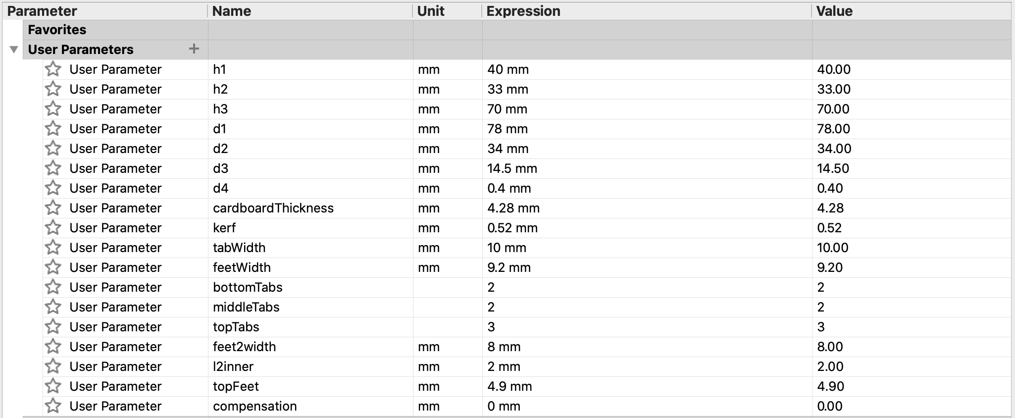
Now, I constructed the sketches directly onto the planes of the faces, in the same manner I had done before, but with additional parametric constraints for different lengths, etc. of the sketch (as advised by Alfonso). This time, with the additional constraints, I was able to add the top and bottom tabs without the rest of the sketch moving.
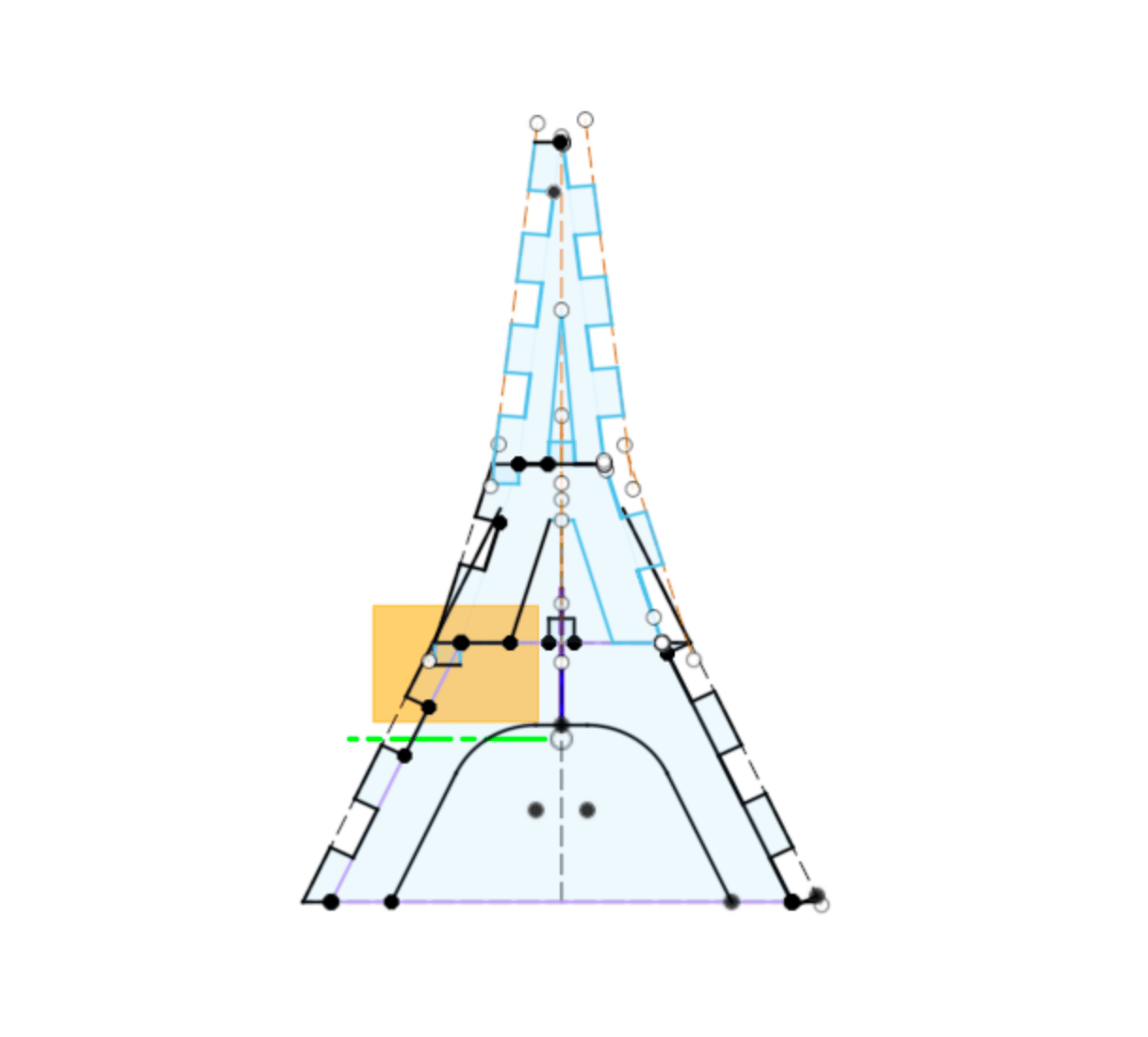
The following parameters were used:
I extruded the sketches outwards, and used a circular pattern to be able to assemble each level with four repeating pieces. However, I noticed that the bottom level had tabs that intersected a decent amount, more than I would think even considering the kerf. This was likely due to the angle of the pieces, because the joints were meant to be orthogonal but the assembly wasn't. I tried to account for this by increasing the size of all of the tab gaps on the bottom level, so the model would show less tab intersection. Instead of the gaps being of length (tabWidth - kerf), I made them (tabWidth - kerf + compensation), where compensation is a parameter.
Before compensation:
After compensation:
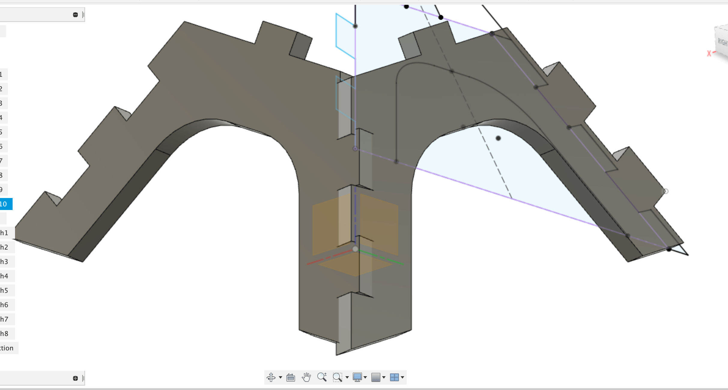
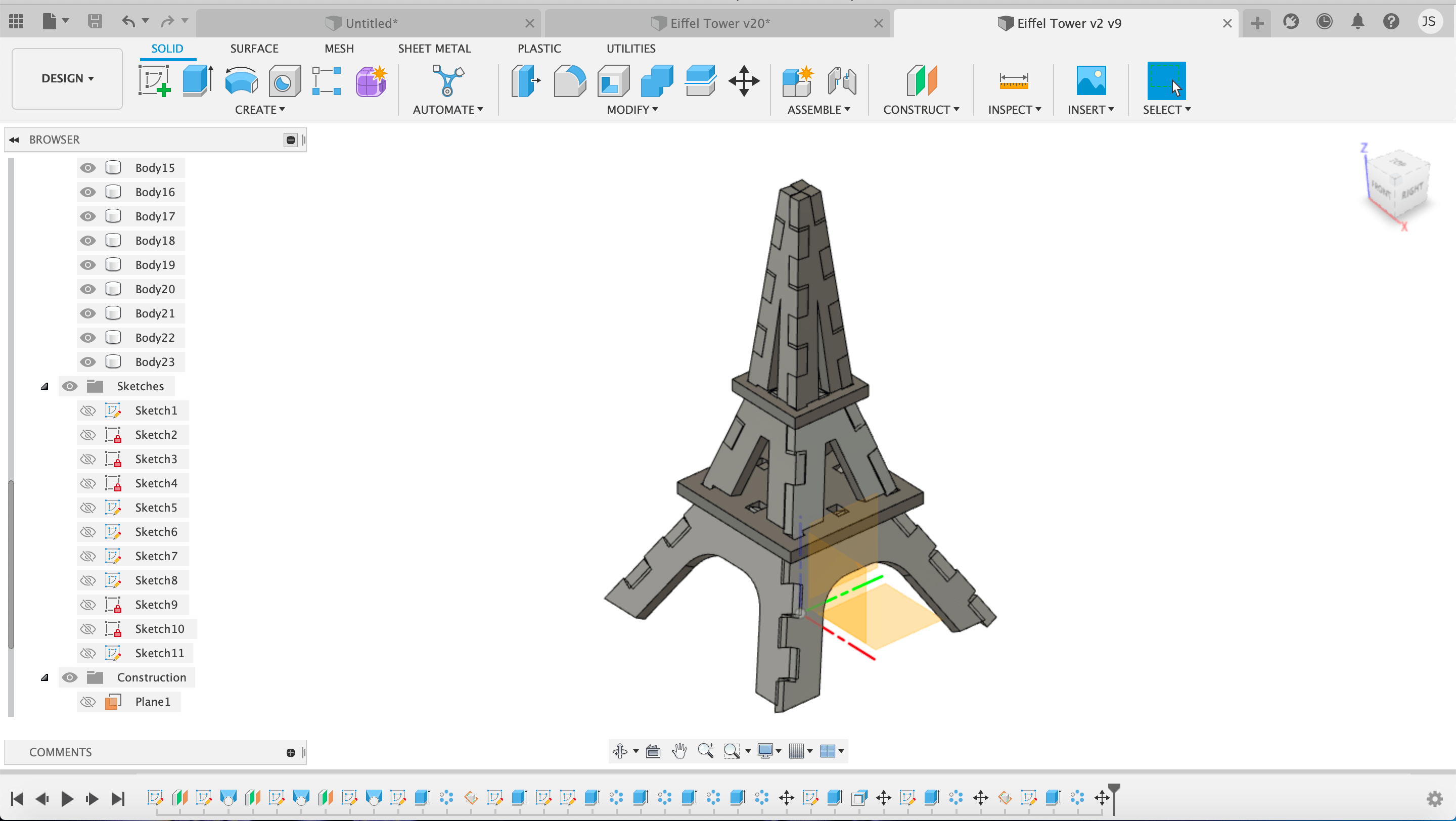
I then used the assembled pieces to create a plane and then the platform that goes in between each layer. I projected parts onto the platforms to determine exactly where the tabs would intersect, so I would know what to cut out from the platforms.
I now had a full assembled structure that I could create sketches from to send to print. The top view of the model also looked really cool.

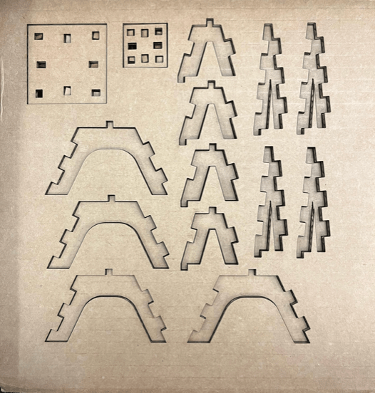
Printed:
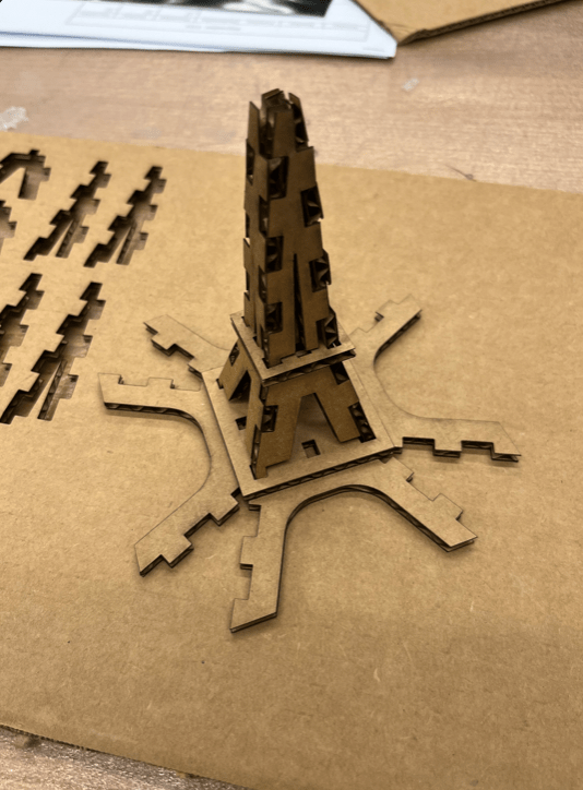
I started the assembly by assembling each of the identical groups of four. The top two were great (though I did need to wiggle the pieces in a bit), but I realized that the bottom pieces were way too loose, and they were not holding together.
I went back and changed the parameter for "compensation" to decrease it, and in the final version, I actually ended up not using any compensation. Even though there was overlap in the 3D construction, the kerf probably helped decrease it enough that the pieces would fit in with a little bit of manipulation and force.
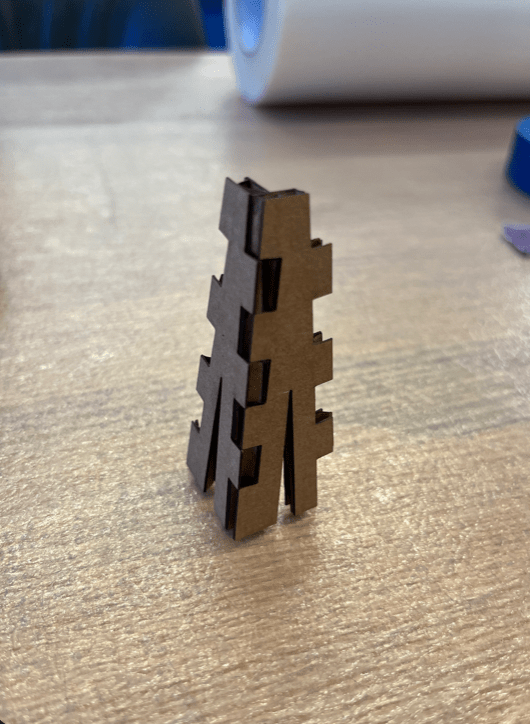
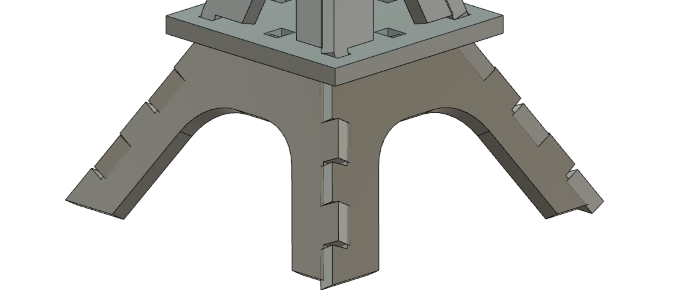
This is the final assembly!

Unfortunately, the pieces fit a bit loosely into the platform so it detaches quite easily, likely due to the fact that I forgot to account for kerf when cutting out the holes in the platform but also likely due to the fact that the tabs go into the platform at an angle so it's not a snug fit.
The final tower is by no means good or perfect, but it more or less worked and can stand on it's own. To iterate on it though, I would try to figure out how to make the three layers assemble more solidly into the platforms, first by accounting for kerf but also possibly by adding more tabs and holes so there is more contact and therefore stability.
As a final recap, some of the lessons I learned from this include the importance of using parameters, adding as many constraints as possible, starting simple and then building up from it, and the usefulness of working in 3D from the start.