Week 8: Input Devices
Group Assignment
Group assignment answers can be found here: Group Assignments
PCB Boards
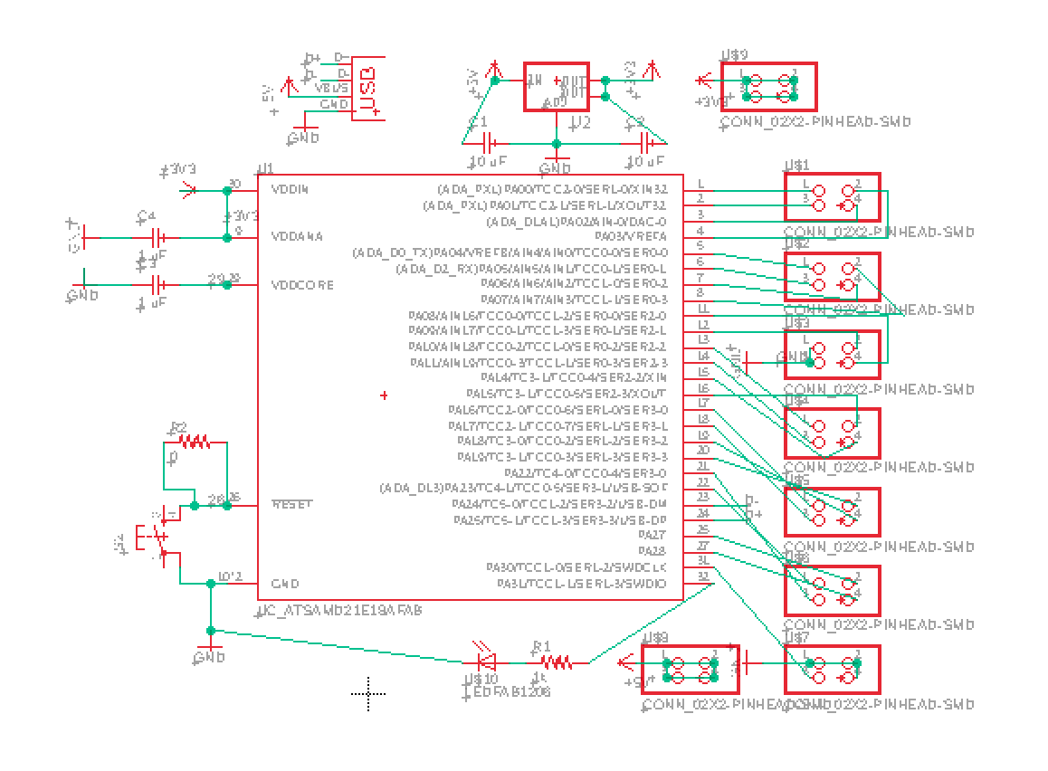
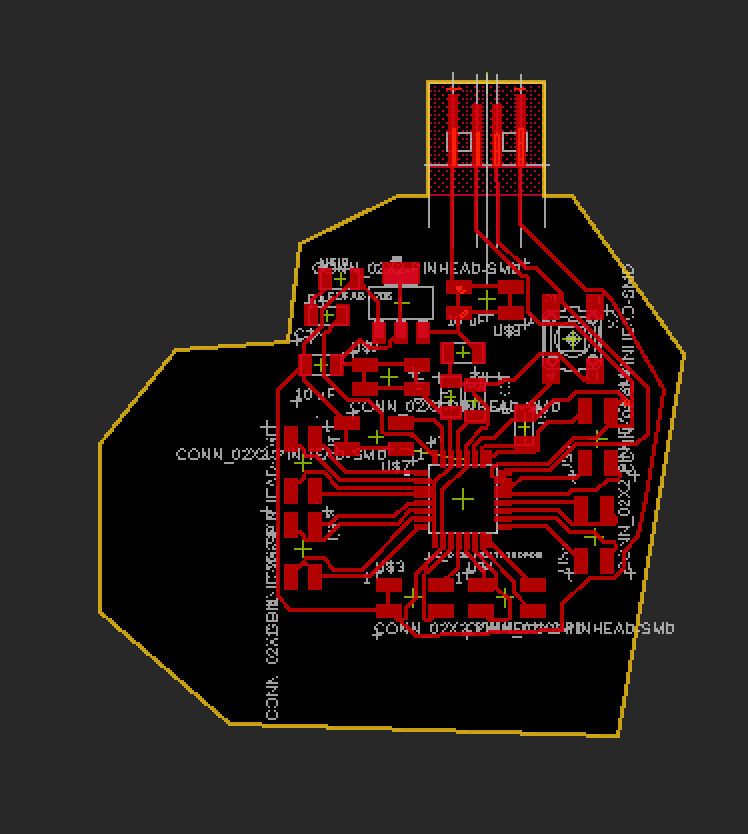
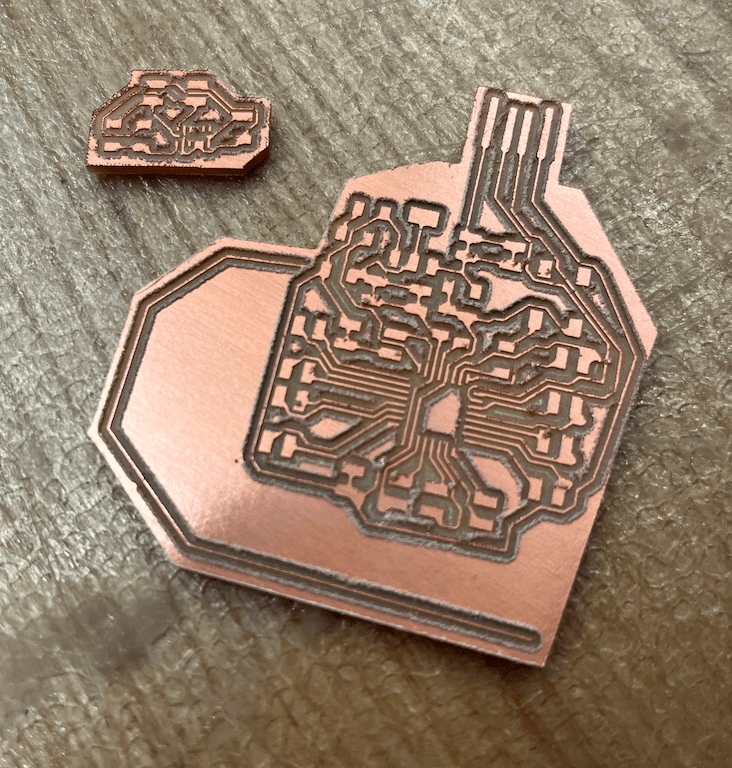
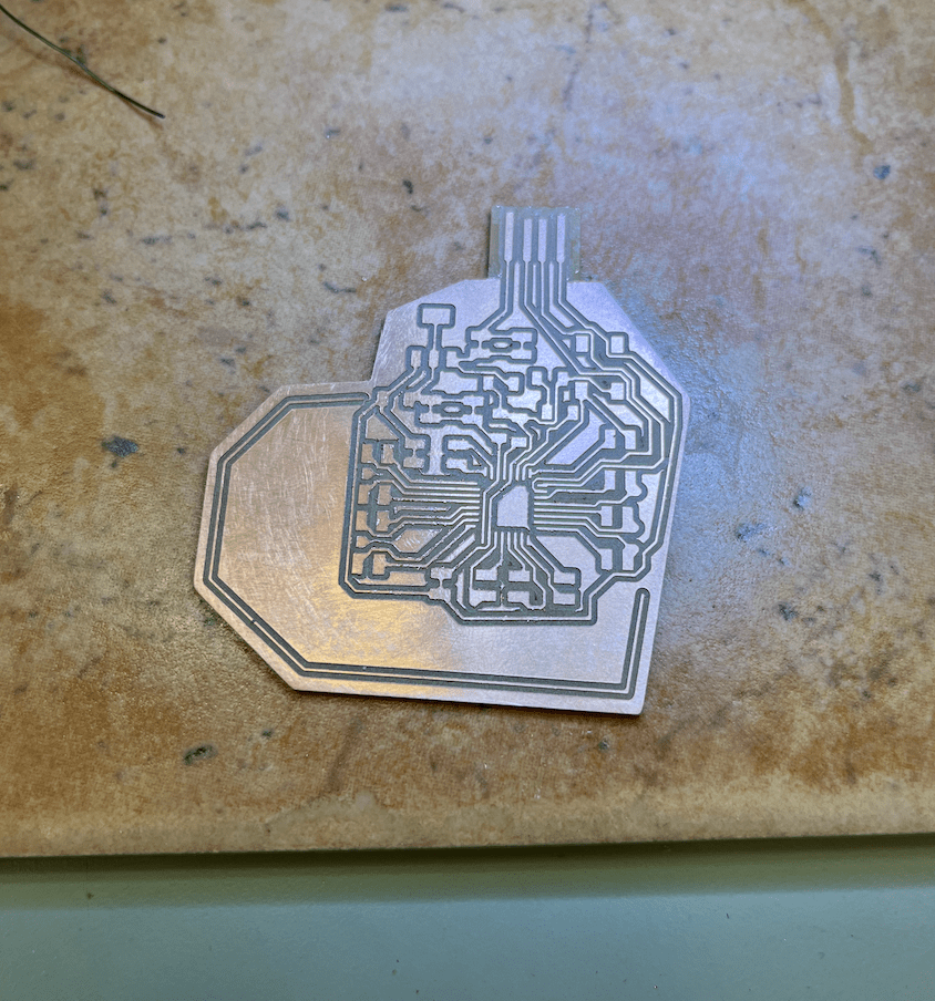
This week, our assignment was to program a board that could take input from an input device. I chose to use an accelerometer because my final project will likely be some sort of lamp that includes the feature of turning on by tapping the lamp. Before getting to the actual input device part though, I had to remake a board. Previously, I had used the SAMD11C, however Anthony recommended switching to the SAMD21E. He also recommended creating a central board that could then be used to break out into smaller input boards. I designed the main breakout PCB by essentially just using a bunch of 2x2 pins and connecting microcontroller pins to header pins. I also included extra headers such that I would have 3-4 total pins of each of ground, 3.3V, and 5V. I added a reset switch like Jake's recitation example video showed, and I also threw in an LED so that the board could light up. I also cut my board out in a heart shape, which was qutie hard to draw freehand in Eagle. The idea of the LED was so that I could make the heart red with red light. It honestly took so much time trying to route the board, and it was very much a reiterative process of routing then changing schematic then routing again, but I managed to finish it in the end with just one 0 ohm resistor!
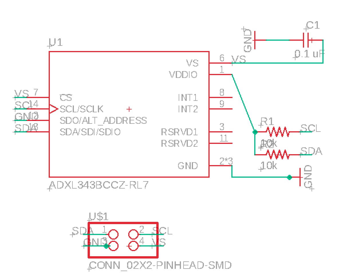
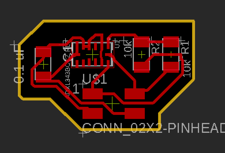
Then, for the accelerometer breakout board, I followed an example board from the website and included the required resistor and capacitor components, finally also connecting everything to a header pin so the connections could be make with the main board.
After milling the boards out, I sanded the boards down a bit so the copper splinters would be removed along the sides of the traces.
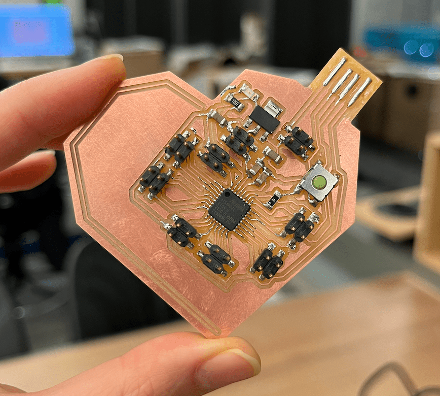
Stuffing the board was much quicker than I expected, and since all the finer soldering irons were occupied at the moment, I somehow managed to solder almost the entire main board with the less fine and I think cheaper soldering irons that the other classes use. Didn't even need to use soldering wick this time!
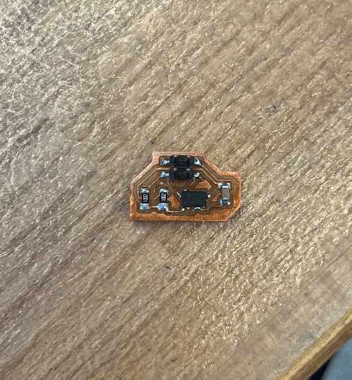
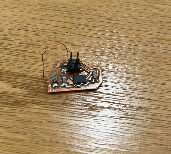
Stuffing the accelerometer board was a bit tricky with the input device, since the accelerometer had no legs, and only had metal underneath the part (except the part covered the traces entirely). Following Alec's advice, I first put solder on all of the traces for the part. I then put flux on the bottom of the part, and used the heat gun to attach the piece. Not sure if this worked or if there are shorts underneath because I wasn't sure exactly how much solder to put on each leg, but hopefully it'll be okay. I'll find out when I start testing.
Programming the Boards
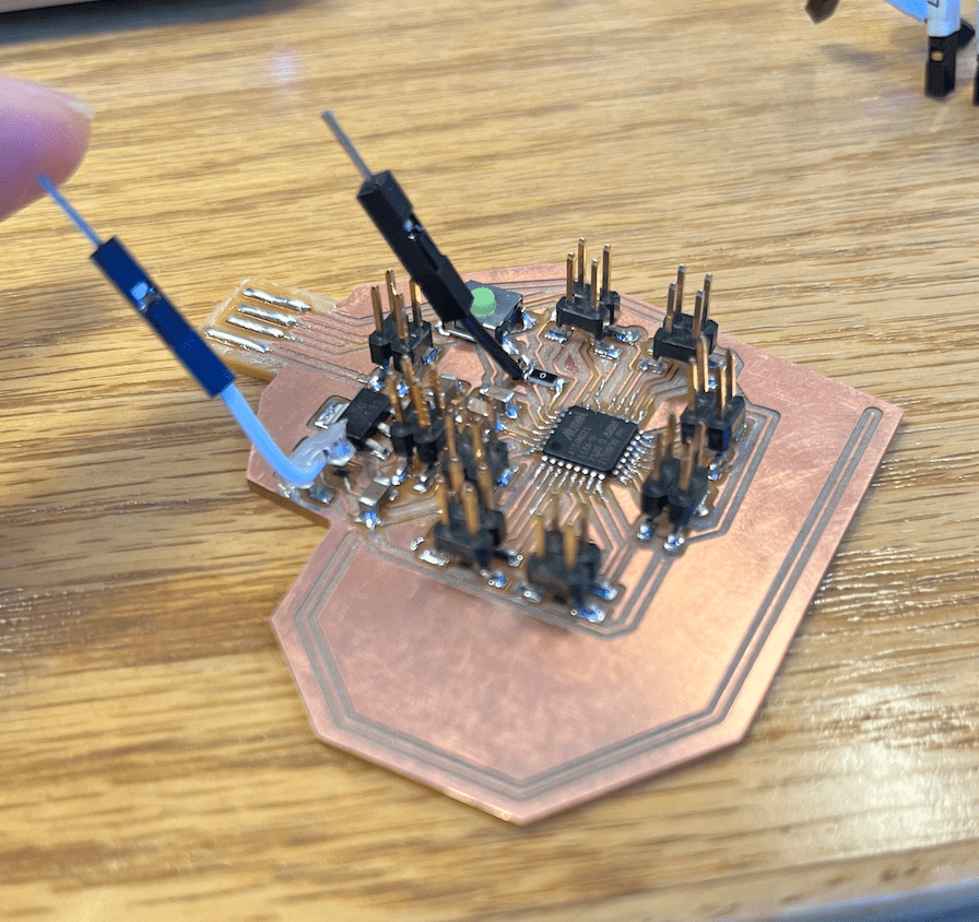
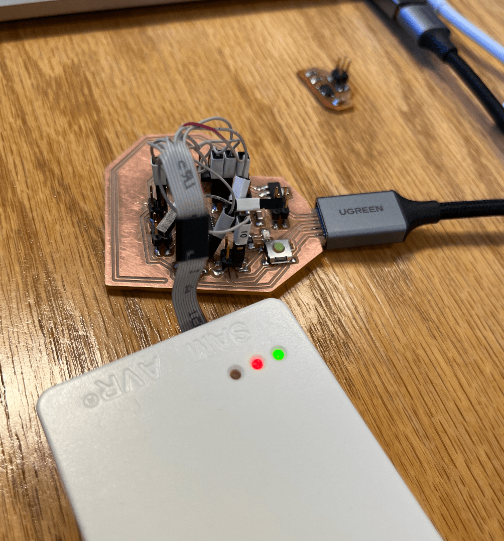
After I finished stuffing the boards, I started trying to program them. Because I didn't keep the 10-pin header on my board and replaced everything with 2x2 headers I had to connect the SWD pins invidually to pins on my board. Then, I realized I had pins missing. When I was designing the board, I didn't realize I needed actual pins for the SWDIO and RESET pins on the microcontroller. The RESET pins I had connected to the button, and the SWDIO pin I just didn't know was important so I had treated it as a random pin and connected it to the LED. I tried to fix these by attaching wires to the relevant traces. I had to sacrifice the LED for this (sad), and this would probably have caused the reset button to stop working too. When I attached the wire to the SWDIO trace, the trace started coming off the board. Anthony suggested putting hot glue on which I did, and it seemed to hold for a bit, but then the trace ended up breaking because the hot glue also came off the board. At this point, I determined continuing with the board was a lost cause.
I ended up milling a new breakout board with the correct connections, and successfully stuffed and programmed it. I made the connections based off of the SWD pinout guide, and got the bootloader loaded onto it. For some reason, it wasn't working when I tried to use Arduino directly to load the bootloader, but it worked when Anthony loaded it from his computer.
Accelerometer
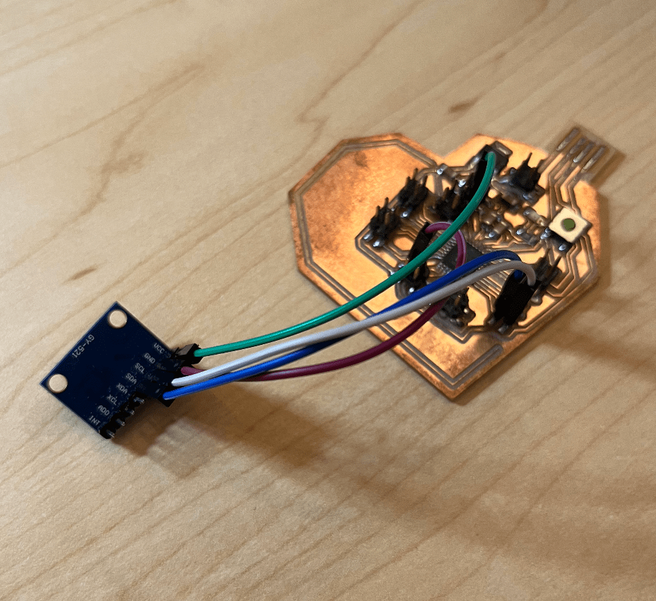
Now that the breakout board was programmed, I needed to get input from my accelerometer. I attached the pins on the accelerometer to the corresponding SAMD21C pins. It wasn't working, so it was time to debug with Anthony's help.
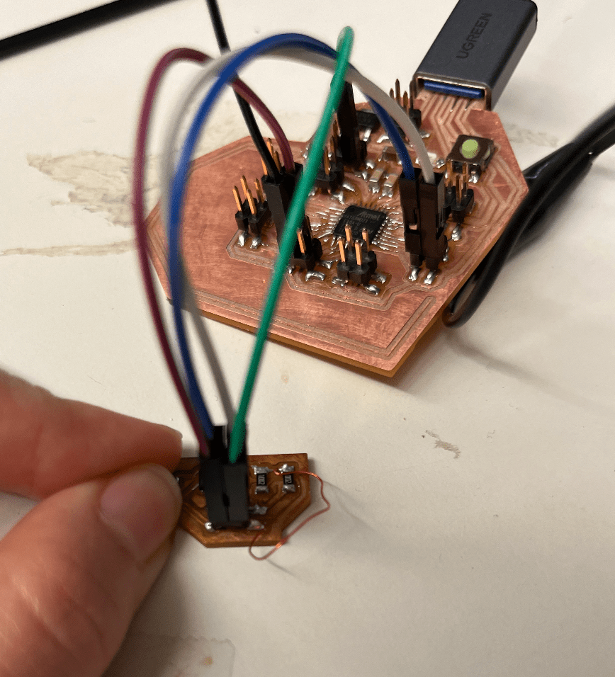
The first thing we did was add more solder to the bottom of the ADXL343, because Anthony thought it was possible the connections weren't good enough. I learned here the usefulness of using solder paste in these situations (because you kind of just put paste all over the board and then it'll shrink so there's only solder on the metal parts), but that it was easy to either use not enough or too much. After we fixed that, it still didn't fix the problem. We tried using the oscilloscope, but for some reason the data line was low. The next thing we realized was that my accelerometer was actually missing a connection. I fixed that by making the connection with some magnet wire. We were hoping that would fix the problem, but it still didn't. It was weird because the accelerometer was now being detected, but it wasn't able to read anything and the example code I was running was getting stuck somewhere.
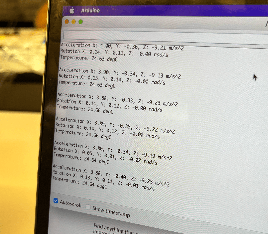
After many hours of trying to debug, Anthony ended up just giving me a commercial MPU6050 accelerometer to use. Once that was connected and I had the MPU6050 library loaded into Arduino, the example code ran beautifully and I was able to get input from the accelerometer! It was just kind of sad that we couldn't figure out what was wrong with my accelerometer though...
Lessons Learned: breakout boards are very useful and make things much easier later on (though they do take a lot of time in the beginning to try to figure out), solder paste can be quite useful for soldering difficult things if you know how to use it well, making shapes freehand for a board is quite hard to do (re: my heart-shaped breakout board)
Useful links:
SAM D21E Data Sheet: https://cdn.sparkfun.com/datasheets/Dev/Arduino/Boards/Atmel-42181-SAM-D21_Datasheet.pdf
Adafruit ADXL343 example code: https://learn.adafruit.com/adxl343-breakout-learning-guide/arduino
SWD pinout (for connections for programming board): https://learn.sparkfun.com/tutorials/arm-programming/jtag-and-swd
LED brightness adjustment: https://www.deviceplus.com/arduino/the-basics-of-arduino-adjusting-led-brightness/
ADXL343 Data Sheet: https://www.analog.com/media/en/technical-documentation/data-sheets/adxl343.pdf
ADXL343 Example Board: http://academy.cba.mit.edu/classes/input_devices/accel/hello.ADXL343.png
I2C Device Sketch (to find a device): https://playground.arduino.cc/Main/I2cScanner/