Week 0 - Computer-aided Design (CAD)
This week consisted of an introduction and to the How to Make (Almost) Anything course and briefly covered computer-aided design tools. The weekly assignment covers raster, vector, 3D, and simulation modeling of a potential final project. The most difficult part of this assignment was choosing a final project with the proper scope to pursue, as it is beneficial to do each week's assignment with the final project in mind. I admittedly lack creativity/inspiration for such open-ended project because my mind immediately goes to the most complex thing that I would love to build, but which would cost millions of dollars and take years...
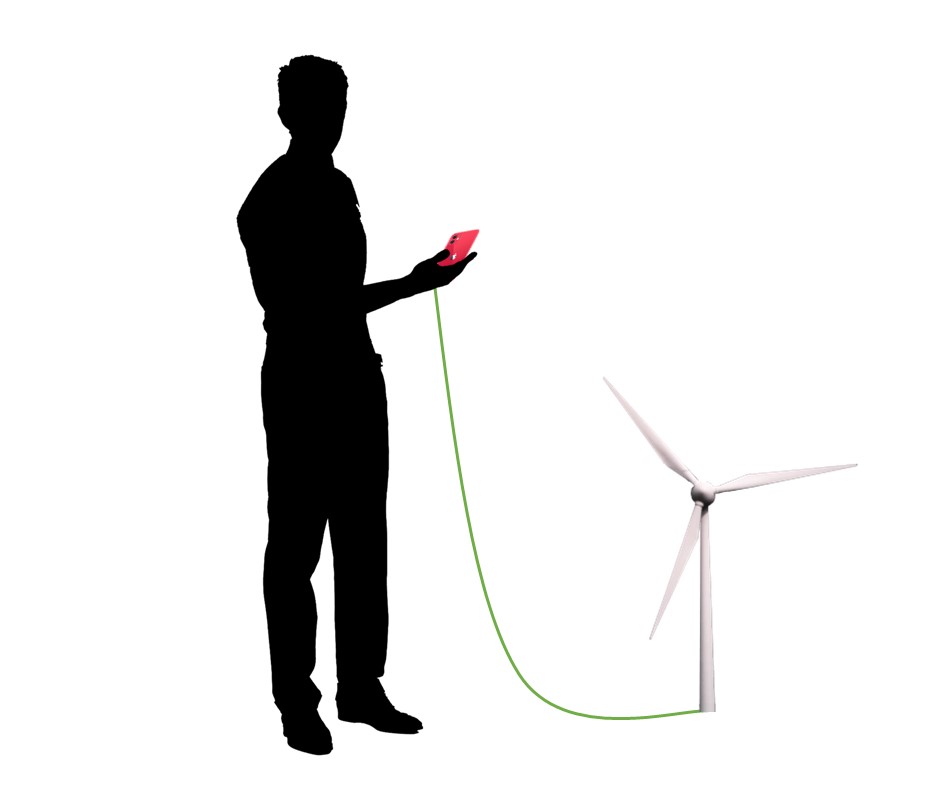
While I'm not confident that this will be my final project idea, I decided on making a simple electric generator with adjustable winding configurations to raise and lower voltages at different speeds. The idea comes from the need for a versatile generator in under-developed regions where the energy source, whether its a river, wind, waterfall, etc. creates uncertainty in the operating speed and therefore output voltage.
I decided to use Autodesk Inventor for modeling and the open-source software, FEMM, for 2D EM simulations, as I have extensive experience with both. While I would love to learn FreeCAD for modeling due to it's open-source nature, initial attempts proved that it not as intuitive as Inventor and the learning curve is a little steeper than I expected; better save that for my free time outside of class.
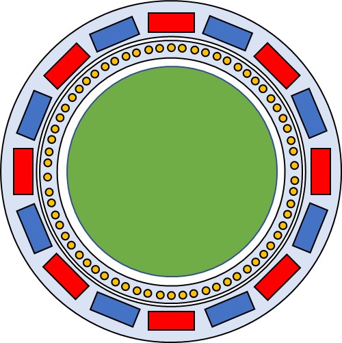
I started by quickly sketching the generator topology in Powerpoint, one of my favorite engineering tools. The generator will be an air-core armature with an outrunner rotor consisting of Ceramic Grade 8 permanent magnets. Based on the 0.875" x 1.875" x 0.375" magnets available in the class inventory, I roughly figured the machine should have 16 poles and 3-phases. With the voltages relatively low due to the air-core nature and likely low speeds, the conductors should be on the larger-end, 12 AWG or below, to handle the current. A PCB will attach to the end of each winding slot and have paths with transistors to select series and parallel connections.
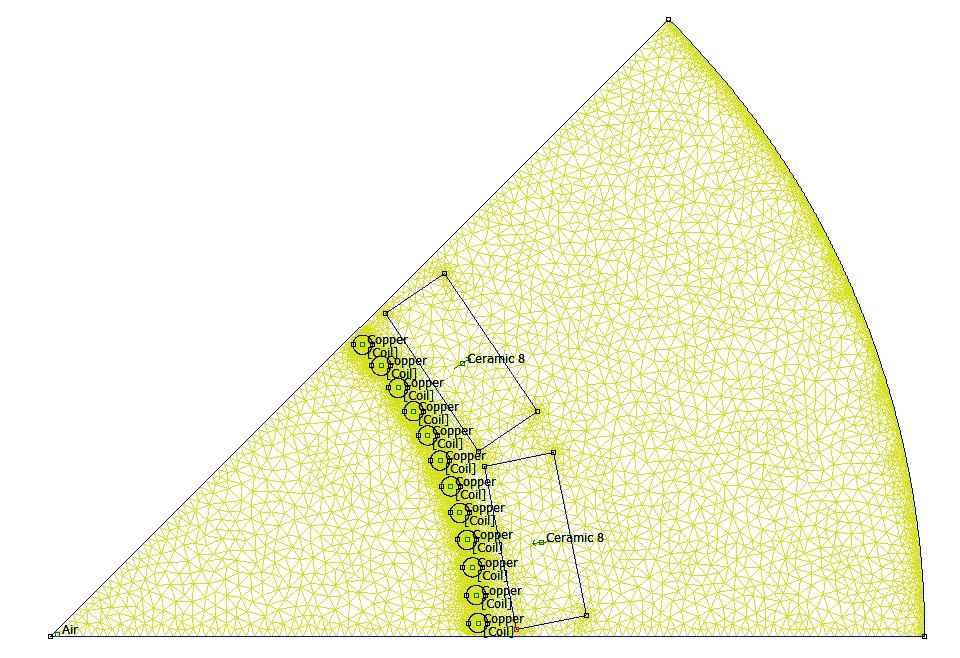
To determine tolerances and back out the number of slots per pole per phase and conductor diameters, I decided to run a magnetic simulation in FEMM, an open-source FEA software. I defined the design in terms of various parameters and scripted an automatic geometry generation code in MATLAB for analysis of a pole-pair section of the motor.
clear
clc

openfemm; % opens FEMM

% Constants (kms)
mag_dep = 0.0254*1.875; % magnet depth [m]
mag_width = 0.0254*0.875; % magnet width [m]
mag_height = 0.0254*0.375; % magnet height [m]
gauge = 10; % armature conductor gauge [AWG]
ds = (0.127e-3)*92^((36-gauge)/39); % conversion of AWG to diameter [m]
spppp = 2;% slots per pole per phase
poles = 16; % number of poles
phase = 3; % number of phases
mag_r = 0.0254*5.2/2; % radius to center of magnet [m]
wire_r = 0.0254*4.5/2; % radius to center of conductor [m]
I = 0; % coil current [A]
pie = 2*pi/(poles/2); % angle spanned by one pole pair [rad]

newdocument(0); % create magnetic problem
mi_getmaterial('Copper'); % add copper material from library to list
mi_getmaterial('Air'); % add air material from library to list
mi_getmaterial('Ceramic 8'); % % add Ceramic grade 8 material from library to list
mi_addcircprop('Coil',I,0); % create one coil
mi_addblocklabel(1e-3*cos(pie/2),1e-3*sin(pie/2)); % add label for air
mi_selectlabel(1e-3,1e-3); % select label
mi_setblockprop('Air',0,0,'',0,0,0); % set to air

% conductors
dtheta = 2*pi/(2*phase*spppp)/(poles/2); % angle between conductors
for n = 0:(2*phase*spppp-1) % iterate through conductors in pole pair
    x = wire_r*cos(n*dtheta+dtheta/2); % x of center of conductor
    y = wire_r*sin(n*dtheta+dtheta/2); % y of center of conductor
    mi_drawarc(x-ds/2,y,x+ds/2,y,180,1); % draw bottom half of circle
    mi_addarc(x+ds/2,y,x-ds/2,y,180,1); % draw top half of circle
    mi_addblocklabel(x,y); % add label to center of conductor
    mi_selectlabel(x,y); % select label
    mi_setblockprop('Copper',0,0,'Coil',0,0,1); % set to copper and coil
    mi_setgroup(1); % set conductor to coil group
    mi_clearselected;
end

% magnets
mi_drawline(mag_r-mag_height/2,mag_width/2,mag_r-mag_height/2,-mag_width/2);
mi_selectsegment(mag_r-mag_height/2,0);
mi_copyrotate2(0,0,3*180*pie/4/pi,1,1);
mi_selectsegment(mag_r-mag_height/2,0);
mi_deleteselected;
mi_clearselected;
mi_selectsegment((mag_r-mag_height/2)*cos(3*pie/4),(mag_r-mag_height/2)*sin(3*pie/4));
mi_copyrotate2(0,0,-180*pie/2/pi,1,1);
mi_clearselected;
mi_selectnode(mag_r-mag_height/2,mag_width/2);
mi_selectnode(mag_r-mag_height/2,-mag_width/2);
mi_deleteselected;
mi_clearselected;

mi_drawline(mag_r+mag_height/2,mag_width/2,mag_r+mag_height/2,-mag_width/2);
mi_selectsegment(mag_r+mag_height/2,0);
mi_copyrotate2(0,0,3*180*pie/4/pi,1,1);
mi_selectsegment(mag_r+mag_height/2,0);
mi_deleteselected;
mi_clearselected;
mi_selectsegment((mag_r+mag_height/2)*cos(3*pie/4),(mag_r+mag_height/2)*sin(3*pie/4));
mi_copyrotate2(0,0,-180*pie/2/pi,1,1);
mi_clearselected;
mi_selectnode(mag_r+mag_height/2,mag_width/2);
mi_selectnode(mag_r+mag_height/2,-mag_width/2);
mi_deleteselected;
mi_clearselected;

mi_drawline(0,0,mag_r+.0254*2,0);
mi_drawline(0,0,(mag_r+.0254*2)*cos(pie),(mag_r+.0254*2)*sin(pie));
mi_drawarc(mag_r+.0254*2,0,(mag_r+.0254*2)*cos(pie),(mag_r+.0254*2)*sin(pie),pie*180/pi,pie*180/pi);
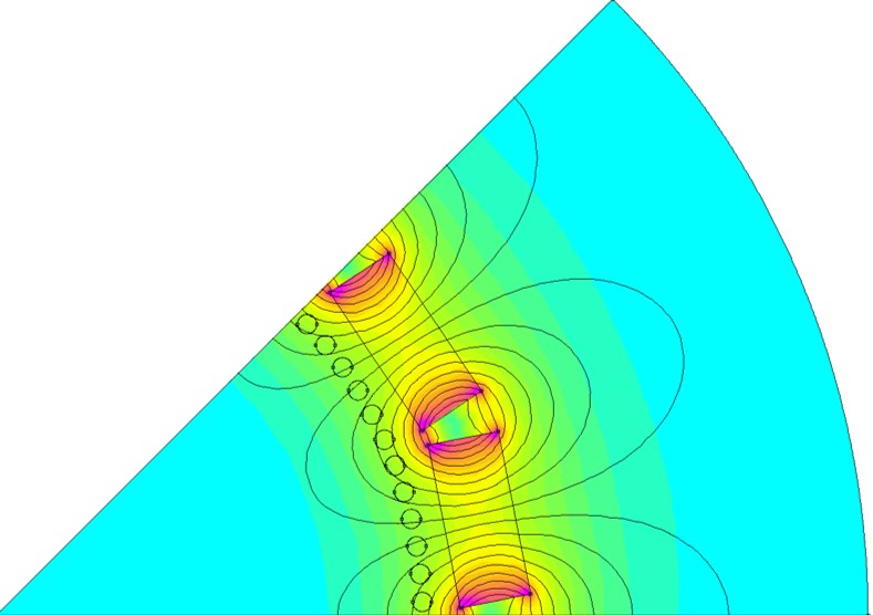
This generated the following geometry and mesh and, after simulation, the following magnetic flux density plots. Periodic symmetry boundaries were enforced.
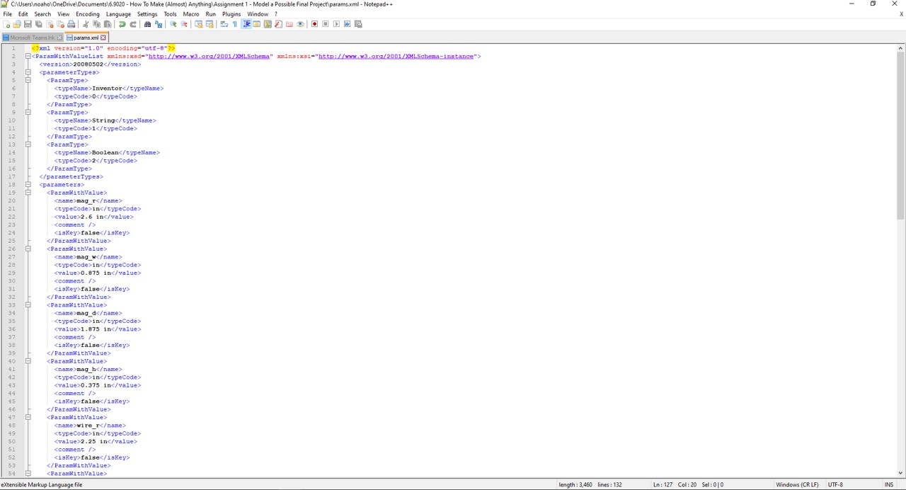
For parameteric 3D modeling, an xml file with a list of design parameter can be read by Autodesk Inventor and change all parts and features by modifying the file and reloading. The xml file looks like the following.
3D modeling in Autodesk Inventor is very intuitive. It involves a number additive and subtractive operations to create the part. There are also very powerful pattern and complex extrusion tools and a great dimension and constraining system. A good rule of thumber is to always ensure the sketch is fully constrained (it notes how many more constraints are needed to fully define the sketch relative to the origin) before finishing the sketch and extruding, cutting, etc.
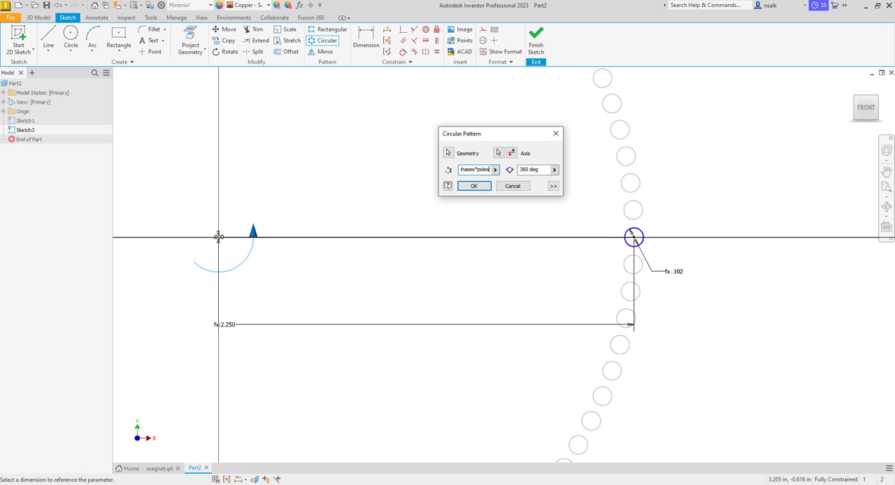
In the below picture I am creating a circular patter circles that I will later extrude to create the copper conductors. I have already defined the diameter of the copper and radius from the center of the machine to the center of the conductor in the xml file. I draw one circle set the dimensions to the predefined parameter list names until the circle is fully defined. Then I click the circular pattern button, click the geometry I would like to repeat (the circle), select the axis of rotation (the origin), and choose the number of circles that I want (this is defined by a mathematical equation using the parameters from the xml file).
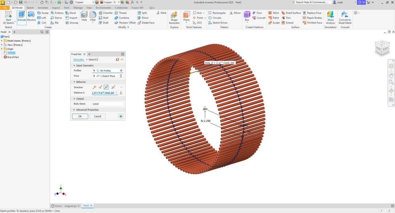
Once the sketch is generated with the full circular pattern, I click the extrude button in the ribbon (or the shortcut "e") and click and drag over the sketch to select all of the circles. I set the extrusion distance to a paramater from the list and choose symmetric extrusion to extrude equal distances about the plane of the sketch (this makes assembly easier), and set the part to copper material.
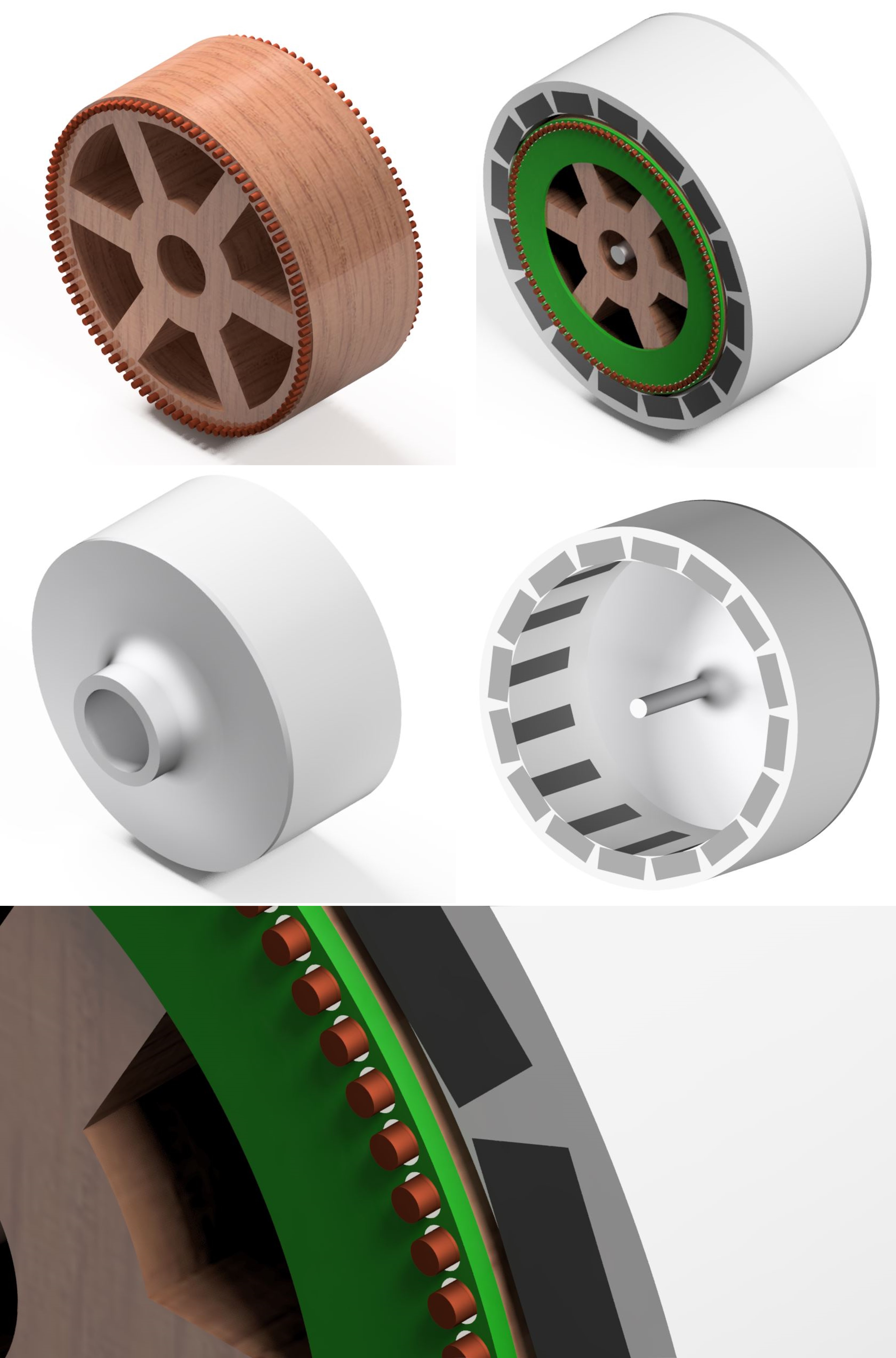
Repeating a similar process for the rest of the parts, considering realistic manufacturing tolerances, available parts from the inventory, and part interconnections. The rendered parts and assemblies are shown in the following figure.
Design files for this week can be found here.