Final Project - Automatic 3-axis 3D Magnetic Field Mapper
Ideation
The final project I have downselected is to create a 3-axis machine that has at the end of it a 3-axis magnetic field probe. The purpose is to validate fields generated by various devices under test, such as permanent magnet rotors or coreless transformers, similar to the manual mechanism used in the paper: "Design and Experimental Analysis of 166 kW Medium-Voltage Medium-Frequency Air-Core Transformer for 1:1-DCX Applications" (Paper). The user be able to set in 3D space the edges of the volume to map manually and then set the voxel size and the machine will the automatically run through the eligible volume and map the field. The previously mentioned paper measures AC fields by measuring voltages induced on 3-coils in different orientations. However, I will be using an IC chip which contains a 3-axis hall-effect sensor which transmits data serially through I2C to a uC. Hall-effect sensors will be only able to realistically measure DC fields (still useful for PM rotor validation), but this end effector can be exchanged in the future.
Mechanisms
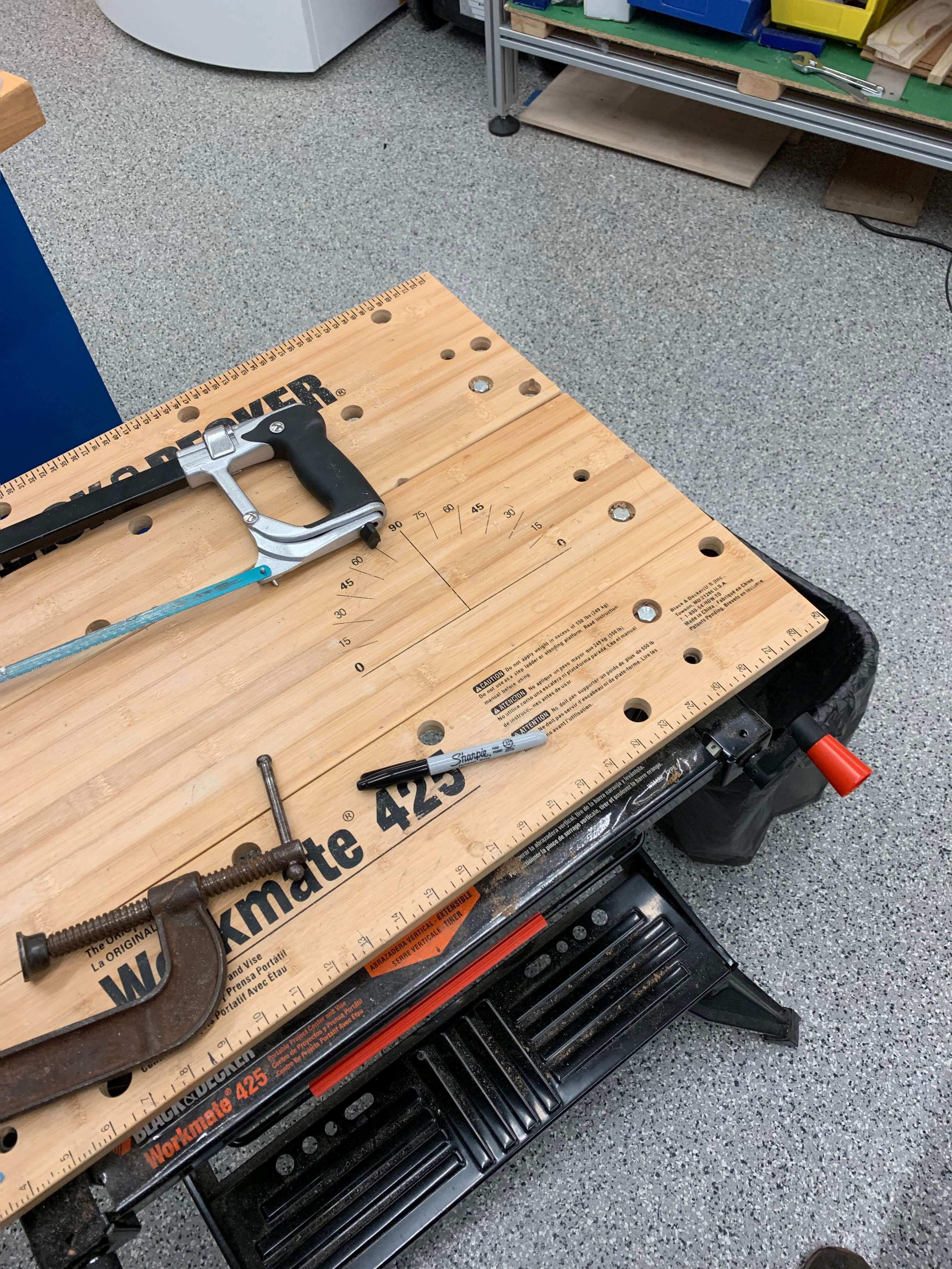
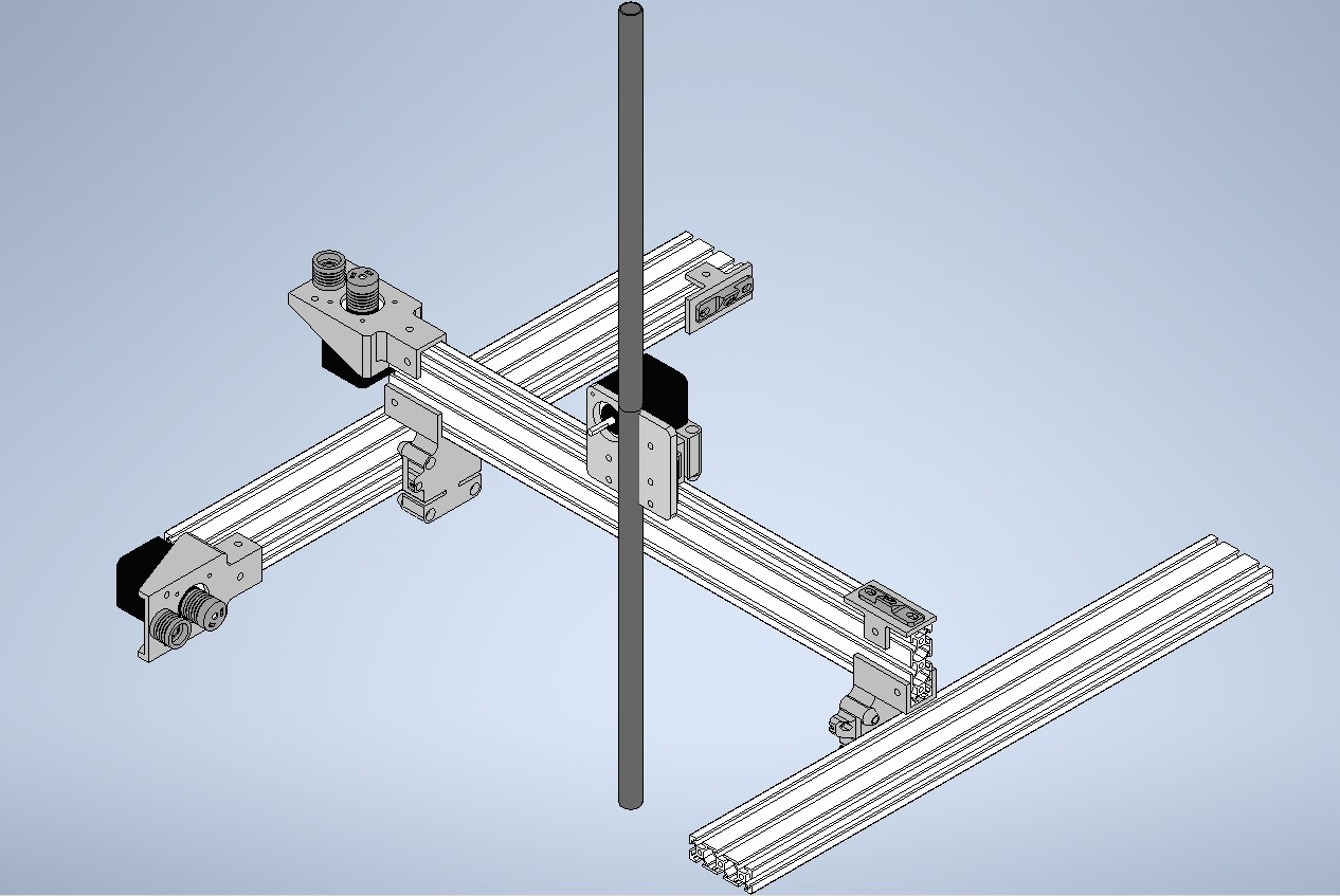
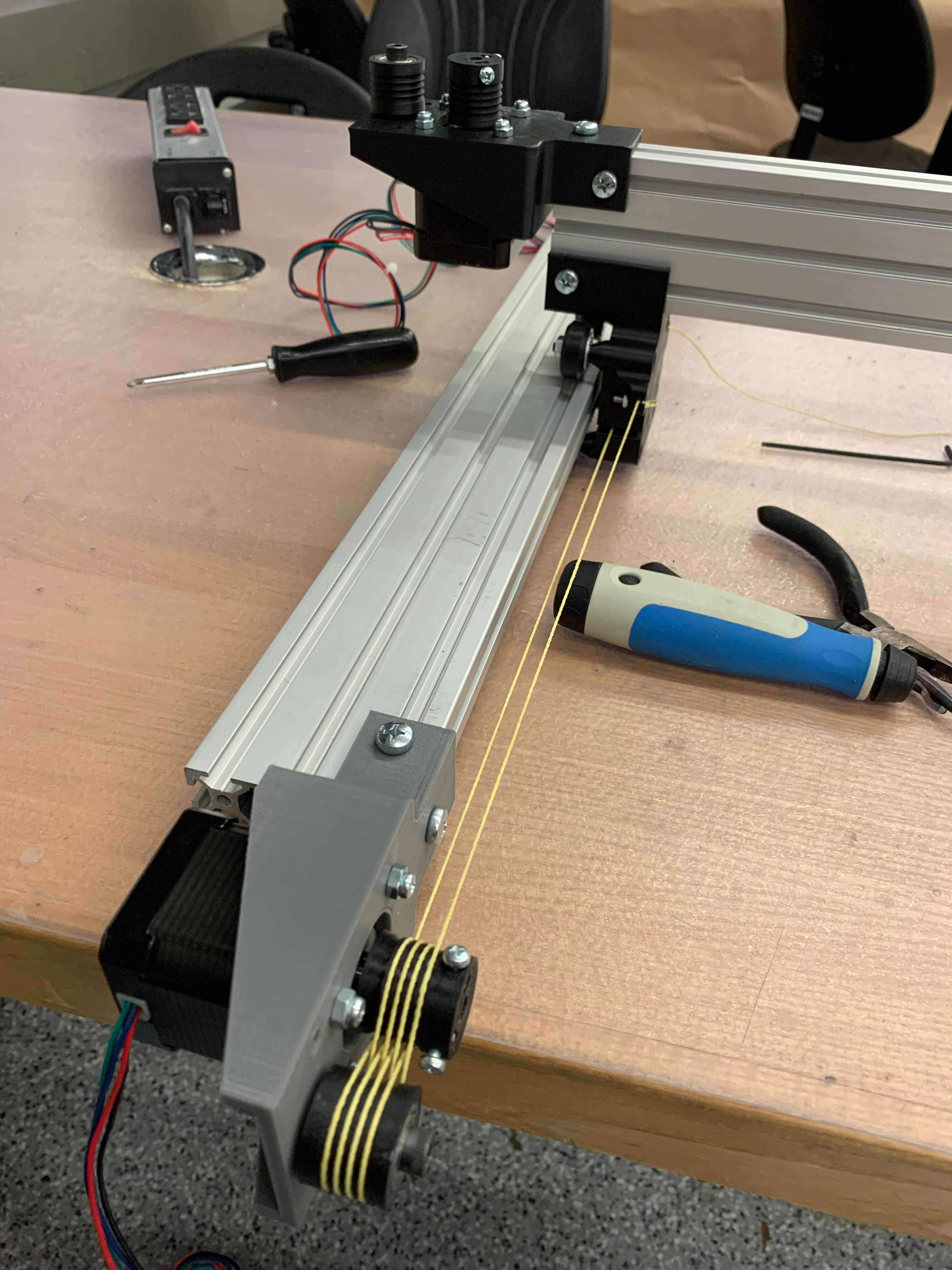
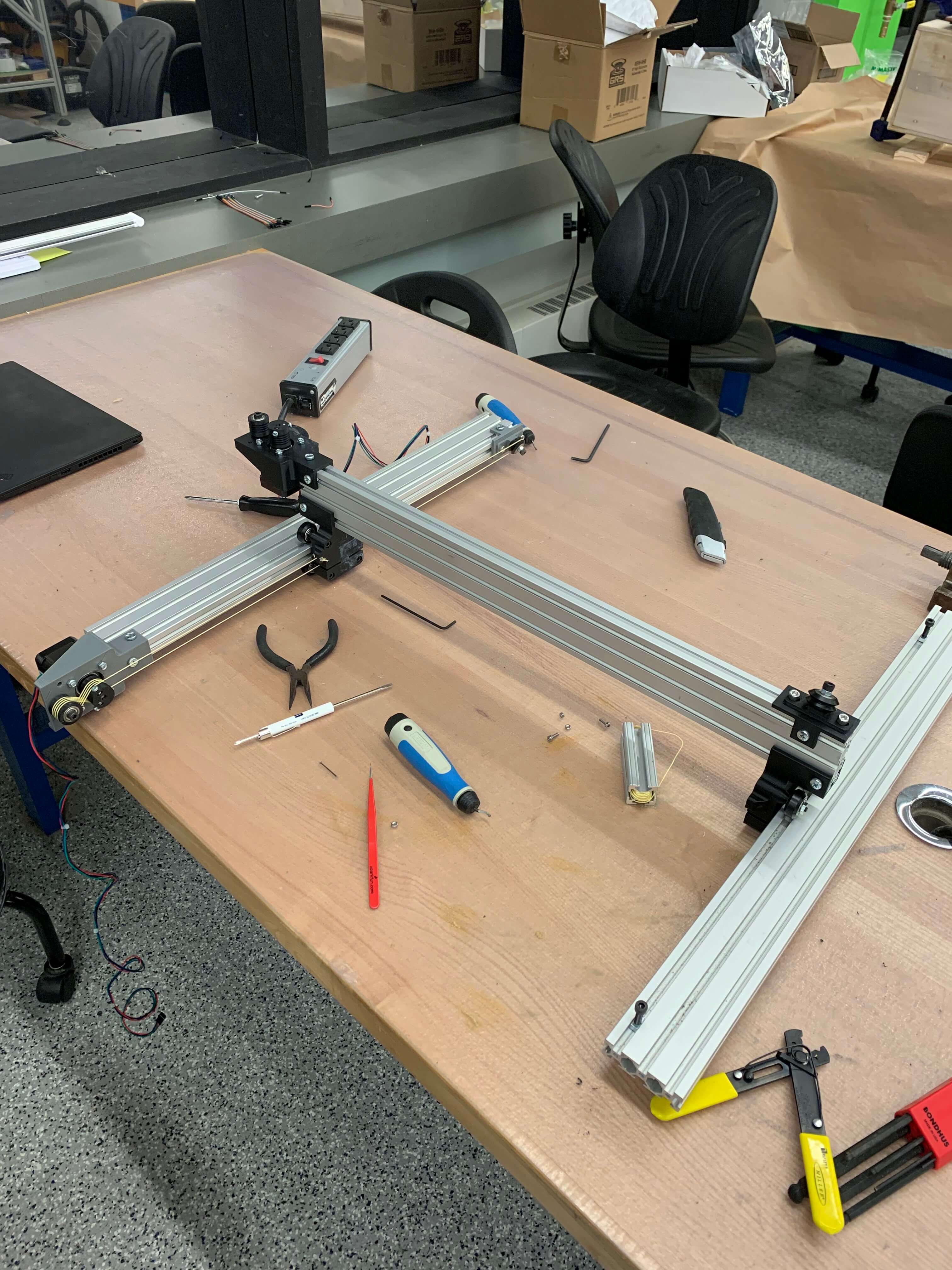
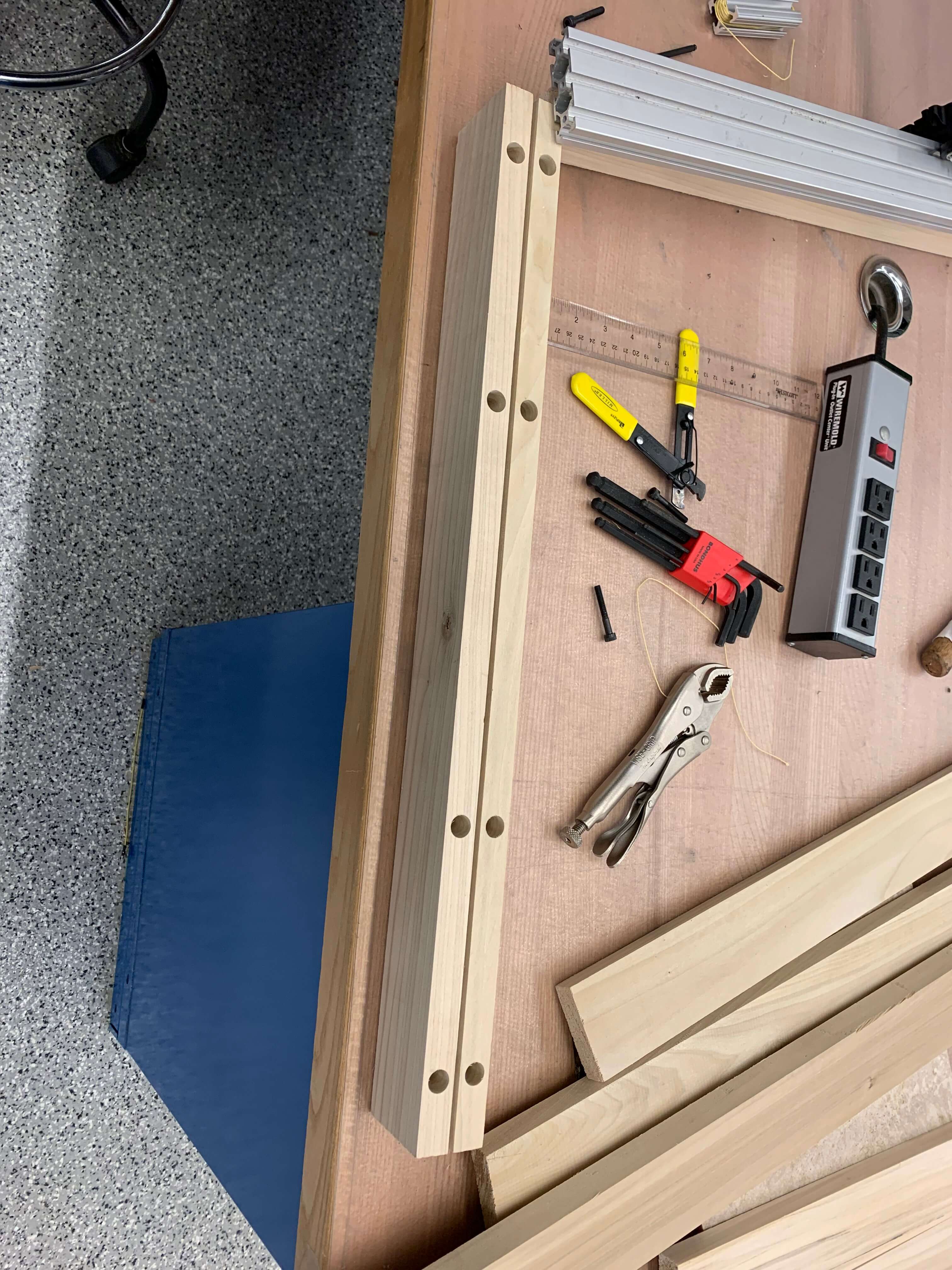
The main machine linear actuator mechanisms were based off a combination of the Urumbu and the Beehive. Since I wanted to be able to fit large DUTs in the probing volume, I selected a nominal linear dimension of 2 ft for the machine lengths. This is another reason for selecting these two mechanisms as reference: the only that changes with increased length is the length of Kevlar string used in the pulley mechanism, which is trivial to increase. For sturdy and well dimensioned components at that length, I chose to use 2060 T-slot Aluminum extrusion. This has the benefit of easily mounting components with T-nuts, as well as the slots acting as rails for Delrin wheels to slide along with minimal friction. In order to cut the Aluminum extrusion to length, I first had to use a handsaw to cut the long extrusion to length that could then be cut on the bandsaw.
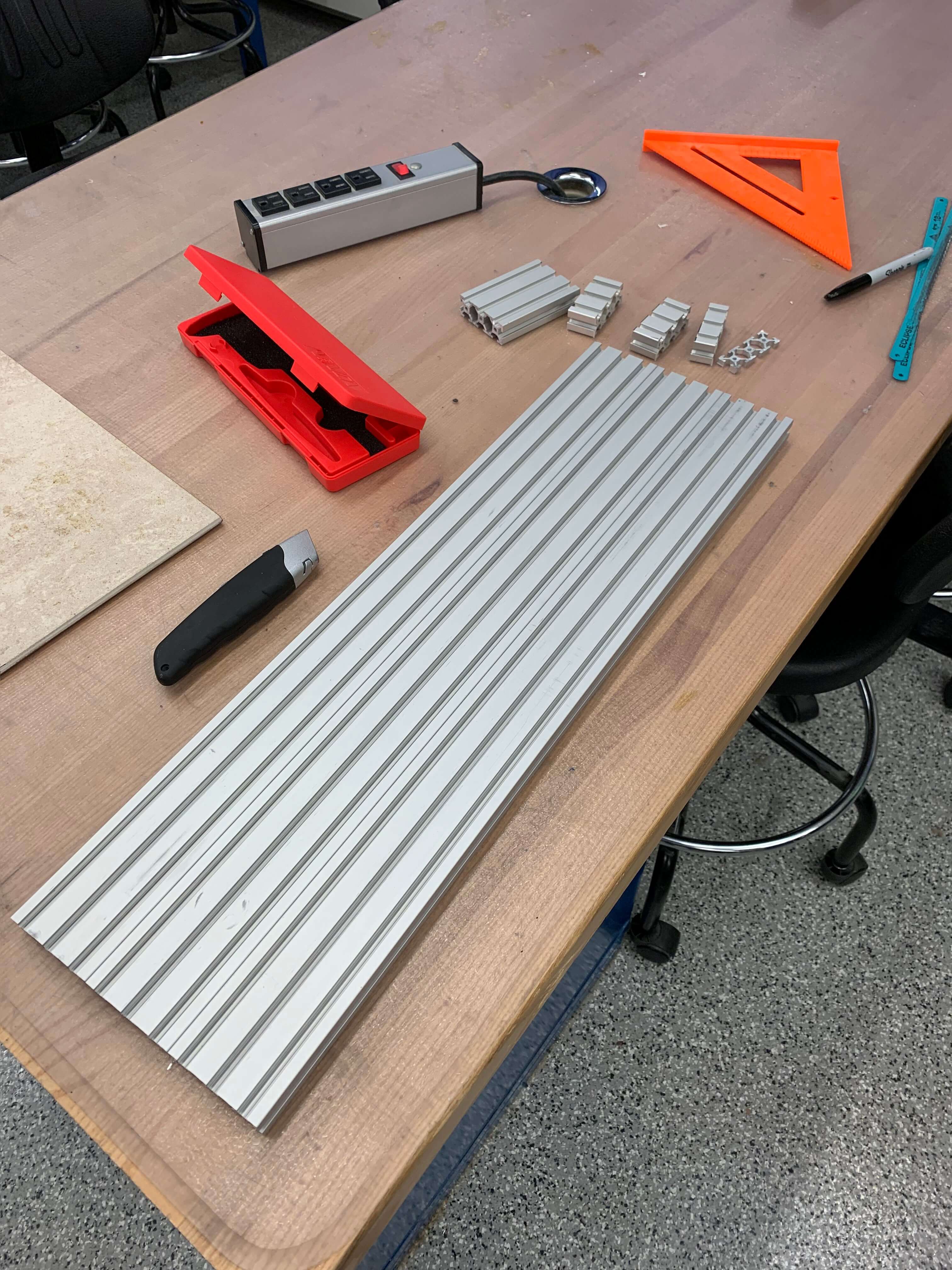
Three segments of the aluminum extrusion were then cut to length at 2 ft each using a bandsaw in order get square edges.
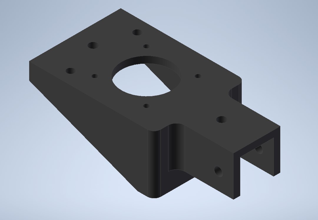
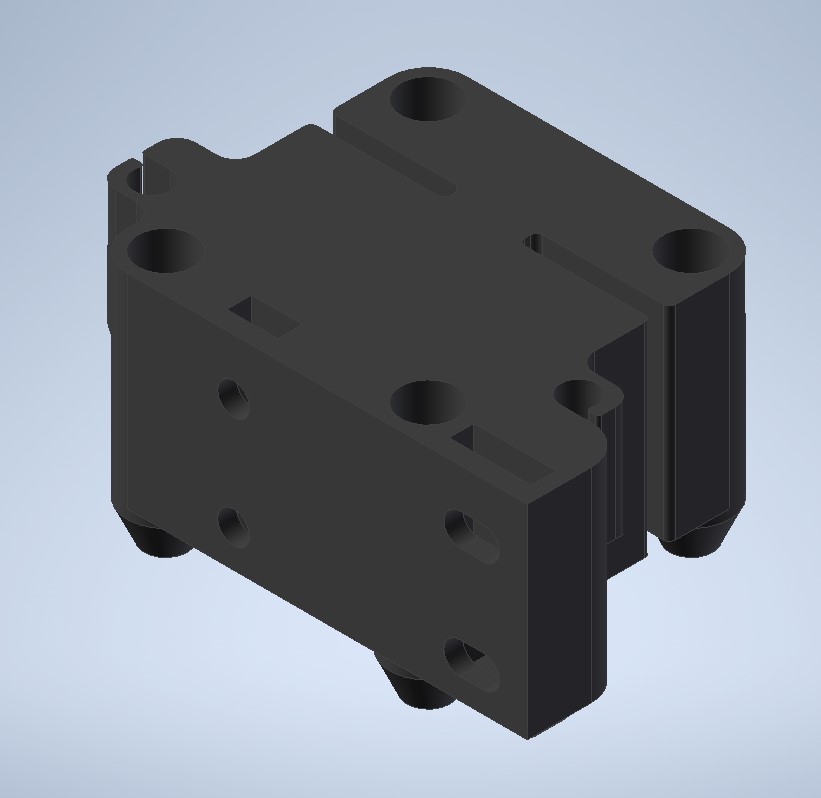
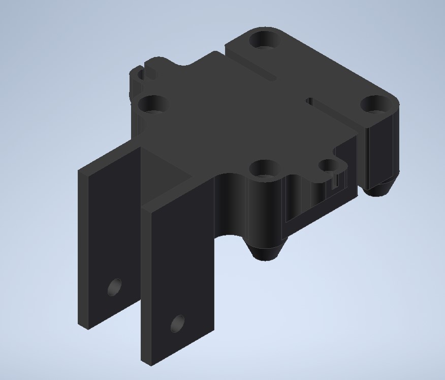
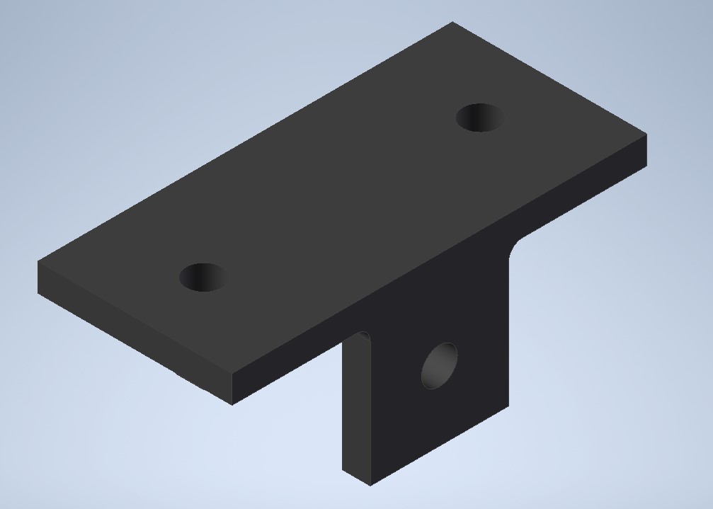
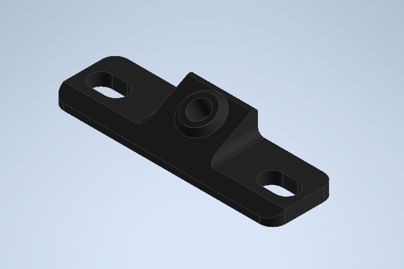
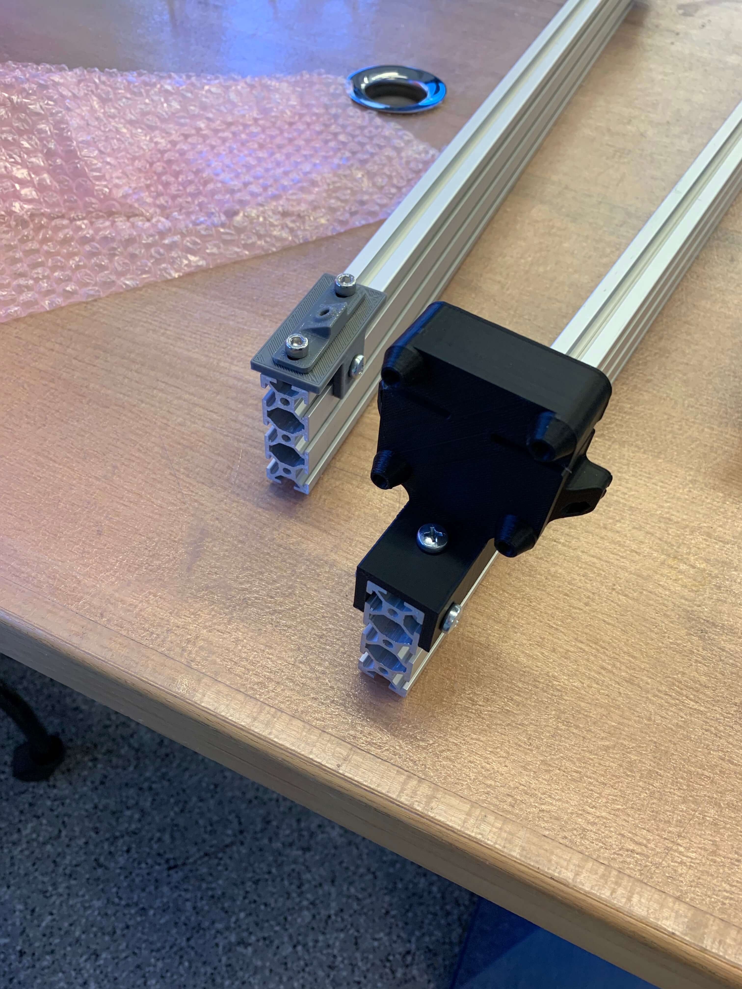
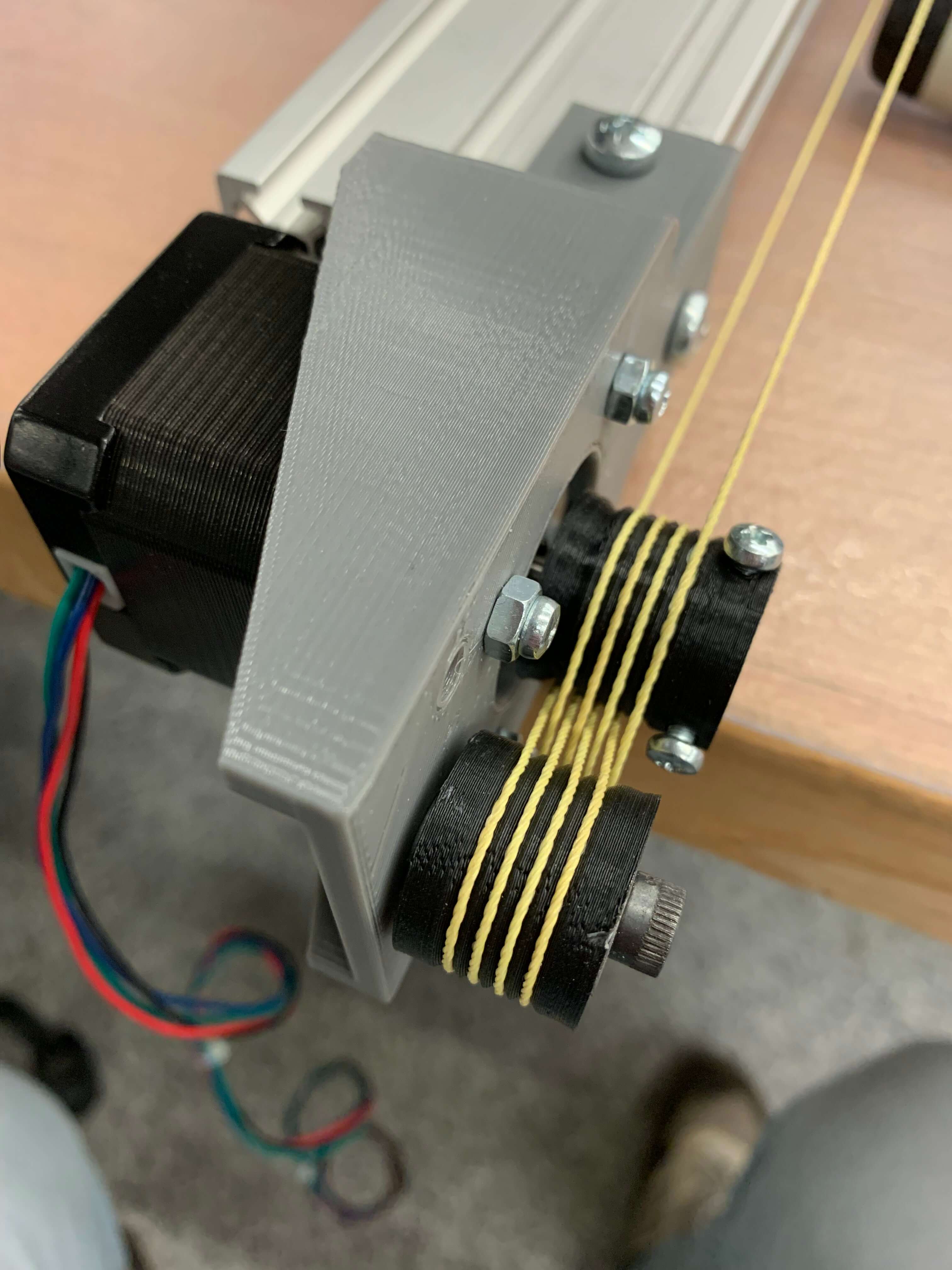
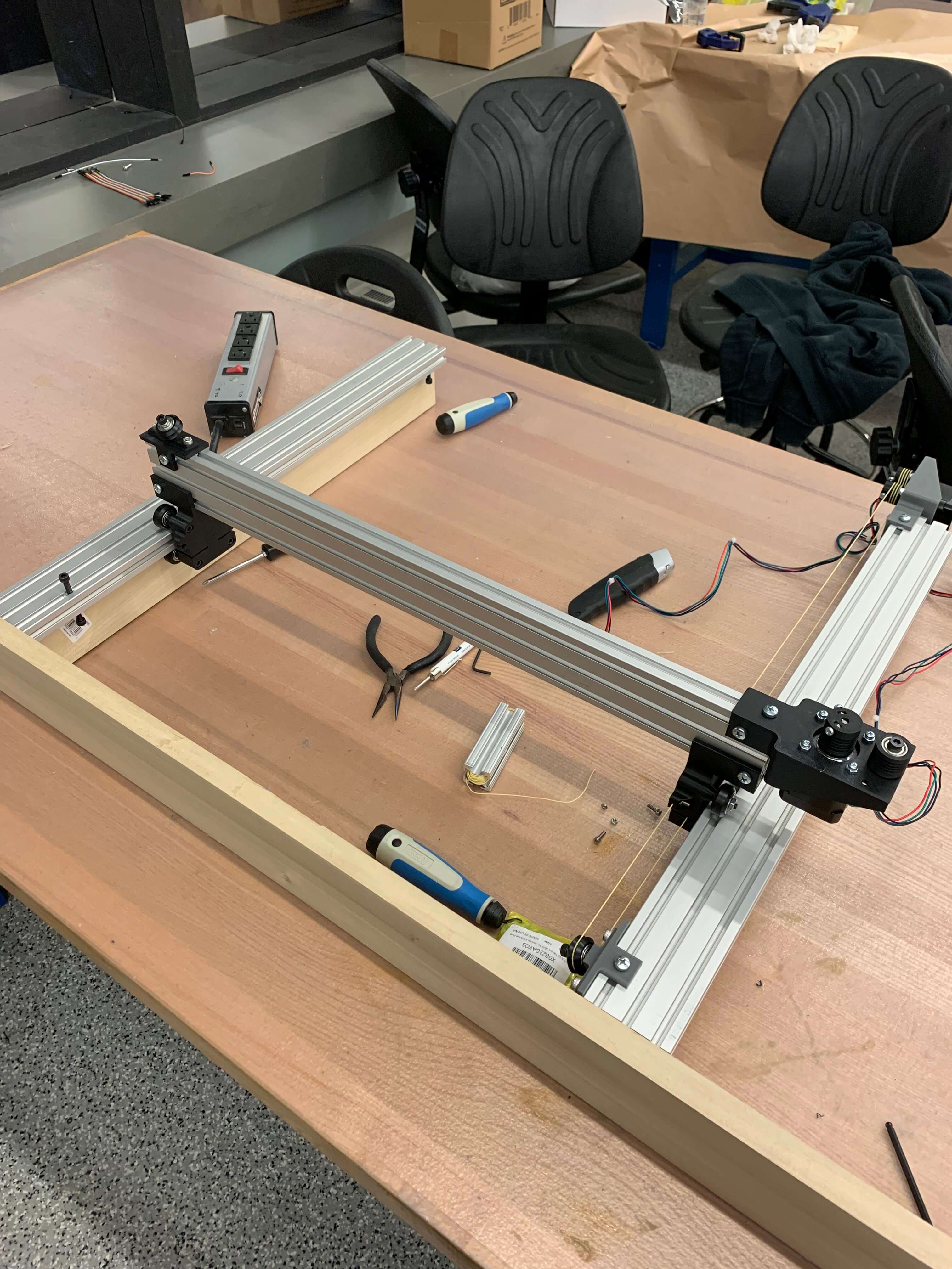
I used the holes and dimensions of the Beehive design as a reference and modified the overall design particular to my own application (I don't need the modular holes of the original Beehive parts). I also liked the flexural mechanism on the carriage which also has a slot in it to hide the return of the kevlar string in the Beehive design. The disadvantage is that the is uses more Delrin wheels than the Urumbu. I also wanted to use the V-slot Delrin wheels as the end pulley, like the Urumbu uses. However, the holding mechanism for the end pulley in the Beehive case has slots for tensioning the Kevlar string, which turns out to be very important; so I kept that part. Below are some snippets of the parts in CAD (design files can be found at the end of this section).
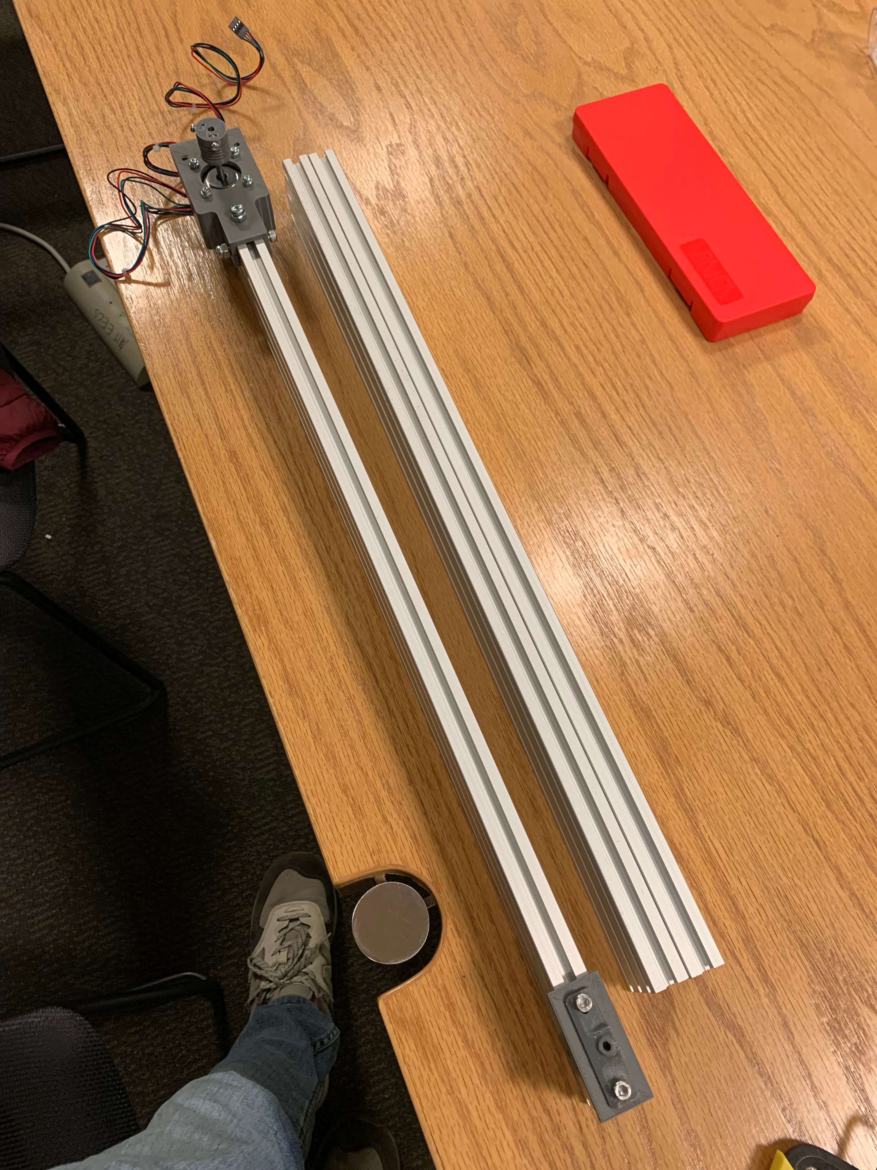
All of the parts were printed on of the two Sindoh 3DWOX 1 printers in EDS. I upped the skin fill and the general fill slightly for structural integrity. I was genuinly suprised with the quality, speed, and surface finish of all of my parts. In addition, the workflow was incredibly simple and I didn't have a single failed print. Before this project, I had been working under the assumption that the Prusa i3 was the best FDM printer in the shop for general parts, but the Prusa i3 experienced many failures and was out of commission most of the semester. Since I'm in the market for a personal 3D printer, this makes me want to buy a Sindoh... Here are some pictures of the parts for the axes mechanisms and them partially assembled to the Aluminum extrusion.
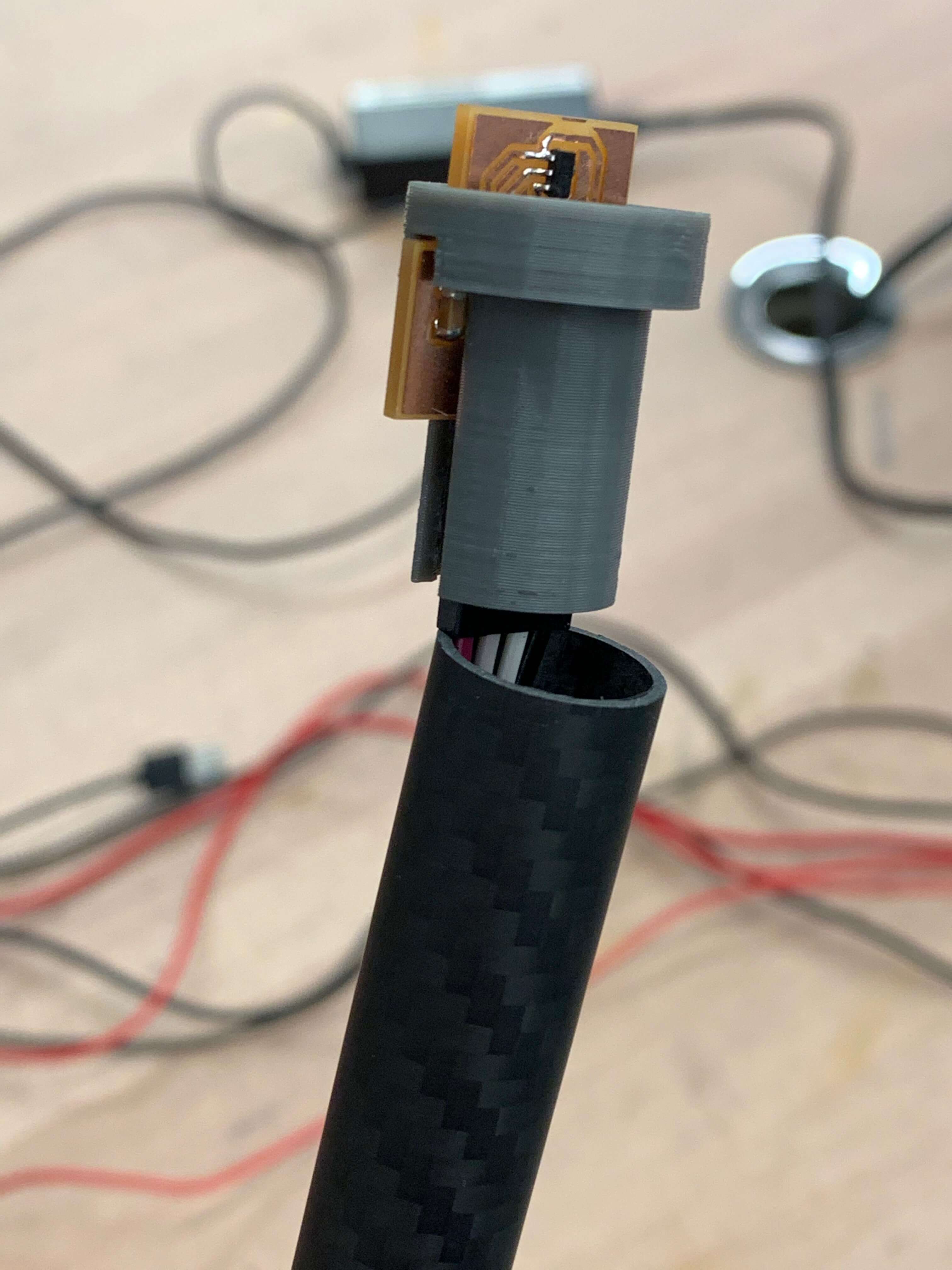
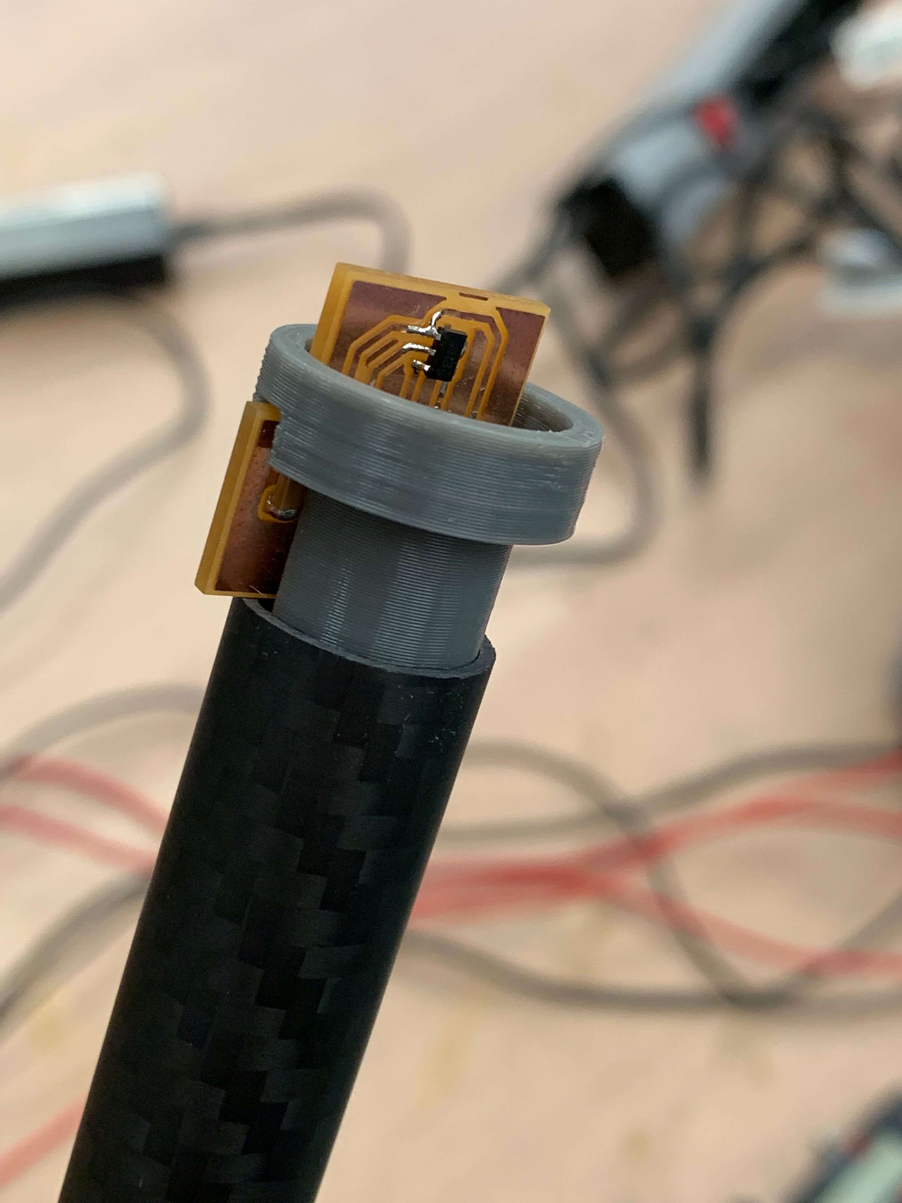
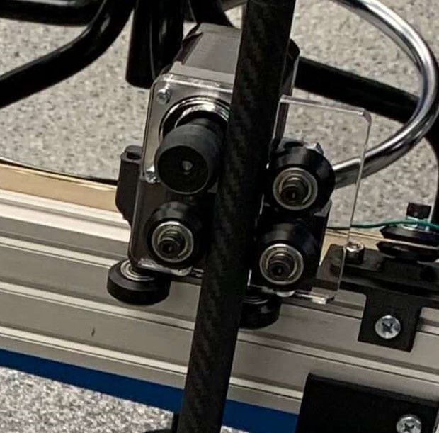
The end effector mechanism was tricky, I wanted a long rod that would move up and down, hold the probe at the tip of it, and route the cables up and away from any DUT in the volume. I also wanted the rod to be non-metallic to avoid impacting the magnetic field in the domain. I ended up purchasing some carbon fiber tubing that would fit all of these descriptions. To move the tube up and down I decided to use the V-slot delrin wheels to constain the rod in all axes, while one would be actuated with a stepper motor. The tricky part is to get enough grip and tension on the rod and prevent it from slipping or rotating. I decided to laser cut some thick acrylic and mount it on the end-effector carriage. One piece would mount the stepper motor and a v-slot wheel to the carriage, and the other piece would just have to v-slot wheels that would be able to move within a slot and be tightened against the rod to prevent slippage.
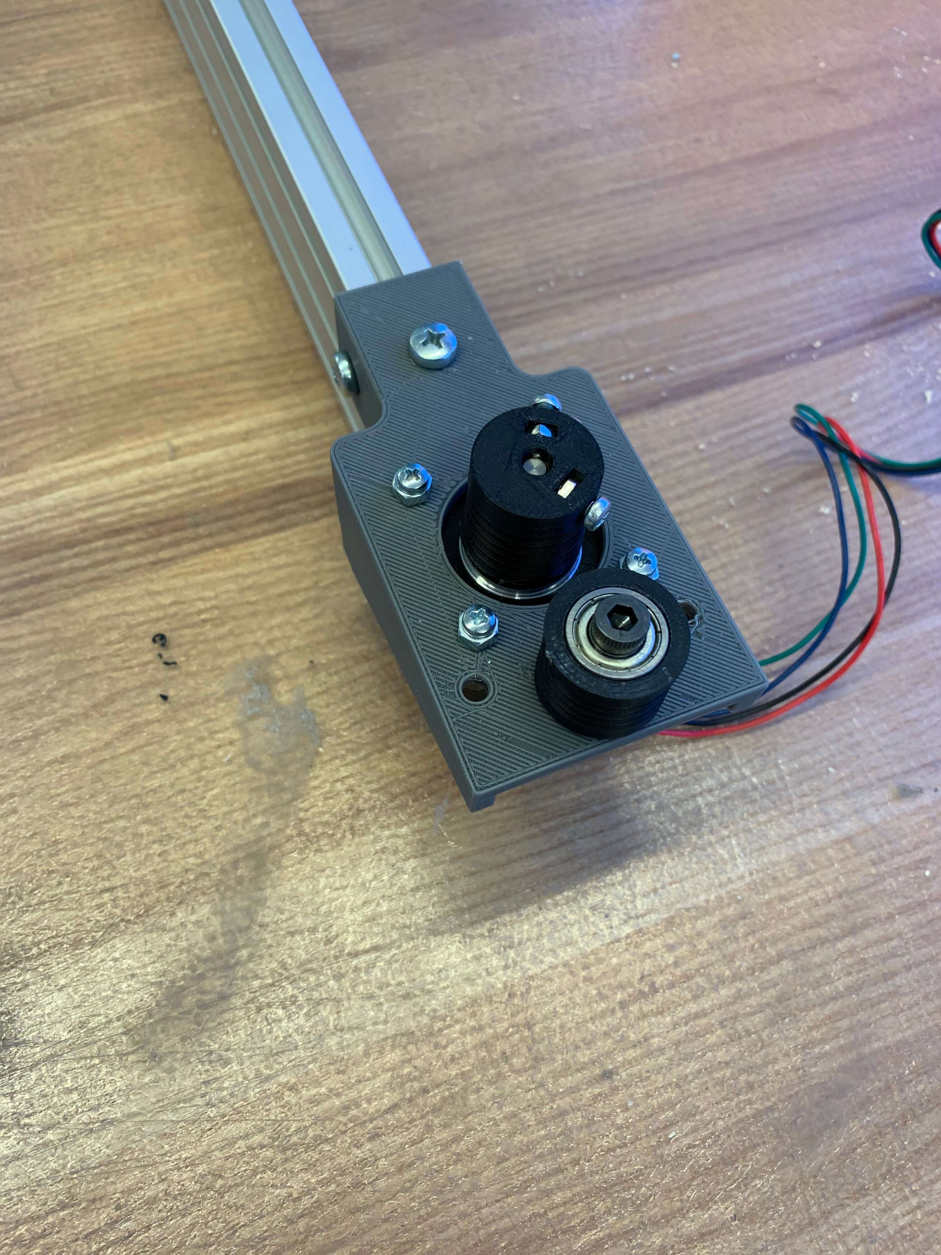
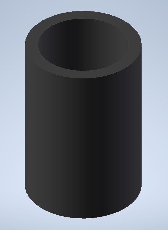
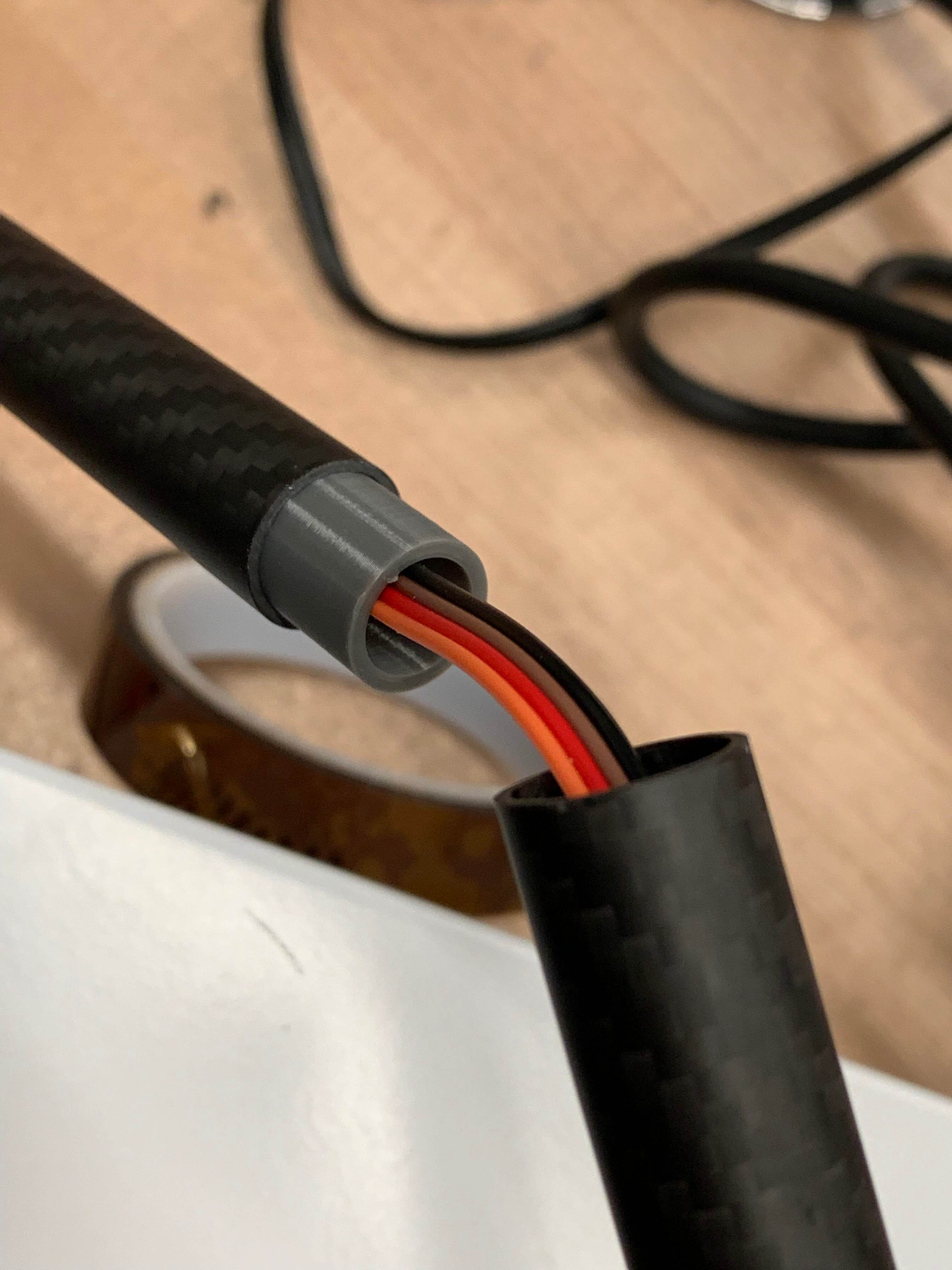
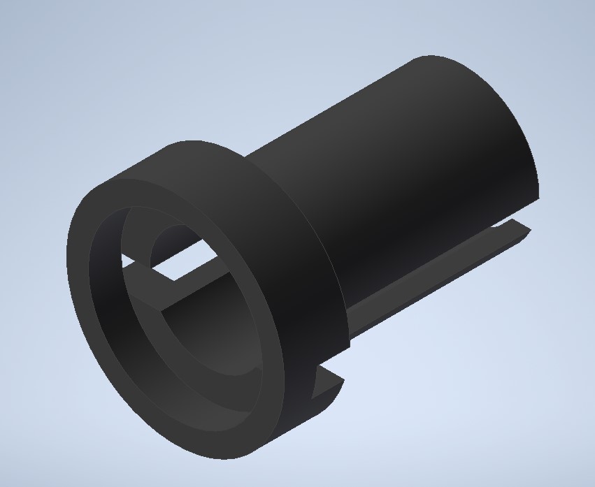
Since the tubing I purchased was not long enough for what I wanted, I need to connect two identical pieces together, I printed a simple plug that would press fit to create the connection with the need for glue and allow cable to run though it still. I also printed a probe holder that similarly press fits into the end of the tubing and holds the probe in place. Finally, I needed to print a replica of the V-slot delrin wheels that could be attached to the shaft of the stepper motor with set screws (this part didn't have enough grip, so I had to cut and mold a heat shrink over it to get some of that grip).
Heres a link to download all of the mechanism design files.
Electronics
Most of the electronics for this project were developed in past weeks. The electronics consist of a main controller board (which will be explained in further depth here), three stepper driver boards (see Output Devices), and a probe board which contains the 3D hall-effect sensor (see Input Devices).
The main controller board communicates serially with a computer via micro USB, sends step pulses to the three stepper boards (plus direction flags), and reads communicates with the TLE493d TLE493d magentic field sensor to relay measurements back to the computer. Below is a KiCAD schematic and PCB layout for the board.
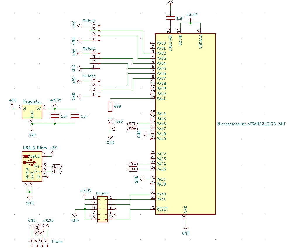
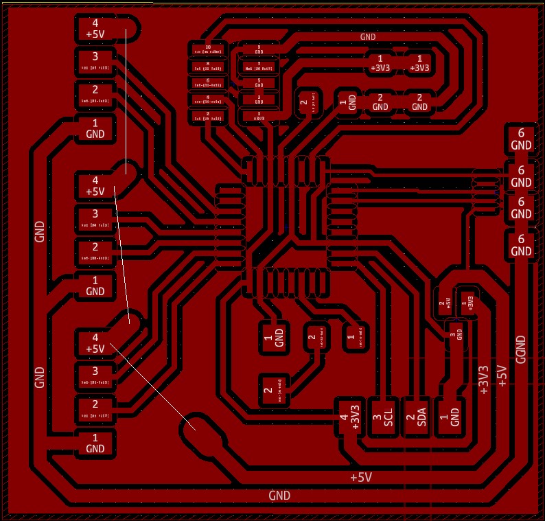
The SAMD21E18A was used due to the number of pins available. I needed 2 pins cable of I2C communication with the field sensor, and two pins per motor (one for step pulsing and one for a direction flag). The entire function of the controller is to listen for a command given serially from the computer and to send out pulses to the various stepper driver boards. Once the pulses are all sent out (in open loop), it waits a fraction of a second and reads the field sensor and sends it back to the computer serially. Here is the code for the main controller board.
#include <Tle493d_a2b6.h>

Tle493d_a2b6 Tle493dMagnetic3DSensor = Tle493d_a2b6(Tle493d::FASTMODE,Tle493d::TLE493D_A0);

#define XPOS 2
#define XNEG 3
#define YPOS 4
#define YNEG 5
#define ZPOS 6
#define ZNEG 7
#define LED 11

int T = 30000; // number of micro seconds delay (minimum is 5000)

int xstep = 0;
int ystep = 0;
int zstep = 0;

int XPIN;
int YPIN;
int ZPIN;

long max3(long a, long b, long c){
   long maxguess;
   maxguess = max(a,b);
   maxguess = max(maxguess,c);
   return(maxguess);
}

void setup() {
  Serial.begin(9600); // opens serial port, sets data rate to 9600 bps
  while(!Serial);

  pinMode(XPOS,OUTPUT);
  pinMode(XNEG,OUTPUT);
  pinMode(YPOS,OUTPUT);
  pinMode(YNEG,OUTPUT);
  pinMode(ZPOS,OUTPUT);
  pinMode(ZNEG,OUTPUT);
  digitalWriteFast(XPOS,LOW);
  digitalWriteFast(XNEG,LOW);
  digitalWriteFast(YPOS,LOW);
  digitalWriteFast(YNEG,LOW);
  digitalWriteFast(ZPOS,LOW);
  digitalWriteFast(ZNEG,LOW);

  Tle493dMagnetic3DSensor.begin();
  Tle493dMagnetic3DSensor.enableTemp();

  pinMode(LED,OUTPUT);
  digitalWriteFast(LED,LOW);
}

void loop() {
  if (Serial.available() > 0) {
    digitalWriteFast(LED,HIGH);
    xstep = Serial.parseInt();
    ystep = Serial.parseInt();
    zstep = Serial.parseInt();
    XPIN = XPOS;
    YPIN = YPOS;
    ZPIN = ZPOS;
    if(xstep<0){
      XPIN = XNEG;
      xstep = -xstep;
    }
    if(ystep<0){
      YPIN = YNEG;
      ystep = -ystep;
    }
    if(zstep<0){
      ZPIN = ZNEG;
      zstep = -zstep;
    }
    long maxcnt = max3(xstep,ystep,zstep);
    for (uint32_t cnt = 0; cnt < maxcnt; ++cnt) {
      if(cnt<xstep)
        digitalWriteFast(XPIN,HIGH);
      if(cnt<ystep)
        digitalWriteFast(YPIN,HIGH);
      if(cnt<zstep)
        digitalWriteFast(ZPIN,HIGH);
      delayMicroseconds(T/2);
      digitalWriteFast(XPOS,LOW);
      digitalWriteFast(XNEG,LOW);
      digitalWriteFast(YPOS,LOW);
      digitalWriteFast(YNEG,LOW);
      digitalWriteFast(ZPOS,LOW);
      digitalWriteFast(ZNEG,LOW);
      delayMicroseconds(T/2);
    }
    delayMicroseconds(2*T);

    Tle493dMagnetic3DSensor.updateData();
    Serial.print(Tle493dMagnetic3DSensor.getX());
    Serial.print(",");
    Serial.print(Tle493dMagnetic3DSensor.getY());
    Serial.print(",");
    Serial.println(Tle493dMagnetic3DSensor.getZ());
    digitalWriteFast(LED,LOW);
  }
}
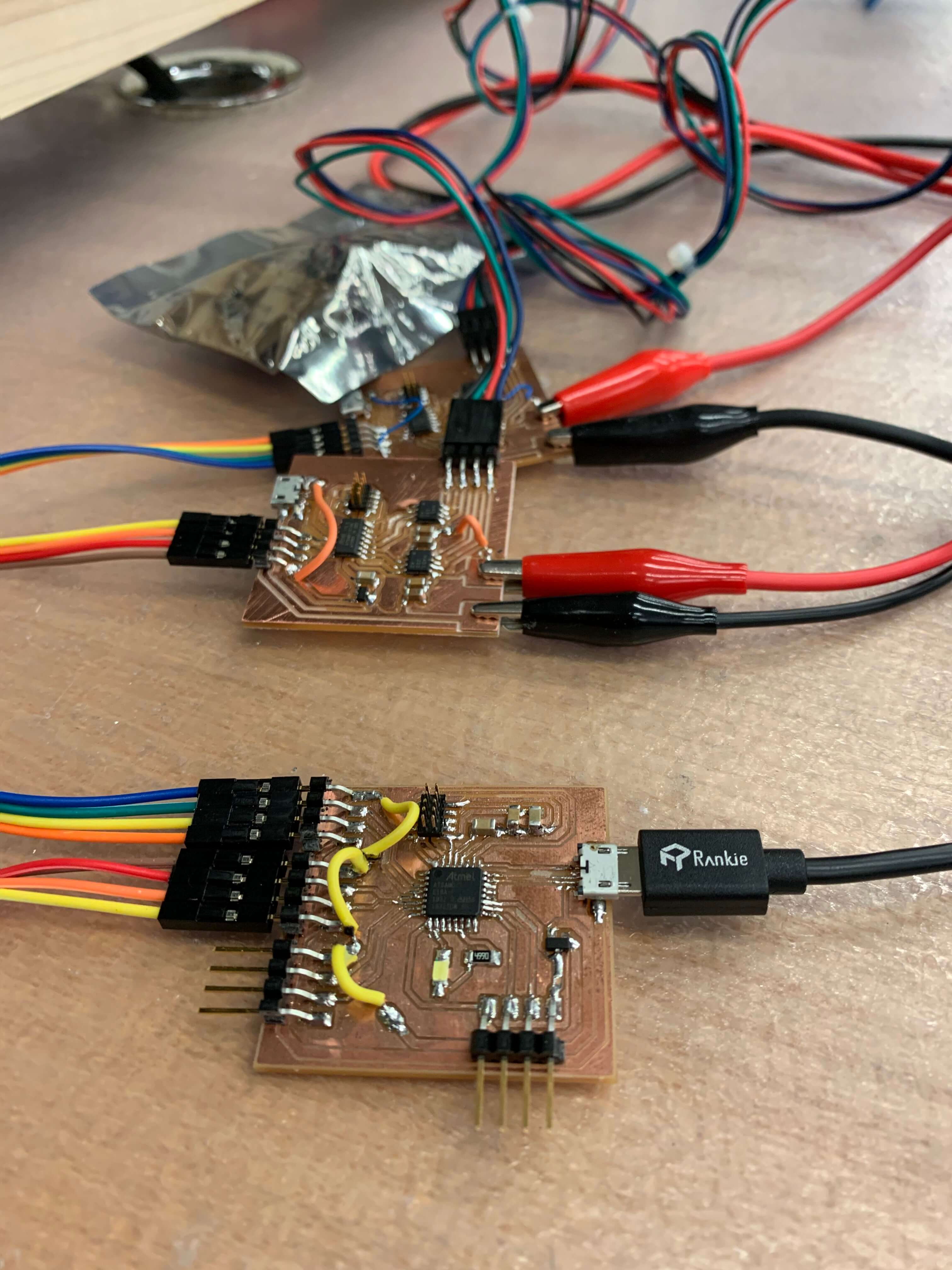
Here's an image of the main controller hooked up to two stepper driver boards for testing. All of the design files for the electronics and code can be downloaded here.
Structures
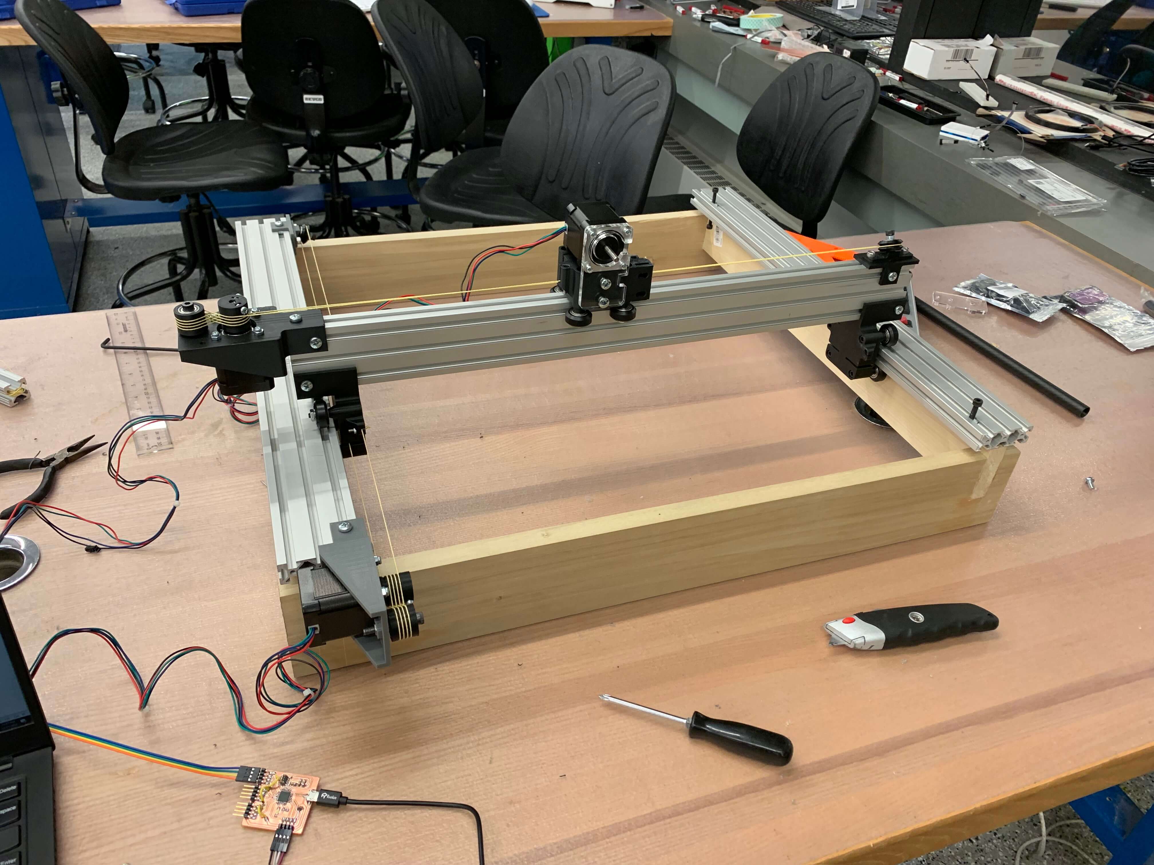
With the main 3-axes mechanism built, it can be mounted to any structure that raises it up off the ground. Because I want to limit the amount of metal in my field mapper in order to limit the impact of eddy currents on the field distribution and reduce costs, I decided to build the structure out of Poplar wood. I purchased 20 boards with dimensions of 3/4" x 2.5" x 24" from Home Depot for a total of $40. Into the side of two of these boards, I used a mill to drill straight through at 4 points with a 5 mm diameter bit (for M5 machine screws).
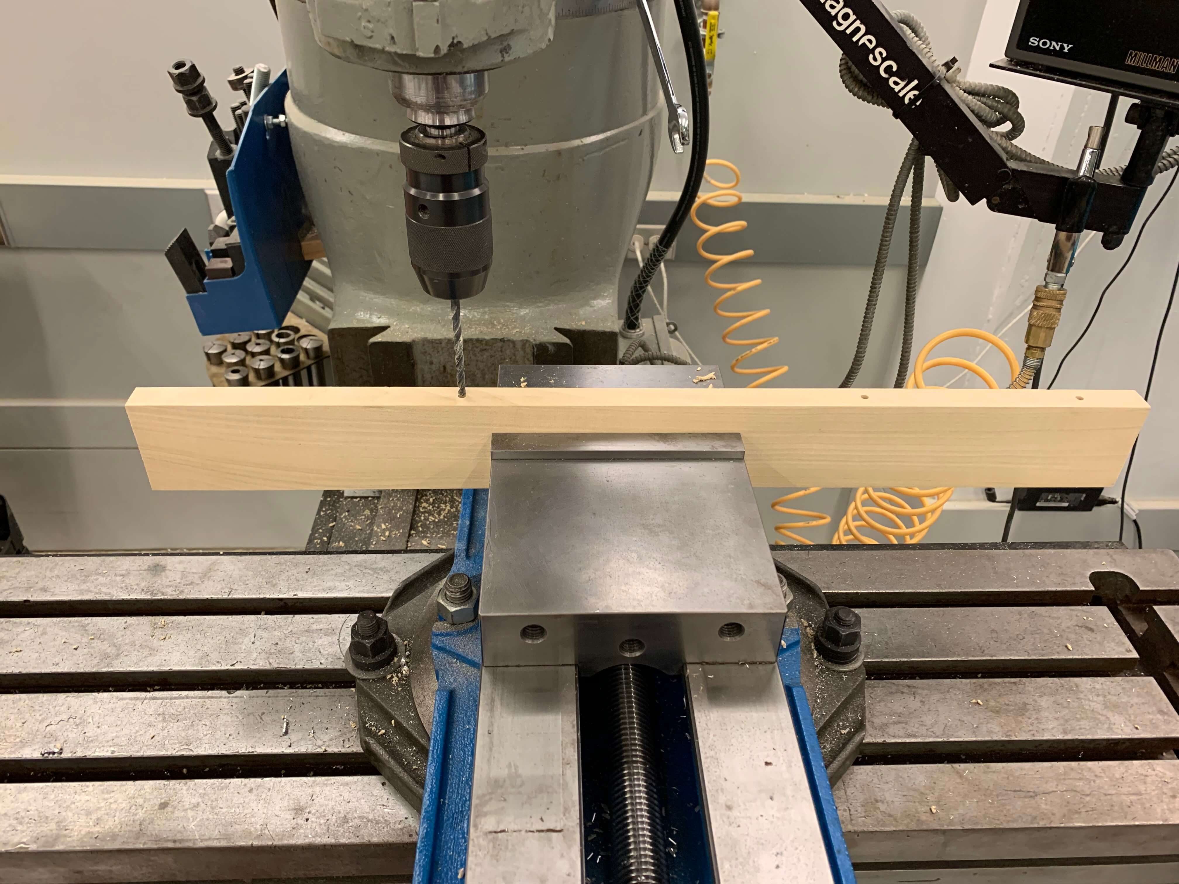
I then used an end mill to put a quarter inch hole at each of these points about 1.75" deep.
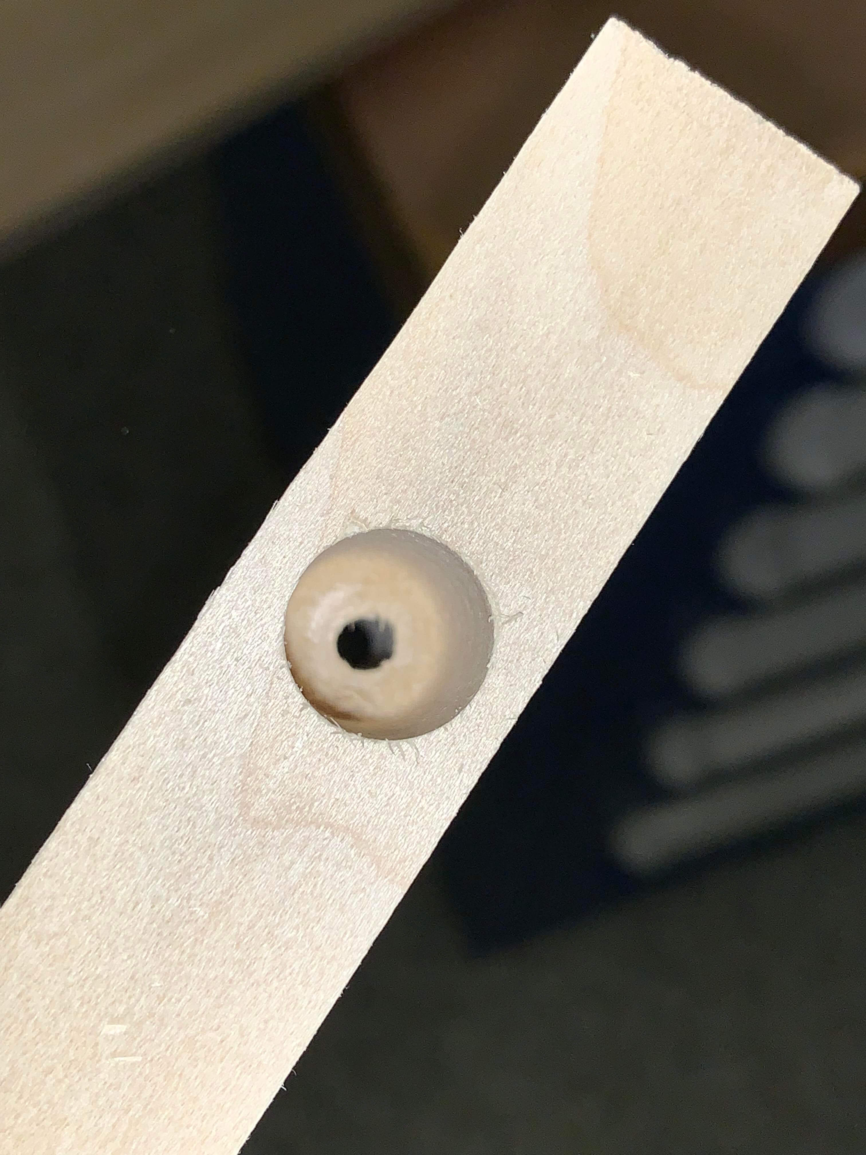
I then mounted these to the two side rails using T-nuts. The machine screws are hidden in the larger slots.
This raises any mounting components away from the linear actuators mechanisms. In order to constrain the two side rails from rotation and fix their distance besides the roller carriages, two additional cross beams were slotted with a band saw, flattened using a dremel, and finished with a file. This was done on a 3/4" x 3.5" x 6' poplar board that was cut to length (roughly 2 feet). I then used wood glue to bond the slotted board to the two rail boards, making them flush.
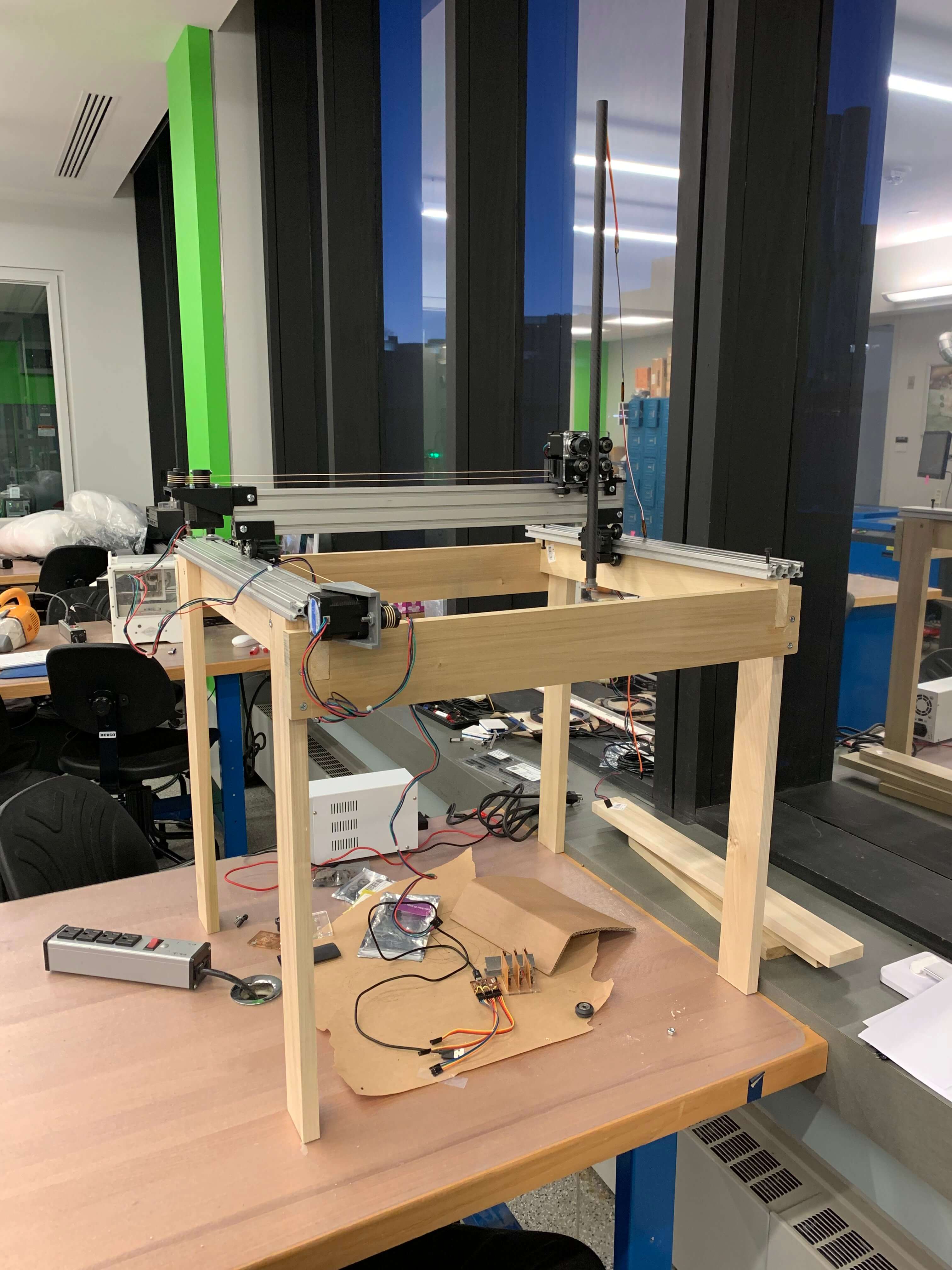
I later took this whole assembly and mounted it on "stilts" composed of 4 of the smaller Poplar 2' planks. These were first glued and then fastened further with screws because they are load bearing joints.
Graphic User Interface
Since I've never coded in Javascript and I am quite proficient in MATLAB, having built a GUI in MATLAB in the past as well as having received the Mathworks fellowship for the past two years, I decided to use MATLAB to build my GUI. The app builder allows you to build a structure for you app by clicking and dragging. Once this template is generated I export it to a .m file and edit it with my own custom code that does the magic. MATLAB has a serialport function (previously described in Interface & Application Programming) which also me to communicate with the main controller board which is all I need. Most of the computation happens on the computer and then the number of steps in each direction are sent to the main controller board via serial. The GUI waits to receive data back from the main controller before proceeding. Below shows the general layout of the built application.
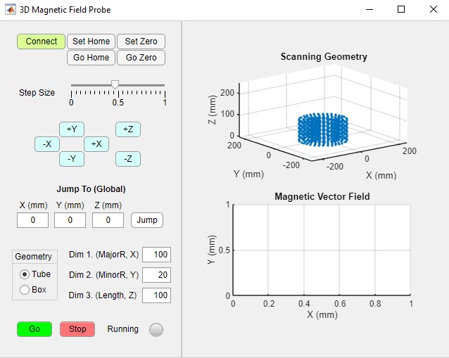
Breaking down the GUI features one by one. The connect button is pressed and inititates a connection to the main controller, generating a serialport object. If you click this button and it unclicks itself, a connection to the board was not made (most likely not plugged in). There are two defined points in the domain: the zero location and the home location. These are both initialized to the points at which the machine starts when it's turned on. After that the user can set both points and also instantaneously jump to those points. The zero point acts as the origin for the geometry which will be scanned. The home location is a point which the machine can safely go to and rest (it will first raise the Z and then travel in XY to the location to avoid collisions with geometry. The user can also select a relative step size using the slider. This changes the step size from 1 to 80. and is normalized to the maximum of 80 steps. It also determine how find the probe points are in the geometry. A larger value means the points are spaced further apart.
Using the blue XYZ buttons, the user can manually move the machine in any of the three axes. Here the step size slider determines how far to go when the buttons are clicked. This is used to set the home and zero points in space. There's also a jump to button with absolute coordinates. I don't use this very much and it would be helpful if it were relative to the zero point. Eventually though I will have the shutdown routine return the machine to home before turning off so that when the machine is turned back on home is always set to the origin and the absolute coordinates mean something. Finally, the important part of selecting the plotting domain. Two choices are available: a box or a tube. The user can select which one they would like to plot and enter the dimensions. The three dimensions (all in mm) that may be edited mean different things for each geometry. For the tube, the dimensions are major radius, minor radius, and height. For the box, the dimensions are width (X), depth (Y), and height (Z). Once the user selects "Go" the probe will move to the zero location and then begin the probing sequence. The top figure in the GUI shows the points that will be probed and the user can set the slider to vary the fidelity of the geometry. The "Stop" button can be hit at any time and will stop the probing and plot the data points that have been measured up until that point.
The MATLAB code for the GUI can be downloaded here.
Integration and Packaging
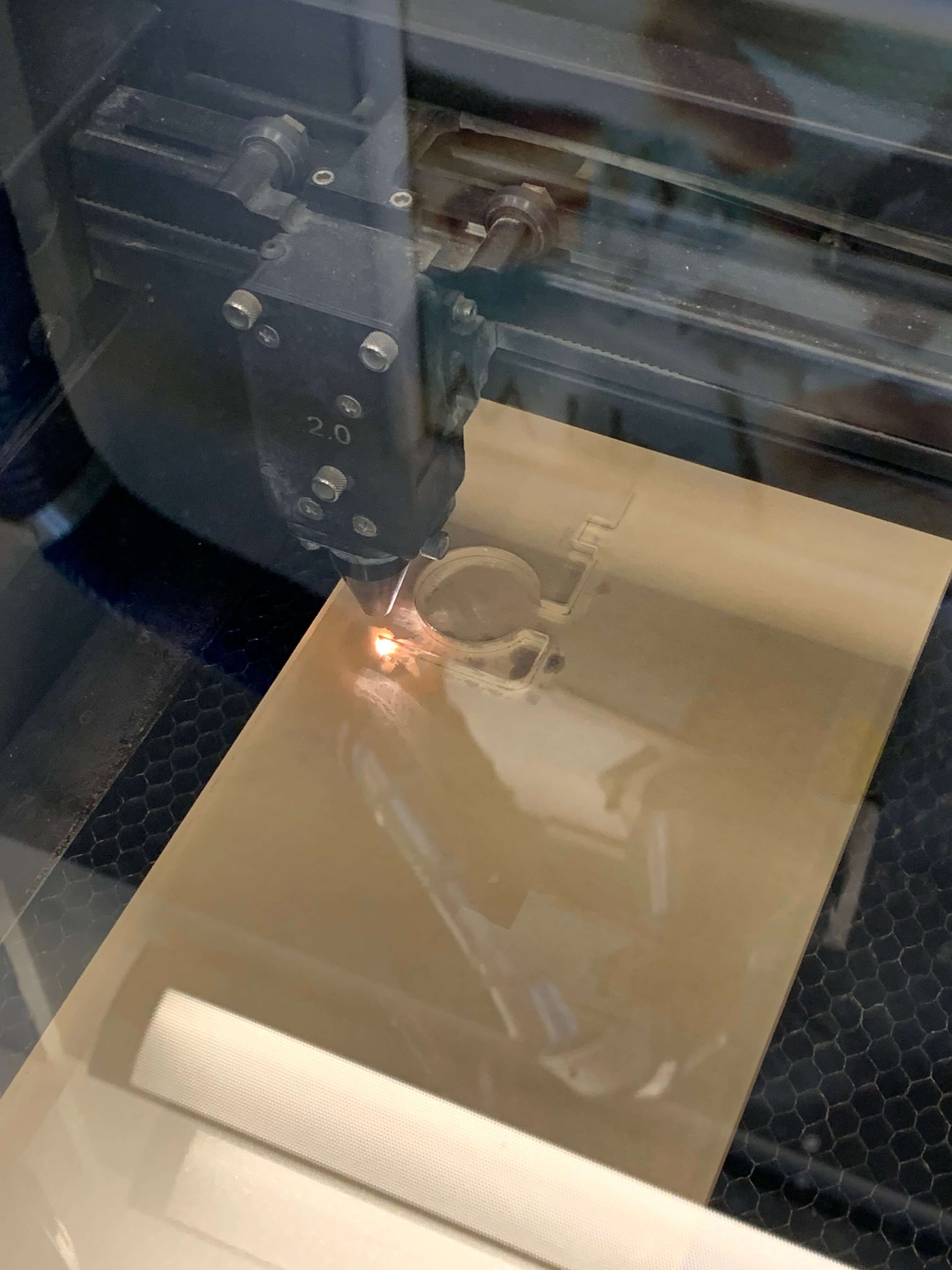
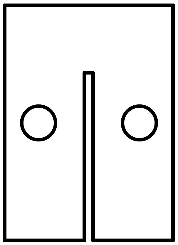
Outside of creating the wooden structure that raises the machine, the only packaging comes in the form of mouning the electronics to the machine. To do this, I decided to laser cut some thin acrylic with slots equal to the dimensions and thickness of my PCBs. The PCBs will be press fit into the slots and there will be holes in the acrylic for driving screws through into the wood. The first piece I made was to hold the three driver boards in an array. See the outline for this piece below.
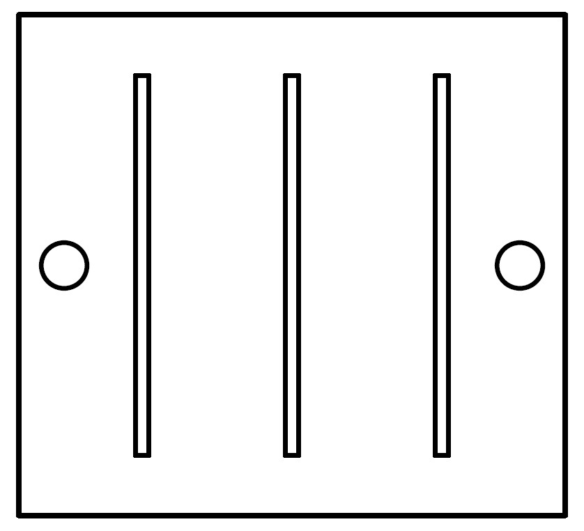
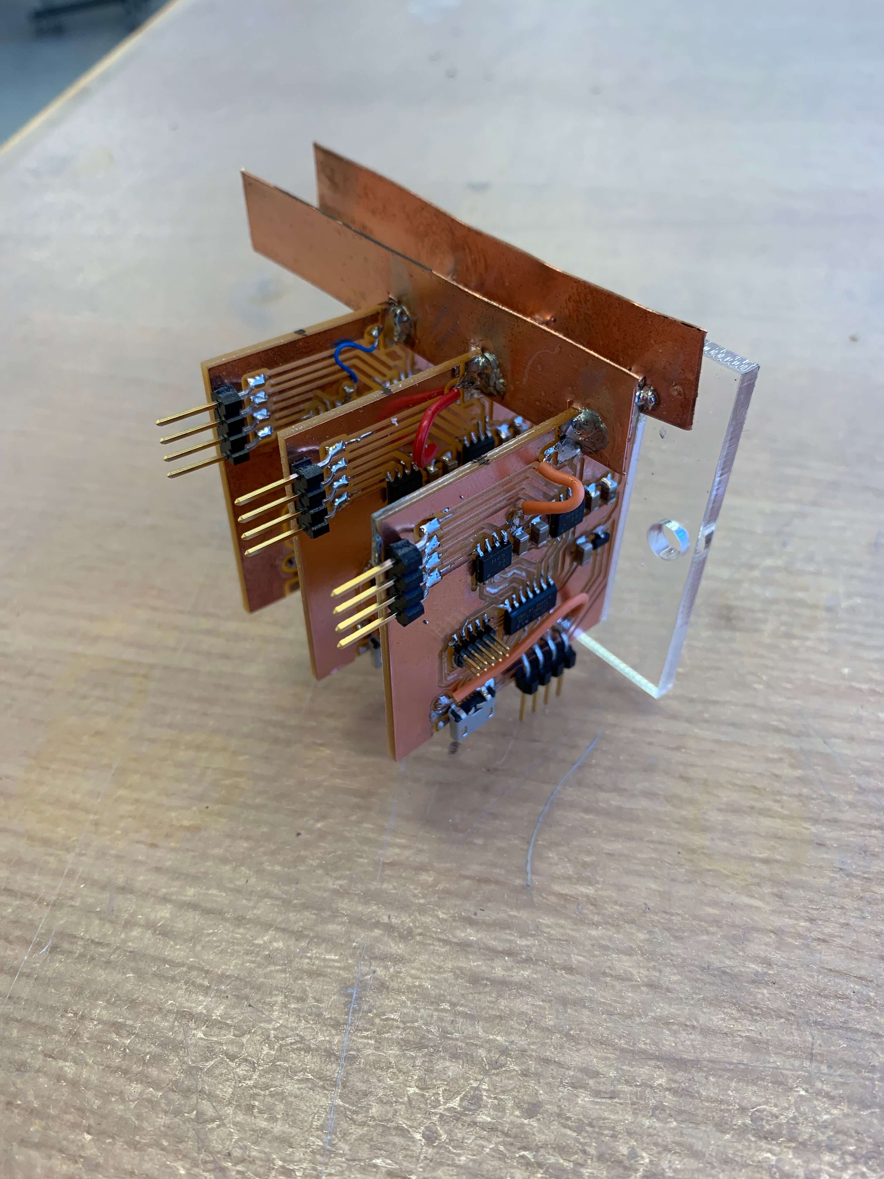
Neil made a comment in one of the lectures about how the laser cutter is the most overused piece of equipment. While that may be true, the ability to cut precise dimensions from a hard, structural materials such as acrylic in less than 5 minutes, including the overall workflow, is so valuable. It's the quickness that makes it so useful especially for prototyping and iteration. I cut 2-3 of these driver holders before I found the right thickness to hold the boards together and the whole thing to look less than 15 minutes. Here's a picture of the driver array fit into the acrylic holder.
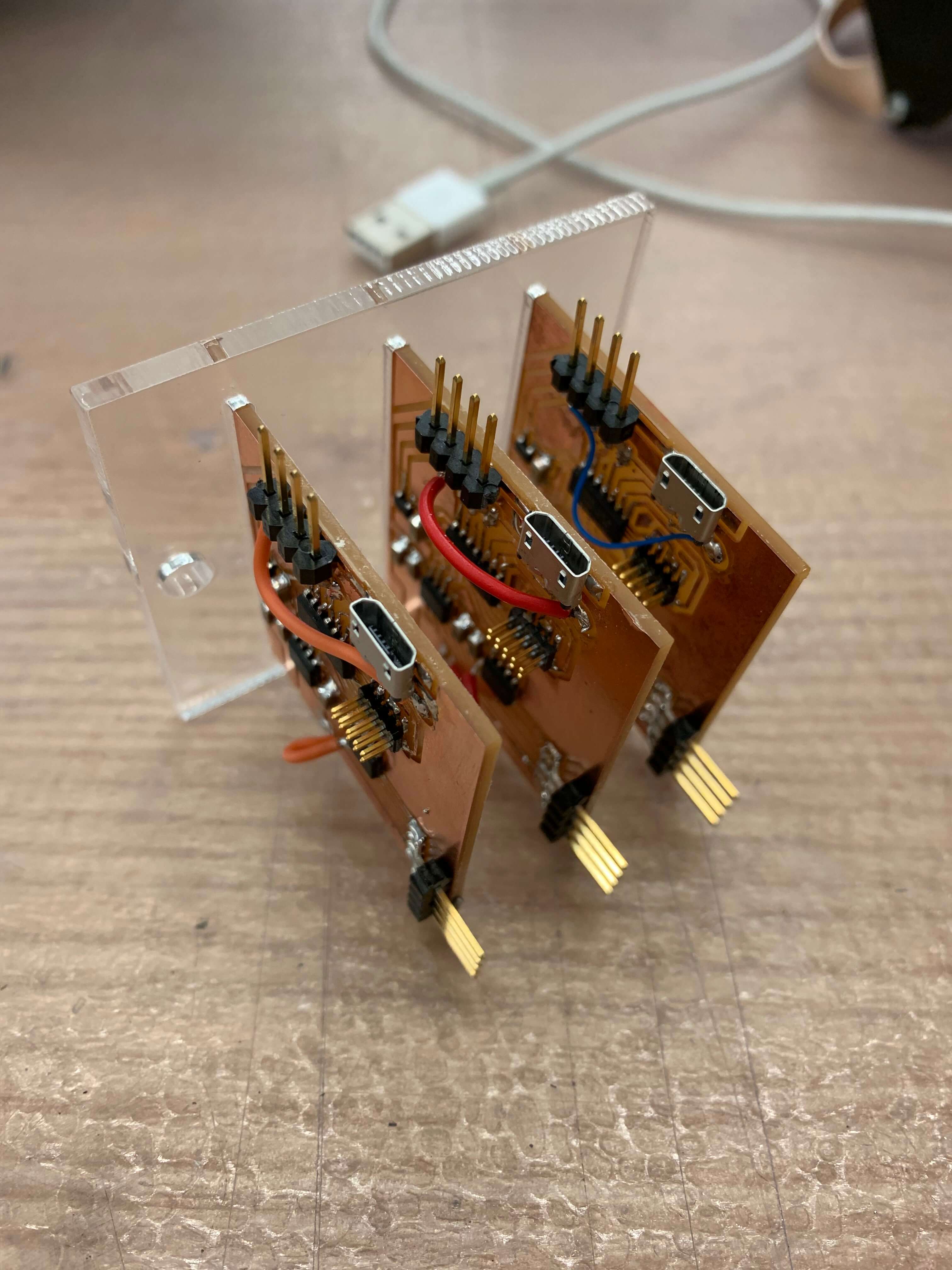
Since I didn't want to have three sets of alligator clips coming from the power supply to the driver boards, I decided to solder bus bars to the board array. I first tried using pieces of Aluminum...
However, the solder joint weren't strong even when using flux and heating up the metals for a long time. I didn't want to damage the boards so I decided to switch over to some copper stripping that I found in my lab and that soldered much better!
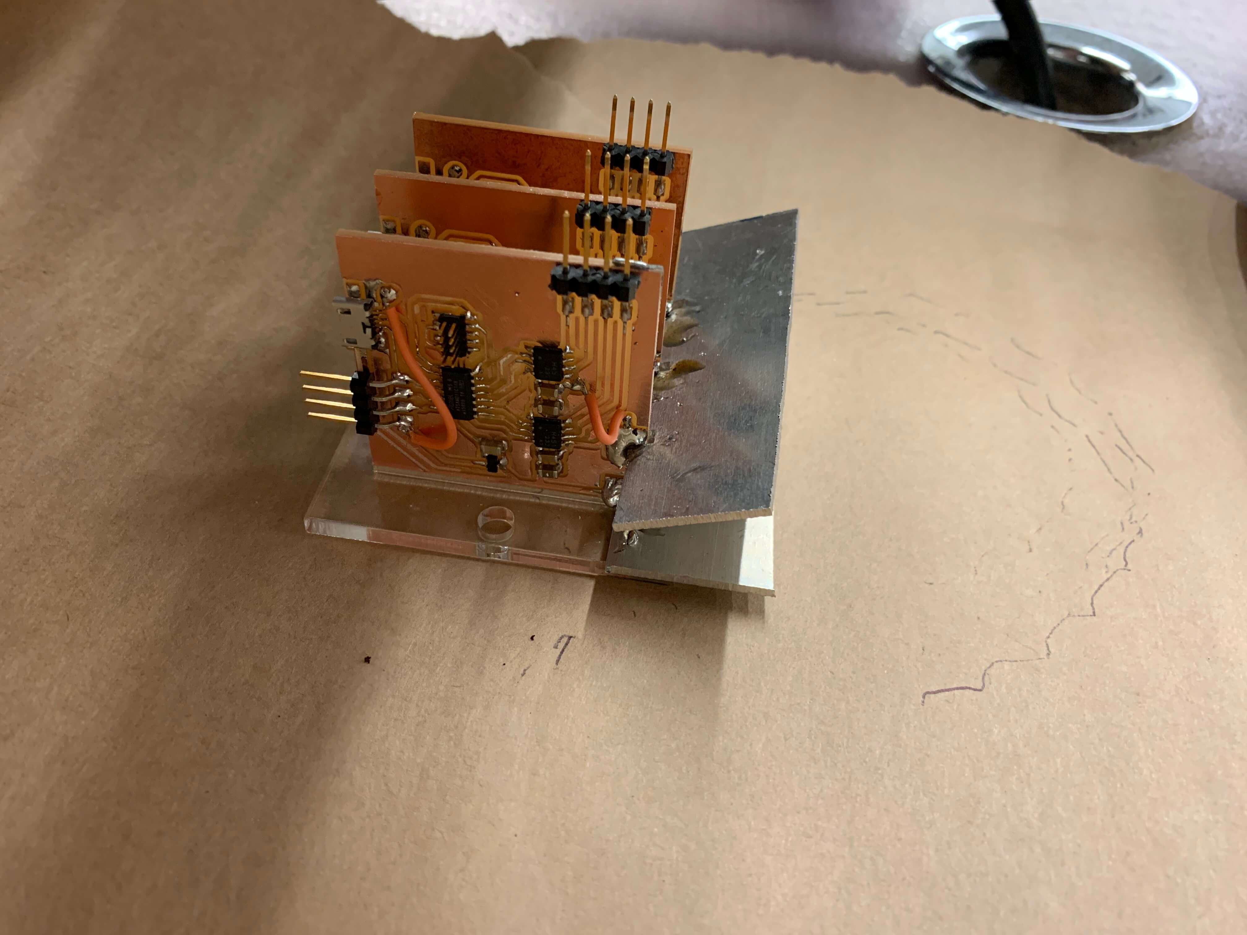
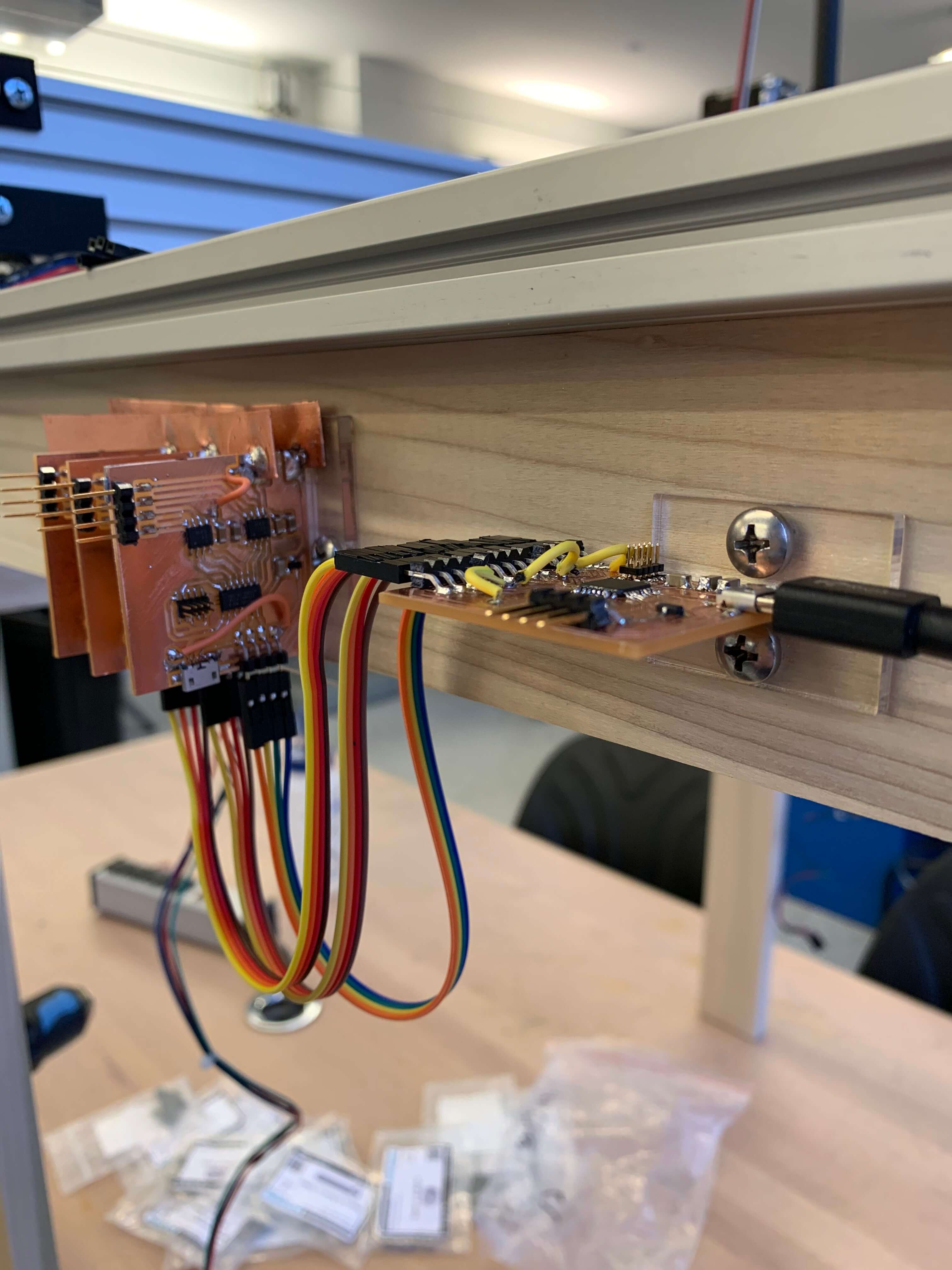
Finally, I made a simlar slotted acrylic piece to hold the main controller, I thought a little about the orientation to interface nicely with the driver boards and the computer through USB. Here's the outline of the main controller holder.
The result is a nice little mounting system which looks like this...
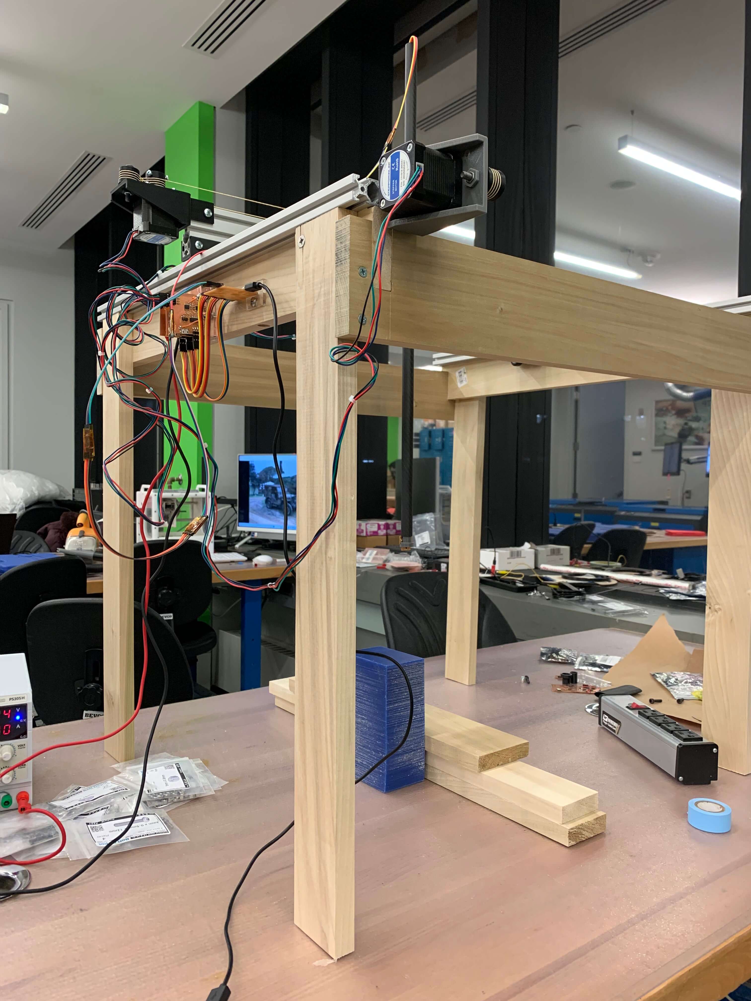
The overall integrated machine, in all its beauty...
Here are the design files for the PCB holders.
Sub-system Validation
A quick (but very blurry) little test that shows whether I am skipping steps or not. I set two different points for the zero and the home and move between the two points.
I ran this a couple of times and had to iterate through driving methods. The biggest difference came when I included a hold statement on the driver boards so that if it doesn't detect a pulse, the board will send out a PWM that holds the current position (I had been previously turning the PWM off when it didn't detect a pulse).
Full System Validation
To validate the full system working together and functioning properly, I placed a Neodynium magnet sideways on a raised block and measured the field around the magnet.
Here's the full work flow sequence showing me inputting the dimensions, the probing sequence, and then the end resulting magnetic field plotted.