Week 12 - Machine Week
This week was a disaster... Not only was I the only one out of 19 students in my section that didn't get the (obvious) memo that this week was a group assignment, I went off and tried to design and build a linear actuator for my final project and the linear actuator turned out to be non-viable for several reasons. I guess I'll just dive in...
My intention was to build a linear actuator similar to the lead screw and rail on the Prusa.
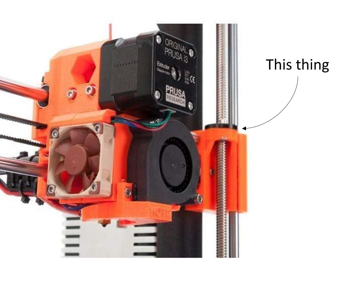
Because the size of my final project is large (in order to fit permanent magnet rotors, transformers and the likes) I needed a very long (and sturdy) lead screw for this mechanism. Unfortunately, lead screws at a length of 2' are hard to find and expensive once you do find them. So I went to Home Depot and bought a threaded rod at 0.5" diameter and with 13 TPI. I also found a nut that mates to the threaded rod. A designed the linear actuator mechanism around this and a 0.5" diameter aluminum tube to be used as the rail. The threaded rod and nut I thought would have some place but still be viable if ddidn't care about too fine of measurements. The following images show CAD models of the parts that constitute a single axis.
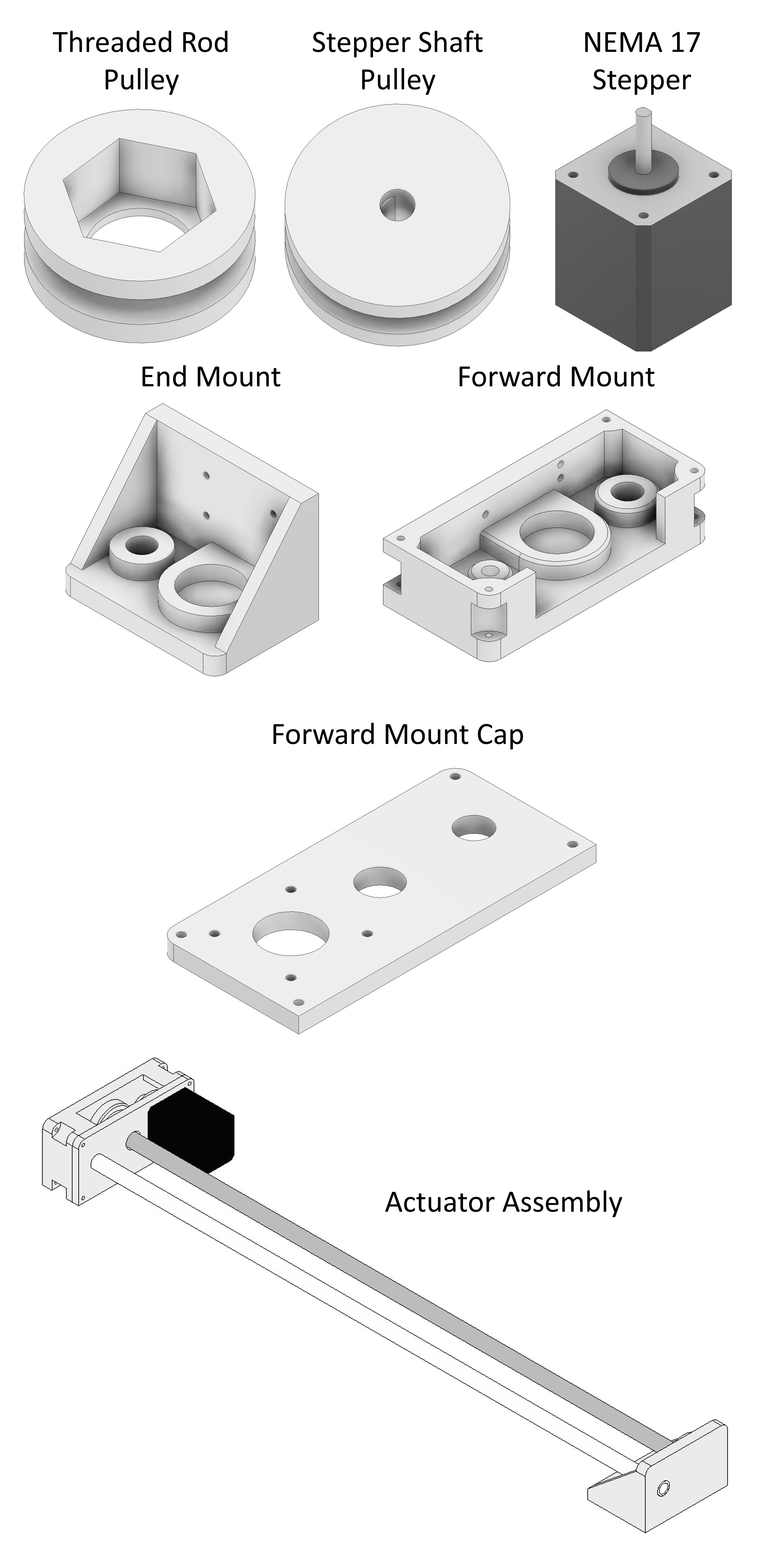
The idea is to have holes for the rails on the forward and end mount for the aluminum rail. This would be a tight fit and be expoxied to fix the geometry, constraining it in all directions. Then the threaded rod, which is held in by a bearing at both mounts, has a pull attached at the stepper-driven end via a nut pressfit inserted and glued into place. Locktite would be used on the nut to keep it from rotating on the threaded rod. Therefore, torque transmitted to the pulley should rotate the threaded rod. I made some bad design choices that led to severe friction here.
Another pully is mounted directly to the shaft of the stepper motor with a flat face insert for press fitting. This also has friction problems and I should've included a set screw to prevent from stripping as the flat face will undoubtedly strip out. I intitiated the 3D print of all of these parts on a Snapmaker available in my lab. Midway through the print, I ran out of filament and had to switch out, resluting in a different color.
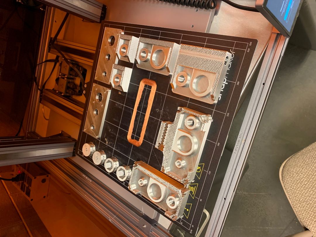
After the print completed, which took over 24 hours, I removed the parts from the printbed and removed the support material.
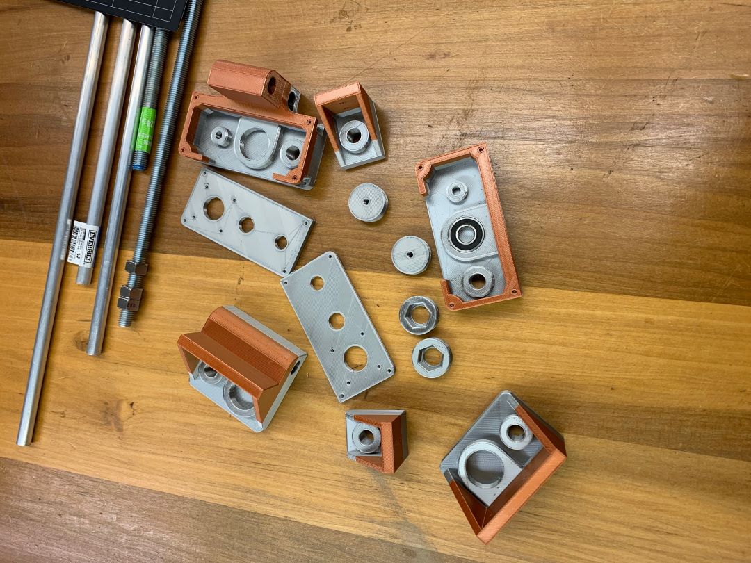
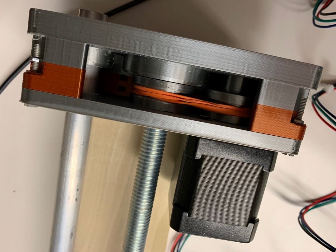
I started testing out fits of the printed parts to the purchased components. Most of the parts fit, be it very tightly. Some of them, such as the stepper shaft pully, needed to be heated with a blow dryer before instertion. Here's a picture of the bearing inserted into its allocated groove.
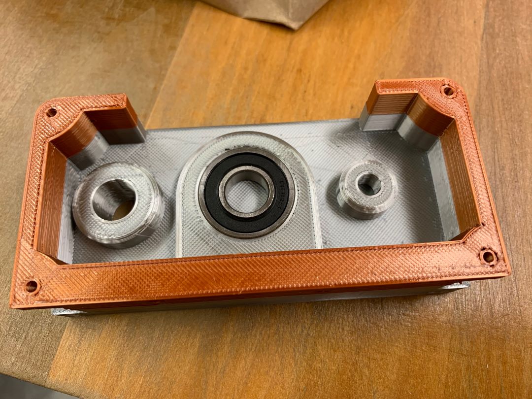
Unfortunately, due to poor design, both components of the bearing rub up with a flat surface at one end, causing more friction. Additionally, it turns out the OD of the the aluminum rail was off the nominal 0.5" dimension (too large). This meant that I needed to file down the ID of all of the rail guides, which were intended to be close-fit inserts. The result is a lot of elbow greease and guides that no longer properly constrain the rail. I could overcome this with glue, however, this would be a permanent solution and I wouldn't be able to get in and modify anything in the future.
Regardless, I proceeded with the design and attempted to assemble the linear actuator...
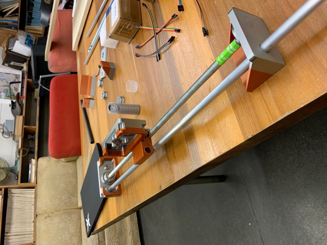
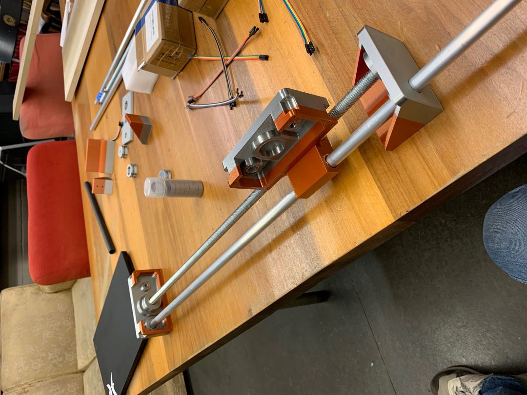
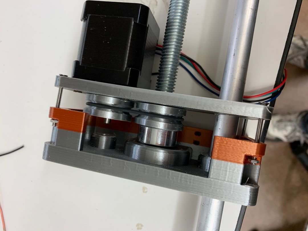
Another problem arose with the torque transmission from the stepper pulley to the threaded rod. I didn't have a clear idea of how to do this, but I had worked under the naive assumption that a really tight rubberband would work as a nice belt (even against Anthony's suggestion, which I obviously should've listened to).
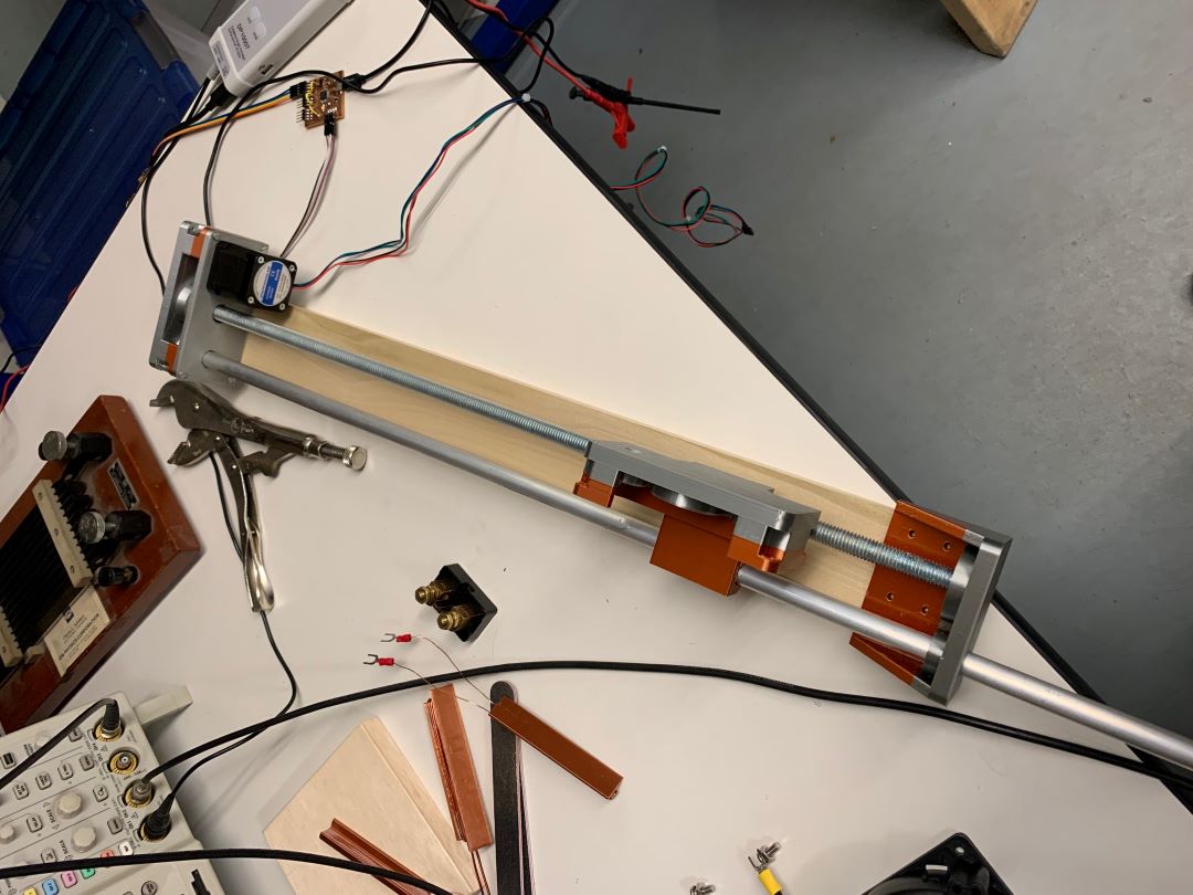
The combination of excesive friction, a moving nut on the threaded pulley (since I didn't want to use loctite until I was sure this would work), give in the rubber band (elasticity is a thing), misalignment, and also probably poor stepper action made this just completely fail. I then used Anthony's suggestion to tighten the nut against a set screw collar to prevent it from rotating without permentantly gluing and replace the rubbberband with a oring. The oring was a tight fit but it just made it. And tighten the nut against the collar worked. I had successful step-by-step transmission from the threaded rod to the stepper motor, but misaligntment issues and the stepper motor control problems (asynchronous rising edge detection), made this unsuccessful.
My final project will cover a new machine mechanism (completing the topic of this week) that will be based off wheels and aluminum extrusions for guiding the wheels. The method will use kevelar string pullys to move the rollers along the rail. This result in much less friction, a modular and light weight system, and there are several references that I can build off in Fab Academy.
Design files for this week can be found here.